Sign In
Upload
Download
Table of Contents
Contents
Add to my manuals
Delete from my manuals
Share
URL of this page:
HTML Link:
Bookmark this page
Add
Manual will be automatically added to "My Manuals"
Print this page
×
Bookmark added
×
Added to my manuals
Manuals
Brands
Thermo Scientific Manuals
Laboratory Equipment
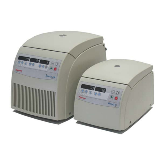
MicroCL 17
Instructions for use manual
Thermo Scientific MicroCL 17 Instructions For Use Manual
Hide thumbs
Also See for MicroCL 17
:
Service manual
(64 pages)
1
2
3
4
Table Of Contents
5
6
7
8
9
10
11
12
13
14
15
16
17
18
19
20
21
22
23
24
25
26
27
28
29
30
31
32
33
34
35
36
37
38
39
40
41
42
43
44
45
46
47
48
49
50
51
52
53
54
55
56
57
58
59
60
61
62
63
64
65
66
67
68
69
70
71
72
73
74
75
76
77
78
79
80
81
82
83
page
of
83
Go
/
83
Contents
Table of Contents
Troubleshooting
Bookmarks
Table of Contents
Table of Contents
For Your Safety
Safety Instructions in this Manual
Proper Use
Improper Use
Centrifuging Hazardous Materials
Handling the Centrifuge
Conformity to Current Standards
Description of the Instrument
Pieces Delivered
Safety Systems
Properties
Before Use
Where to Install the Centrifuge
Transport and Installation the Centrifuge
Centrifuge with Refrigeration Unit
Mains Connection
Removing the Transport Protection
Accessories
Rotors for the IEC MIRCO CL 17
Rotors for the IEC MICRO CL 21
Rotors for the IEC MICRO CL 17R
Rotors for the IEC MICRO CL 21R
Adapter
Handling the Rotor
Rotor Lid with a Spring Lock
Operation Without Rotor Lid
Rotor Lid with Screw Plug
Aerosol-Tight Application
Checking for Aerosol-Tightness
Operation
Switching on the Centrifuge
Opening the Lid
Closing the Lid
Installing the Rotor
Loading the Rotor
Maximum Load
Filling the Centrifuge Tubes
Placing the Tubes in the Rotor
Entering Parameters
Switching from Speed to RCF Display
Selecting Speed
Entering the RCF Value
Concerning the RCF Value
Selecting the Run Time
Run Time Selection
Continuous Operation
Setting the Temperature
Pretemp
Starting the Centrifuge
Changing the Settings During the Run
Stopping the Centrifuge
Preset Run Time
Continuous Operation
Short-Time Centrifugation
Removing the Rotor
Audible Alarm
Turning off the Centrifuge
WEEE Compliance
Maintenance and Care
Maintenance to be Performed by the Customer
Cleaning
Cleaning the Filter Unit
Disinfection
Decontamination
Autoclaving
The Thermo Electron Service Offer
Warranty Conditions
Troubleshooting
Mechanical Emergency Lid Release
Problems You Can Handle Yourself
Contacting Service
Technical Data
Component Parts
The "Easycontrol" User Interface
Performance
Electrical Connections
Appendix
Speed / RCF Diagram
Autoclaving Protocol
Index
Advertisement
Quick Links
Download this manual
IEC
M
CL 17/ 17R 21/21R
ICRO
Instructions for use
Table of
Contents
Previous
Page
Next
Page
1
2
3
4
5
Advertisement
Table of Contents
Need help?
Do you have a question about the MicroCL 17 and is the answer not in the manual?
Ask a question
Questions and answers
Related Manuals for Thermo Scientific MicroCL 17
Laboratory Equipment Thermo Scientific Pico 17 Service Manual
(64 pages)
Laboratory Equipment Thermo Scientific MaxQ Mini 4450 series Operating Manual And Parts List
Benchtop orbital shakers (40 pages)
Laboratory Equipment Thermo Scientific MaxQ Mini 4450 Manual
(32 pages)
Laboratory Equipment Thermo Scientific VARIOMAG MINI 07 Operating Manual
Magnetic stirrer (31 pages)
Laboratory Equipment Thermo Scientific Thermo Scientific Sorvall Legend Micro Series Instruction Manual
(94 pages)
Laboratory Equipment Thermo Scientific Sorvall Legend Micro 17 Instruction Manual
Centrifuge (83 pages)
Laboratory Equipment Thermo Scientific MicroCL 21R Instructions For Use Manual
(83 pages)
Laboratory Equipment Thermo Scientific Mini 11-100 Customer's Manual
Digital c-level . continuous level indicator (67 pages)
Laboratory Equipment Thermo Scientific Medifuge Instructions For Use Manual
(72 pages)
Laboratory Equipment Thermo Scientific EVOS M5000 Quick Reference Instructions
Imaging system (12 pages)
Laboratory Equipment Thermo Scientific ModulyoD Instruction Manual
5l freeze dryer (30 pages)
Laboratory Equipment Thermo Scientific Safe 2020 Operating Instructions Manual
Safety cabinets (71 pages)
Laboratory Equipment Thermo Scientific myECL Imager Manual
(76 pages)
Laboratory Equipment Thermo Scientific MaxQ 7000 User Manual
Benchtop water bath shakers (45 pages)
Laboratory Equipment Thermo Scientific Multifuge X1R Instruction Manual
(58 pages)
Laboratory Equipment Thermo Scientific Multidrop Combi+ User Manual
(122 pages)
This manual is also suitable for:
Microcl 17r
Microcl 21
Microcl 21r
Table of Contents
Print
Rename the bookmark
Delete bookmark?
Delete from my manuals?
Login
Sign In
OR
Sign in with Facebook
Sign in with Google
Upload manual
Upload from disk
Upload from URL


Need help?
Do you have a question about the MicroCL 17 and is the answer not in the manual?
Questions and answers