Advertisement
ECx-400 UUKL Extension Modules
Product Description
This document describes the hardware installation procedures for the ECx-400 Series I/O Extension Modules.
The Distech Controls ECL-600 and ECB-600 Series controllers product line is designed to control and monitor various HVAC equipment such as roof top
units, large air handling units as well as central plant applications such as chillers and boilers. These controllers are compatible with the I/O Extension
Module product line, which includes the following modules: ECx-400, ECx-410, ECx-420, and ECx-400 UUKL.
This document describes the hardware installation procedures for the ECx-400 UUKL Extension Modules only.
The ECx-400 UUKL I/O Extension module is the only model to be used in the Distech Controls UUKL smoke control system. For detailed
requirements, specifications, and procedures for installing and operating UL 864 Listed equipment, you must refer to the Distech Controls
UUKL Smoke Control System Design Guide (UUKL Design Guide_UG_10_EN). Failure to meet the requirements or follow the procedures in
the Distech Controls UUKL Smoke Control System Design Guide can void the UL 864 Listing for smoke control equipment.
These I/O Extension Modules are all built on a similar platform, but have different numbers of inputs and outputs. Moreover, each individual
model has different amounts of digital and/or universal outputs. For more information on the specific layout and functionality of each I/O
Extension Module, please refer to the ECB-600 datasheets.
General Installation Requirements
For proper installation and subsequent operation of the device, pay special attention to the following recommendations:
£
It is recommended that the controller(s) be kept at room temperature for at least 24 hours before installation to allow any condensation that may
have accumulated due to low temperature during shipping/storage to evaporate.
£
Upon unpacking, inspect the contents of the carton for shipping damages. Do not install a damaged device.
£
The device is designed to operate under environmental conditions that are specified in its datasheet.
£
Ensure proper ventilation of the device and avoid areas where corroding, deteriorating or explosive vapors, fumes or gases may be present.
£
Allow for proper clearance around the device's enclosure and wiring terminals to provide easy access for hardware configuration and maintenance.
£
When installing in an enclosure, select one that provides sufficient surface area to dissipate any heat generated by the device and by any other de-
vices installed in the enclosure. A metal enclosure is preferred. If necessary, provide active cooling for the enclosure.
£
Orient the controller with the ventilation slots and power supply/output terminal block connectors towards the top to permit proper heat dissipation.
£
The device's plastic enclosure has a back plate that is separable from the front plate allowing the back plates (with the connectors) to be shipped di-
rectly to the installation site while all the engineering is done in the office.
£
The device's datasheet specifies the power consumption (amount of heat generated), the operating temperature range, and other environmental
conditions the device is designed to operate under.
£
Ensure that all equipment is installed according to local, regional, and national regulations.
£
Do not drop the device or subject it to physical shock.
£
If the device is used and/or installed in a manner not specified by Distech Controls, the functionality and the protection provided by the device may
be impaired.
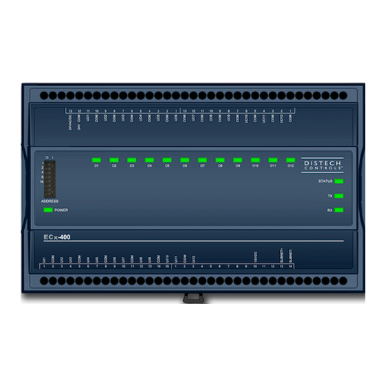
Figure 1:
ECx-400 UUKL model
I n s t a l l a t i o n G u i d e
Advertisement
Table of Contents

Related Manuals for Distech Controls ECx-400 Series


Summary of Contents for Distech Controls ECx-400 Series
- Page 1 £ Do not drop the device or subject it to physical shock. £ If the device is used and/or installed in a manner not specified by Distech Controls, the functionality and the protection provided by the device may be impaired.
-
Page 2: General Wiring Recommendations
Any type of modification to any Distech Controls product will void the product’s warranty Take special care to keep the front and back plate aligned when separating and joining them. Take reasonable precautions to prevent electrostatic discharge to the device when installing, servicing or during operation. Discharge accumulated static electricity by touching one’s hand to a well-grounded object before working with the device. - Page 3 I/O Extension Module Dimensions & Components Figure 2: Rear view of large enclosure Figure 3: Side view of large enclosure 3 / 16...
-
Page 4: Mounting Instructions
Mounting Instructions The controller can be mounted on a DIN rail to speed up the installation procedure. They are also equipped with two mounting holes 0.25” x 0.165” (6.35mm x 4.191mm). The I/O Extension module can be mounted in a panel or on a wall by using appropriate screw types (use sheet metal, thread forming, or self-tapping screws accordingly). -
Page 5: Power Wiring
The Network Guide provides extensive information and requirements for powering a controller. It can be downloaded from our website. For the UUKL ex- tension module, refer to the Distech Controls UUKL Smoke Control System Design Guide. It is recommended to wire only one controller per 24VAC transformer. -
Page 6: Input Wiring
Input Wiring Before connecting a sensor to the controller, refer to the installation guide of the equipment manufacturer. £ For a wire length less than 75’ (23m), either a shielded or unshielded 18AWG wire may be used. £ For a wire up to 200’ (61m) long, a shielded 18AWG wire is recommended. £... -
Page 7: Output Wiring
Sensor Input Type Input Des- Input Connection Diagram ignation £ Slow Pulse – Internal supply: 2-wire pulse meter, maximum input fre- Controller 5VDC quency of 1Hz (500ms minimum ON/OFF) Pulse Input Equivalent £ Connect the pulse input according to the figure for a pulse meter that 10KΩ... -
Page 8: Communications Wiring
Control System Design Guide. For optimal performance, use Distech Controls 24 AWG (0.65 mm) stranded, twisted pair shielded cable or refer to the Network Guide for cable specifi- cation. For the UUKL extension module, refer to the Distech Controls UUKL Smoke Control System Design Guide. The subnetwork communication wire is polarity sensitive and the only acceptable topology is to daisy-chain the cable from one I/O Extension Module to the next. - Page 9 The total maximum length of all Subnetwork buses, including both the length of the Allure Series Communicating Sensor Subnetwork bus and the ECx-400 Series Subnetwork bus is 300 m (1 000 ft). The maximum length of the Allure Series Communicating Sensor Subnetwork bus is 200 m (650 ft).
-
Page 10: Device Addressing
Setting the EOL Terminations on the ECx-400 Series Subnetwork Bus when Allure EC-Smart-Vue Sensors are used ECx-400 Series devices and Allure EC-Smart-Vue sensors are factory-set with the EOL set to OFF by default. If inserting multiple wires in the terminals, ensure to properly twist wires together prior to inserting them into the terminal connectors. - Page 11 Strain relief and Terminal Block Cover In certain jurisdictions, terminal block covers are required to meet local safety regulations. Strain reliefs and terminal block covers are available for con- trollers housed in large enclosures and are used to relieve tension on the wiring and conceal the controllers’ wire terminals. Strain reliefs and terminal block covers are optional and are sold as peripherals.
-
Page 12: Maintenance
Directive applies to standalone products, for example, products that can function entirely on their own and are not a part of another system or piece of equipment. For this reason, Distech Controls are exempt from the WEEE Directive. Nevertheless, Distech Controls products are marked with the WEEE symbol indicating devices are not to be thrown away in municipal waste. - Page 13 Typical Air Handling Unit Application Wiring Diagram Supply Return Heat Cool Damper Humidifier Starter Starter Fuse: 4A Max. 0-10 0-10 0-10 0-10 Transformer Fast Acting 24VAC Electrical System Ground ECx-400 Data Bus Shields: Twist together and Isolate with electrical tape * 249 ohm resistor built-in for inputs configured as 4-20mA Figure 13: Typical Power and Network Connections...
-
Page 14: Troubleshooting Guide
Network length Check that the total wire length does not exceed the specifications in the Network Guide or for the UUKL extension module refer to the Distech Controls UUKL Smoke Control System Design Guide . Wire type Check that the wire type agrees with the specification of the Network Guide or for the UUKL extension module refer to the Distech Controls UUKL Smoke Control System Design Guide. - Page 15 15 / 16...
- Page 16 ©, Distech Controls Inc 2011-2019. All rights reserved. Images are simulated. While all efforts have been made to verify the accuracy of information in this manual, Distech Controls is not responsible for damages or claims arising from the use of this manual.
Need help?
Do you have a question about the ECx-400 Series and is the answer not in the manual?
Questions and answers