Table of Contents
Advertisement
Quick Links
Advertisement
Table of Contents

Related Manuals for Sole Fitness SB800 Air Bike


Summary of Contents for Sole Fitness SB800 Air Bike
-
Page 2: Product Registration
Product Registration Important Safety Instructions Important Operation Instructions Assembly Instructions Operation of Your New Manufacturer’s Limited Warranty... - Page 3 CONGRATULATIONS ON YOUR NEW ROWER AND WELCOME TO THE SOLE CONGRATULATIONS ON YOUR NEW AIR BIKE AND WELCOME TO THE SOLE FAMILY! FAMILY! Thank you for your purchase of this quality Sole Air Bike from Dyaco Canada Inc. Your has been manufactured by one of the leading fitness manufacturers in the world and is backed by one of the most comprehensive warranties available.
-
Page 4: Important Safety Instructions
IMPORTANT SAFETY INSTRUCTIONS Thank you for purchasing our product. Even though we go to great efforts to ensure the quality of each product we produce, occasional errors and /or omissions do occur. In any event should you find this product to have either a defective or a missing part please contact us for a replacement. - Page 5 WARNING: BEFORE BEGINNING ANY EXERCISE PROGRAM CONSULT YOUR PHYSICIAN. THIS IS ESPECIALLY IMPORTANT FOR INDIVIDUALS OVER THE AGE OF 35 OR PERSONS WITH PRE-EXISTING HEALTH PROBLEMS. READ ALL INSTRUCTIONS BEFORE USING ANY FITNESS EQUIPMENT. WE ASSUME NO RESPONSIBILITY FOR PEROSNAL INJURY OR PROPERTY DAMAGE SUSTAINED BY OR THROUGH THE USE OF THIS PRODUCT.
-
Page 6: Before You Begin
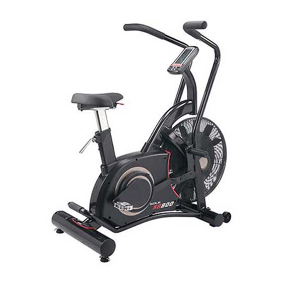
BEFORE YOU BEGIN Thank you for choosing the Sole SB800 Air Bike. We take great pride in producing this quality product and hope it will provide many hours of quality exercise to make you feel better, look better, and enjoy life to its fullest. It's a proven fact that a regular exercise program can improve your physical and mental health. - Page 7 Console tube Main frame Front stabilizer Rear stabilizer Swing handle bar (L-R) (G-1)Foot Support (G-2)End Cap Console (H1) Pedal(left) Metal fixing plate (H2) Pedal(right) Tool (J1)Screw (J2)Screw (J3)Spacer (J4)NUT M8*60 M8*30 Ring Wrench Screw driver (J5)Screw (J6)Screw Customized Wrench 4m/m 5m/m 6m/m M6*16...
- Page 8 HOW TO ASSEMBLE FRONT STABILIZER Step 1. Loosen the two screws (J6) from the paper strap. The paper strap is used for package protect be used again during/after assembly. STEP 2. the front stabilizer (B) onto main frame (A) and tight (J6).
- Page 9 HOW TO ASSEMBLE LEFT & RIGHT SWING HANDLE BARS & FOOT SUPPORT Equip right swing handle bar (D2) and then install one spacer ring (J8) onto to main frame (A). Next, assemble the foot support (G). Fasten the Foot support with the Customized Wrench, and then put on the End cap (G1).
- Page 10 HOW TO ASSEMBLE THE PEDALS Step 1. Loosen the screw (J7) from the crank (A8). Step 2. the right pedal (H2) onto the crank (A8) and fasten with Step 3. Fasten the screw(J7) onto the crank. USE TOOL 5m/m HOW TO ASSEMBLE THE CONSOLE TUBE Connect the cables (E1) and (A30) together, then using screw (J1) console tube (E) main frame.
-
Page 11: How To Move The Machine
HOW TO ASSEMBLE THE CONSOLE Remove the pre-installed screws from console housing (F-1). Connect the cables (E1) and the wire from console (F-1) together install console onto console tube (F2). USE TOOL Screw driver HOW TO MOVE THE MACHINE The front stabilizer has built-in transport wheels. Stand at the rear and lift the machine up until the weight is transferred to the transport wheels. - Page 12 HOW TO ADJUST S POST AND SADDLE STEP 1 Step 1. Pull up the (A32) Step 2. Pull up the adjustment bar(A55)to adjust t saddle position. release the STEP 2 Remove the battery cover and install the new batter . Battery specifications: AA * 4pcs.
-
Page 13: Display Functions
CUSTOM 20/10 10/20 INTERVAL TOTAL TIME CYCLE WATTS TIME TOTAL REMAININGELAPSED ML/Hr SPEED DISTANCE KM/Hr KILOMETERSMILES CALORIES USE UP & DOWN KEYS TO ADJUST PRESS ENTER TO ACCEPT TOTAL TARGET HEART RATE ACHIEVED HEART RATE NO HR SIGNAL sec. sec. Interval Custom Interval 20 - 10 Interval 10 - 20... - Page 14 BOTTON FUNCTION ITEM DESCRIPTION -To p use workout during exercise or resume workout in Stop mode. START -Hold on pressing it for 2s to switch among KM and ML. -To stop workout during exercise. STOP -Any time hold on this key for 2 seconds to reboot the console as TOTAL RESET. -To adjust Distance, Calories, Time, Age value down.
- Page 15 2. The icons of INTERVAL, READY, WORK, REST, TIME, TAG CALORIE TAG DISTANCE , IME, DISTANCE, CALORIES, WATTS, SPEED, RPM, HEART RATE will flash by sequence in every 1s (Figure 4~Figure 17). If no input of key operation, RPM signal or pulse input for 5 minutes, computer will go to Sleeping mode. Figure 7 Figure 4 Figure 5...
- Page 16 Figure 16 Figure 17 3. Select Manual, INTERVAL 20-10, INTERVAL 10-20, INTERVAL CUSTOM,TARGET TIME, TARGET DISTANCE, TARGET CALORIES and TARGET HR program: 3.1 Manual mode: In Standby mode, if there is RPM input, console will QUICK START to start workout immediately, the buzzer sound 1 second.
- Page 17 Figure 21 Figure 22 Figure 23 PAUSE START QUICK START STOP 3.2 INTERVAL 20-10 mode: In Standby mode, press 20/10 key to enter it, the icon will light up along with a long sound for one second. CYCLE TIME will count down for 3s and buzzer sound once per second,then system start. “READY”...
- Page 18 Figure 24 Figure 25 Figure 26 Figure 27 Figure 28 PAUSE START Interval 20 - 10 STOP...
- Page 19 3.3 INTERVAL 10-20 mode: In Standby mode, press 0/20 key to enter it, the icon will light up along with a long sound for one second. CYCLE TIME will count down for 3s and buzzer sound once per second,then system start. “READY”...
- Page 20 3.4 INTERVAL CUSTOM mode: In Standby mode, press INTERVAL CUSTOM key to enter it. The 00/XX is flashing, “USE UP& DOWN KEYS TO ADJUST and PRESS ENTER TO ACCEPT” will swicth to display, buzzer sound one second. press UP/DOWN to adjust 00/XX value (setting range 1~99) and press ENTER to confirm. (Figure 33) Buzzer sound for one second.
- Page 21 Figure 37 Figure 38 Figure 39 Figure 40 CYCLE WORK TIME Interval Custom ENTER ENTER DOWN DOWN PAUSE START REST TIME ENTER STOP DOWN 3.5 TARGET TIME mode: In Standby mode, press TAG TIME key and enter it.TAG TIME will light up, “USE UP&...
- Page 22 Figure 41 Figure 42 Figure 43 PAUSE START Target Time Target Time ENTER STOP DOWN 3.6 TARGET DISTANCE mode: In Standby mode, press TAG DISTANCE key to enter it. TAG DISTANCE will light up, “USE UP& DOWN KEYS TO ADJUST and PRESS ENTER TO ACCEPT” will swicth to display, buzzer sound DISTANCE value is flashing, press UP and DOWN to adjust (Figure 44).
- Page 23 Figure 44 Figure 45 Figure 46 PAUSE START Target Distance Target Distance ENTER STOP DOWN 3.7 TARGET CALORIES mode: In Standby mode, press TAG CALORIES key to enter it. TAG CALORIES will light up, “USE UP& DOWN KEYS TO ADJUST and PRESS ENTER TO ACCEPT” will swicth to display, buzzer sound 1s.
- Page 24 Figure 47 Figure 48 Figure 49 PAUSE START Target Calories STOP Target Calories ENTER DOWN 3.8 TARGET HR mode: In Standby mode, press TAG HEART RATE key to enter it. TAG HEART RATE will light up, “USE UP& DOWN KEYS TO ADJUST PRESS ENTER TO ACCEPT ”will swicth to display, buzzer sound 1s.
- Page 25 Figure 50 Figure 51 Figure 52 Figure 53 Figure 51 PAUSE START STOP Target Heart-Rate ENTER DOWN...
-
Page 26: Using Heart Rate Transmitter
USING HEART RATE TRANSMITTER Note Caution! - Page 28 J3 J4 J2*2 J5*6 A34*2 B3*2 B2*2 B1*2 B4*2 J6*8 J7*2 B5*2 B6*4 A36*2 C2*2 C1*2 A35*2 C3*2...
- Page 29 DESCRIPTION Q”TY DESCRIPTION Q”TY ADJUSTMENT BAR MAIN FRAME BELT WHEEL 360mm QUICK-RELEASED AXIS SCREW M6*15 BELT 690 J6 MAGNETIC ( 15*7mm) THREADED ROD SCREW M8*35 SPRING BALL 10mm STEEL FAN PIECE PLASTIC STRIP SPACER BLOCK SHAPED CRANK-L SPRING SHAPED CRANK-R BUSH( 8* 12*7mm) A10 WASHER M5* 13*1T NUT M6...
- Page 30 DESCRIPTION Q”TY DESCRIPTION Q”TY CONSOLE SPACER RING NUT M8 SCREW FOOT SUPPORT SCREW M6*12mm 100mm PEDAL-L SCREW M10*20mm SCREW M6*8mm PEDAL-R METAL FIXING PLATE SCREW M8*60mm SCREW M8*30mm...
-
Page 31: Training Guidelines
Training Guidelines Exercise Exercise is one of the most important factors in the overall health of an individual. Listed among its benefits are: Increased capacity for physical work (strength endurance) Increased cardiovascular (heart and arteries/veins) and respiratory efficiency Decreased risk of coronary heart disease Changes in body metabolism, e.g. - Page 32 Specificity Different forms of exercise produce different results. The type of exercise that is carried out is specific both to the muscle groups being used and to the energy source involved. There is little transfer of the effects of exercise, i.e. from strength training to cardiovascular fitness.
-
Page 33: Body Building
Two final comments:(1) don’t be concerned with day to day variations in your pulse rate, being under pressure or not enough sleep can affect it;(2) your pulse rate is a guide, don’t become a slave to it. Endurance Circuit Training Cardiovascular endurance, muscle, strength, flexibility and coordination are all necessary for maximum fitness. - Page 34 STRETCHING Stretching should be included in both your warm up and cool down, and should be performed after 3-5 minutes of low intensity aerobic activity or callisthenic type exercise. Movements should be performed slowly and smoothly, with no bouncing or jerking. Move into the stretch until slight tension, not pain, is felt in the muscle and hold for 20-30 seconds.
- Page 35 INNER THIGH STRETCH TOE TOUCHES Sit with the soles of your feet together with your Slowly bend forward from your waist, letting knees pointing outward. Pull your feet as close your back and shoulders relax as you stretch Into your groin as possible. Gently push your toward your toes.
Need help?
Do you have a question about the SB800 Air Bike and is the answer not in the manual?
Questions and answers