Sole Fitness SB700 Service Manual
Hide thumbs
Also See for SB700:
- Owner's manual (20 pages) ,
- Owner's manual (16 pages) ,
- Owner's manual (26 pages)

Related Manuals for Sole Fitness SB700


Summary of Contents for Sole Fitness SB700
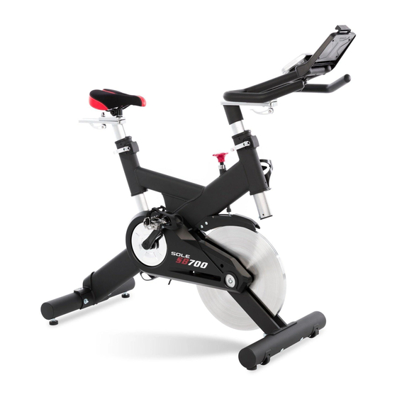
- Page 1 SB700 Service Manual Unit Outline Seat Cushion Tube Insert Brake Tension Knob Stabilizer End Cap Quick Release Pulley Cover Flywheel Fender Outer Chain Cover Stabilizer End Cap Rear Stabilizer Cover Bottom End cap Pedal Eye Tube End Cap...
- Page 2 Skeleton Seat Post Sliding Seat Mount Main Frame Handlebar Post Sliding Handlebar Mount Handlebar Rear Stabilizer Drive Pulley Inner Chain Cover Flywheel Leather Brake Pad Front Stabilizer Crank Arm Idler Axle HUB PULLEY...
-
Page 3: Table Of Contents
Contents I. Replacing Parts Outer Chain Cover 2. Flywheel Fender, Brake Tension Knob and Leather Brake Pad 3. Flywheel and Flywheel Axle 4. Clank Arms and Pedal Set and Drive Pulley, Crank Axle and Pulley Cover 5. Idler Axle and Idler Adjustment Carriage Bolt 6. -
Page 4: Outer Chain Cover
Model SB700 Work Replacing Parts 1. Outer Chain Cover Part Steps: 1. Use Combinational M5 Allen Wrench & Phillips Head Screwdriver (86) to unscrew two 5×16m/m Tapping Screws (29) and three 3.5×12m/m Sheet Metal Screws to take apart Outer Chain Cover (60). - Page 5 Model SB700 Work Replacing Parts Part Flywheel Fender, Brake Tension Knob and Leather Pad Brake Steps: 1. Use Combinational M5 Allen Wrench & Phillips Head Screwdriver (86) to unscrew four M6×15mm Phillips Head Screws and take apart Flywheel Fender (62).
-
Page 6: Flywheel And Flywheel Axle
Model SB700 Work Replacing Parts Part Flywheel and Flywheel Axle Steps: 1. Follow procedure 2 to remove Flywheel Fender (62), Brake Tension Knob (16) and Leather Pad Brake (10). 2. Use 11m/m open wrench to loosen (turn clockwise) 1/4" × 3"L Hex Head Bolt, which is on Idler Axle (74), and take apart the Belt (40). - Page 7 Model SB700 Work Replacing Parts Part Flywheel and Flywheel Axle Steps: 4. Use Wrench (86) to unscrew six M6×10L Phillips Head Screws (39) and take apart Flywheel (31) and together with Axle (33). 5. Us e the tool as shown in the picture to pull out both left and right Bearing Housing (32) 6.
-
Page 8: Clank Arms And Pedal Set And Drive Pulley, Crank Axle And Pulley
Model SB700 Work Replacing Parts Part Clank Arms and Pedal Set and Drive Pulley, Crank Axle and Pulley Cover Steps: 1. Follow procedures 1 and 3 to remove Outer Chain Cover (60) and Belt (40), respectively. 2. Use 14/15m/m Wrench (85) to take apart left Pedals (25). - Page 9 Model SB700 Work Replacing Parts Part Clank Arms and Pedal Set and Drive Pulley, Crank Axle and Pulley Cover Steps: 5. Use C-ring pliers to release anotherφ20_C Ring (68). 6. Remove Crank Arm Dust Cap (44) which is on right Crank Arm (43) and use 14 m/m plug wrench to release M10×P1.25×7T Nut...
-
Page 10: Idler Axle And Idler Adjustment Carriage Bolt
Model SB700 Work Replacing Parts Idler Axle and Idler Adjustment Carriage Bolt Part Steps: 1. Follow procedures 1 and 3 to remove Outer Chain Cover (60) and Belt (40), respectively. 2. Use M6 hex wrench to take apart Idler Axle (74). -
Page 11: Seat Post And Sliding Seat Mount
Model SB700 Work Replacing Parts Seat Post and Sliding Seat Mount Part Steps: 1. Remove End Cap, Eye Tube (56). 2. Use M4 hex wrench to release M5 × 10m/m Socket Head Cap Screw (89) which is on Seat Post (5) and pull out Seat Post (5). - Page 12 Model SB700 Work Replacing Parts Handlebar, Sliding Handlebar Mount and Handlebar Part post Steps: 1. Like procedure 6, separate Handlebar (6) and Sliding Handlebar Mount (8) from Handlebar Post (4). 2. Use M5 hex wrench to unscrew 5/16" × 5/8"_Button Head Socket Bolt (88) and separate Handlebar (6) from Sliding Handlebar Mount (8).
- Page 13 Model SB700 Work Q&A 1. Slippage and falling off of Belt Problem Solution: 1. If Belt (40) slips, follow procedure 3 to move Idler Axle (74) downward by turning 1/4" × 3"L Hex Head Bolt (69) counterclockwise and tighten the Belt (40) until belt tension reads 700~750 Newton.
-
Page 14: Noises
Model SB700 Work Q&A 2. Noises Problem Solution: 1. Most noise is caused by rubbing between Flywheel (31) and Leather Brake Pad (10) which is normal. -
Page 15: Sliding Seat Mount Or Handlebar Loose
Model SB700 Work Q&A Sliding Seat Mount or Handlebar Loose Problem Solution: 1. If Sliding Seat Mount (7) or Handlebar loose during workout, tighten 8×40m/m_Quick Release lever (19). - Page 16 Model SB700 Work Q&A Display Blank or No Speed Displayed Problem Solution: 1. Make sure there is power for the unit. 2. Make sure Speed Sensor and magnet are well installed. 3. Verify input/output of transmitter signal. 4. If everything is normal, change the transmitter position.
-
Page 17: Others
Model SB700 Work Q&A Other Problem Solution: Most of the problems are explained in above sections. Due to various factors of the root cause, more details of how to solve the problems will be carried out based on the product situation in the field.
Need help?
Do you have a question about the SB700 and is the answer not in the manual?
Questions and answers
How to install flywheel brake on Sole SB700?