Dorner 2100 Series Installation, Maintenance & Parts Manual
Center drive conveyors
Hide thumbs
Also See for 2100 Series:
- Installation, maintenance & parts manual (30 pages) ,
- Installation and maintenance manual (28 pages) ,
- Installation & maintenance (16 pages)
Table of Contents
Advertisement
Quick Links
2100 Series Center Drive Conveyors
. . . . . . . . . . . . . . . . . . . . . . . . . . . . . . . . . . . .
. . . . . . . . . . . . . . . . . . . . . . . . . . . . . .
. . . . . . . . . . . . . . . . . . . . . . . . . . . . . . . . . . .
Installation
. . . . . . . . . . . . . . . . . . . . . . . . . . . . . . . . . . . . .
. . . . . . . . . . . . . . . . . . . . . . . . . . . . . . . .
. . . . . . . . . . . . . . . . . . . . . . . . . . . . . .
Preventative Maintenance & Adjustment
. . . . . . . . . . . . . . . . . . . . . . . . . . . . . . . .
. . . . . . . . . . . . . . . . . . . . . . . . . . . . . .
. . . . . . . . . . . . . . . . . . . . . . . . . . . . . . .
. . . . . . . . . . . . . . . . . . . . . . . . . . . . . . . . . . . .
. . . . . . . . . . . . . . . . . . . . . . . . . . . . . . . . . . .
End Pulley Bearings
. . . . . . . . . . . . . . . . . . . . . . . . . . . . .
. . . . . . . . . . . . . . . . . . . . . . . . . . . . . . . . . . .
Installation, Maintenance
. . . . . . . . . . . . . . . . . . . . . . . . .
. . . . . . . . . . . . . .
. . . . . . . . . . . . . . . . . . . . . .
. . . . . . . . . . . . . . . .
. . . . . . . . . . . .
. . . . . . . . . . . . . . . . . . . . . . . . . .
. . . . . . . . . . . . . .
. . . . . . . . . . . . . . . . . . . . . . . . .
. . . . . . . . . . . . .
. . . . . . . . . . . .
. . . . . . . . . .
. . . . . . . . . . . . . . . . . . . . . .
. . . . . . . . . . . . . . . . . . . . .
. . . . . . . . . . .
. . . . . . . . . . .
. . . . . . . . . . . . .
. . . . . . . . . . . . . . . . .
& Parts Manual
2
2
3
3
. . . . . . . . . . . . . . . . . . . . . . . . . . . . . .
4
5
5
5
5
5
6
6
7
7
7
. . . . . . . . . . . . . . . . . . . . . . . . . . . . . . . . . . .
7
7
7
7
7
127mm to 610mm Wide Center Drive Module
7
51mm, 76mm, 102mm Wide
7
8
8
8
8
8
8
9
Configuring Conveyor Belt Part Number
11
. . . . . . . . . . . . . . . . . . . . . . . . . . . . . . . . . .
Table of Contents
. . . . . . . . . .
. . . . . . . . . . . . . . . . .
. . . . . . . . . . . . . . . . . . . . . .
. . . . . . . . . . . . . . . . . . . . .
. . . . . . . . . . . . . . . . . . . .
. . . . . . . . . . . . . . . . . . . .
. . . . . . . . . . . . . . . .
. . . . . . . . . . . . . . . . . . . . . . . . . . .
. . . . . . . . . . . . . . . . . . . . . . . . .
. . . . . . . . . . . .
. . . . . . . . . . . . . . . . . . . . . . . . . . .
. . . . . . . . . . . . . . . . . . . . . . . . .
. . . . . . . . . . . .
. . . . . . . . . . . . . . . . . . . . . . . . . . .
. . . . . . . . . . . . . . . .
. . . . . . . .
. . . . . . .
. . . . . . .
. . . . . . . . . . . . . . . . . . . . . . . . .
. . . . . . . . . . . . . . . . . . . . .
. . . . . . . . . . . . . . . . . . . . .
. . . . . . . . . . . . . . . . . . . . . . . .
. . . . . . . . . . . . . . . . . . . . . . . . .
. . . . . . . . . . . . . . . . . . . .
. . . . . . . . . . . . . . . . . . . . . . .
. . . . . . . . . . . . . . . . . . . . . . . . . . .
. . . . . . . .
. . . . . . . . . .
851-179 Rev. E
11
12
14
14
14
15
15
16
16
17
18
18
18
18
18
21
21
23
24
26
. . . . . .
28
28
30
31
32
33
34
35
36
36
37
38
Advertisement
Table of Contents

Related Manuals for Dorner 2100 Series


Summary of Contents for Dorner 2100 Series
-
Page 1: Table Of Contents
Installation, Maintenance & Parts Manual 2100 Series Center Drive Conveyors Table of Contents Warnings – General Safety ...... -
Page 2: Warnings - General Safety
D Inspect packages for shipping damage. Contact carrier regarding damage. D Accessories may be shipped loose. See accessory in- structions for installation. 2100 Series Center Drive Conveyors Installation, Maintenance & Parts Manual 851-179 Rev. E Dorner Mfg. Corp. -
Page 3: Product Description
Conveyor Supports: Maximum Distances: K = 457 mm L = 1829 mm** ** For conveyors longer than 3962 mm, install support at joint. Figure 2 2100 Series Center Drive Conveyors Installation, Maintenance & Parts Manual Dorner Mfg. Corp. 851-179 Rev. E... - Page 4 Figure 3) for set-up. Connector Strips (2x) (Attached to conveyor sec- tion) Mounting bracket with return roller Roller guards (2x) Mounting bracket end block (2x) Figure 3 2100 Series Center Drive Conveyors Installation, Maintenance & Parts Manual 851-179 Rev. E Dorner Mfg. Corp.
-
Page 5: Required Tools
(S) and cover plate screws (T) on both sides of the conveyor. Figure 8 While holding the pinion gear (X), tighten cover plate screws (T) to 2 Nm. Figure 5 2100 Series Center Drive Conveyors Installation, Maintenance & Parts Manual Dorner Mfg. Corp. 851-179 Rev. E... -
Page 6: Mounting Brackets With Return Rollers
11). Tighten the screws (AC) to 9 Nm. Figure 9 Figure 11 Attach to support stand. Tighten screws (AD) to 9 Nm. Make sure belt is free to move. 2100 Series Center Drive Conveyors Installation, Maintenance & Parts Manual 851-179 Rev. E Dorner Mfg. Corp. -
Page 7: Required Tools
Mounting Brackets with Return Rollers With a small flat-blade screwdriver, remove plug (AE of Figure 12) from retainer (AF). No lubrication is required. Replace bearings if worn. 2100 Series Center Drive Conveyors Installation, Maintenance & Parts Manual Dorner Mfg. Corp. 851-179 Rev. E... -
Page 8: Maintaining Conveyor Belt
(AL). LOCK OUT POWER before removing guards or If the conveyor is equipped with guiding and performing maintenance. accessories, remove them from one side. 2100 Series Center Drive Conveyors Installation, Maintenance & Parts Manual 851-179 Rev. E Dorner Mfg. Corp. -
Page 9: Belt Removal For Conveyor With Stands
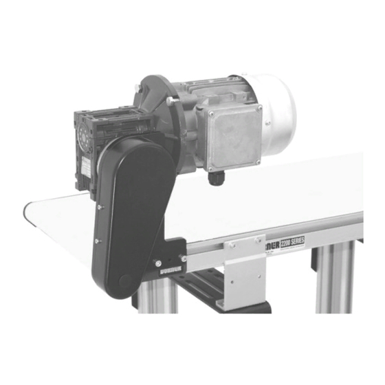
Figure 16 Slide the cam assemblies toward the center of the conveyor and push the end (AV) into the conveyor frame. Figure 17 2100 Series Center Drive Conveyors Installation, Maintenance & Parts Manual Dorner Mfg. Corp. 851-179 Rev. E... - Page 10 Remove three mounting screws (BE of Figure 20) stand to floor or otherwise stabilize the stand. and remove gearmotor package. 2100 Series Center Drive Conveyors Installation, Maintenance & Parts Manual 851-179 Rev. E Dorner Mfg. Corp.
-
Page 11: Center Drive Module Removal
If desired, mark center drive module location on conveyor. Loosen clamp screws (BG of Figure 22) in each cor- ner of the module. Figure 24 2100 Series Center Drive Conveyors Installation, Maintenance & Parts Manual Dorner Mfg. Corp. 851-179 Rev. E... -
Page 12: Installing A New Conveyor Belt
(BQ of Figure 28) point in the direction of belt travel as identified by the label (BP of Figure 26). Figure 28 Place loop of belt into the drive module (Figure 29). 2100 Series Center Drive Conveyors Installation, Maintenance & Parts Manual 851-179 Rev. E Dorner Mfg. Corp. - Page 13 Insert a 5 mm hex key wrench into either end of the pinion gear (BR of Figure 30). Rotate the pinion gear Figure 31 to extend the tensioning end gap (BU) to 30 mm. 2100 Series Center Drive Conveyors Installation, Maintenance & Parts Manual Dorner Mfg. Corp. 851-179 Rev. E...
-
Page 14: Conveyor Belt Tensioning
(BX of Figure 34) from retainer (BY). Figure 33 The conveyor is equipped with an automatic tensioning Figure 34 cylinder. No tensioning adjustment is required. 2100 Series Center Drive Conveyors Installation, Maintenance & Parts Manual 851-179 Rev. E Dorner Mfg. Corp. - Page 15 Remove the gearmotor drive package. Refer to “Belt Removal for Conveyor With Stands and/or Gearmo- tor Mounting Package”, page 9, steps 5 through 7. Figure 38 2100 Series Center Drive Conveyors Installation, Maintenance & Parts Manual Dorner Mfg. Corp. 851-179 Rev. E...
-
Page 16: Bearing Replacement End Pulleys
(CR). Rotate bearing removal tool (CQ) to engage hex tip of extension tool Figure 41 (CU) into screw (CV) of bearing removal tool. 2100 Series Center Drive Conveyors Installation, Maintenance & Parts Manual 851-179 Rev. E Dorner Mfg. Corp. -
Page 17: Bearing Installation
Figure 43 Figure 46 Install bearing insertion tool (CZ of Figure 44), part number 25–10, into arbor press (CY) or similar device. Figure 44 2100 Series Center Drive Conveyors Installation, Maintenance & Parts Manual Dorner Mfg. Corp. 851-179 Rev. E... -
Page 18: Bearing Replacement For Drive Pulley
Reverse removal procedure “A” (see page 14). Drive Pulley Reverse removal procedure “ ” (see page 15). Idler Pulley Figure 48 Reverse removal procedure “ ” (see page 15). 2100 Series Center Drive Conveyors Installation, Maintenance & Parts Manual 851-179 Rev. E Dorner Mfg. Corp. - Page 19 Notes 2100 Series Center Drive Conveyors Installation, Maintenance & Parts Manual Dorner Mfg. Corp. 851-179 Rev. E...
-
Page 20: Service Parts
Service Parts NOTE: For replacement parts other than those shown on this page, contact an authorized Dorner Service Center or the factory. 51mm Wide Conveyor Assembly 2100 Series Center Drive Conveyors Installation, Maintenance & Parts Manual 851-179 Rev. E Dorner Mfg. Corp. - Page 21 Bottom Wiper 6706mm 240402–11508 240402–14400 903–108 Flat Head Screw #10–32 x .50” 7010mm 240402–12708 240402–14400 930512M Flat Head Screw M5 x 12mm 7315mm 240402–13908 240402–14400 2100 Series Center Drive Conveyors Installation, Maintenance & Parts Manual Dorner Mfg. Corp. 851-179 Rev. E...
-
Page 22: 76Mm To 152Mm Wide Conveyor Assembly
Flex–Link Bar 102mm 200028 Tail Plate, SAE, LH 207605 Flex–Link Bar 127mm 200028M Tail Plate, Metric, LH 207606 Flex–Link Bar 152mm 200695P Knurl Pin 2100 Series Center Drive Conveyors Installation, Maintenance & Parts Manual 851-179 Rev. E Dorner Mfg. Corp. - Page 23 3048mm 2404WW–11508 7010mm 2405WW–12708 2405WW–14400 3353mm 2404WW–12708 7315mm 2405WW–13908 2405WW–14400 3658mm 2404WW–13908 3962mm 2404WW–06708 2404WW–07908 WW = Conveyor Width reference: 03, 04, 05, 06 2100 Series Center Drive Conveyors Installation, Maintenance & Parts Manual Dorner Mfg. Corp. 851-179 Rev. E...
-
Page 24: 203Mm To 605Mm Wide Conveyor Assembly
Gear Pinion 254mm 203mm 303108 303208 203012M Gear Pinion 305mm 254mm 303110 303210 902–112 Socket Head Cap Screw #10–32 x .75” 305mm 303112 303212 2100 Series Center Drive Conveyors Installation, Maintenance & Parts Manual 851-179 Rev. E Dorner Mfg. Corp. - Page 25 2405WW–14396 6706mm 240413–11508 240413–14400 7010mm 2405WW–12708 2405WW–14396 7010mm 240413–12708 240413–14400 7315mm 2405WW–13908 2405WW–14396 7315mm 240413–13908 240413–14400 WW = Conveyor Width reference: 08, 10, 12 2100 Series Center Drive Conveyors Installation, Maintenance & Parts Manual Dorner Mfg. Corp. 851-179 Rev. E...
-
Page 26: 457Mm To 610Mm Wide Conveyor Assembly
Socket Head Cap Screw #10–32 x .75” 457mm 303118 303218 See chart below Spindle Assembly 533mm 303121 303221 203518 Bottom Wiper 457mm 610mm 303124 303224 2100 Series Center Drive Conveyors Installation, Maintenance & Parts Manual 851-179 Rev. E Dorner Mfg. Corp. - Page 27 6401mm 240414–09398 240414–13900 6401mm 240412–10308 240412–14400 6706mm 240414–10598 240414–13900 6706mm 240412–11508 240412–14400 7010mm 240414–11798 240414–13900 7010mm 240412–12708 240412–14400 7315mm 240414–12998 240414–13900 7315mm 240412–13908 240412–14400 2100 Series Center Drive Conveyors Installation, Maintenance & Parts Manual Dorner Mfg. Corp. 851-179 Rev. E...
-
Page 28: Center Drive Module
Pulley Shaft 102mm 463045 Roller 1.9” .44hex Grv 76mm 463802 Center Drive Rail 51mm 807–1001 Roller 1.9” .44hex Grv 102mm 463803 Center Drive Rail 76mm 2100 Series Center Drive Conveyors Installation, Maintenance & Parts Manual 851-179 Rev. E Dorner Mfg. Corp. - Page 29 463710M Center Drive Spindle 254mm 990503M hex Nut, Full M5 – .8 463712M Center Drive Spindle 305mm 990801M Hex Nut, Full M8 – 1.25 2100 Series Center Drive Conveyors Installation, Maintenance & Parts Manual Dorner Mfg. Corp. 851-179 Rev. E...
-
Page 30: 76Mm Aluminum Side
280403–12000 Right Hand 280402–12900 280402–14700 Right Hand 280403–12000 7315mm Left Hand 280401–14100 280401–14700 3353mm Left Hand 280403–13200 Right Hand 280403–13200 Right Hand 280402–14100 280402–14700 2100 Series Center Drive Conveyors Installation, Maintenance & Parts Manual 851-179 Rev. E Dorner Mfg. Corp. -
Page 31: 38Mm Aluminum Side
280503–12000 Right Hand 280502–12900 280502–14700 Right Hand 280503–12000 7315mm Left Hand 280501–14100 280501–14700 3353mm Left Hand 280503–13200 Right Hand 280503–13200 Right Hand 280502–14100 280502–14700 2100 Series Center Drive Conveyors Installation, Maintenance & Parts Manual Dorner Mfg. Corp. 851-179 Rev. E... -
Page 32: Low To Side Wiper
7010mm Right Hand 280903–10800 Right Hand 280902–12900 280902–14700 Left Hand 280903–12000 Left Hand 280901–14100 280901–14700 3048mm 7315mm Right Hand 280903–12000 Right Hand 280902–14100 280902–14700 2100 Series Center Drive Conveyors Installation, Maintenance & Parts Manual 851-179 Rev. E Dorner Mfg. Corp. -
Page 33: Low To High Side
7010mm Right Hand 280903–12000 Right Hand 280902–12900 280902–14700 3353mm Left Hand 280903–13200 7315mm Left Hand 280901–14100 280901–14700 Right Hand 280903–13200 Right Hand 280902–14100 280902–14700 2100 Series Center Drive Conveyors Installation, Maintenance & Parts Manual Dorner Mfg. Corp. 851-179 Rev. E... -
Page 34: 13Mm Extruded Plastic
281003–12000 Right Hand 281002–12900 281002–14700 Right Hand 281003–12000 7315mm Left Hand 281001–14100 281001–14700 3353mm Left Hand 281003–13200 Right Hand 281003–13200 Right Hand 281002–14100 281002–14700 2100 Series Center Drive Conveyors Installation, Maintenance & Parts Manual 851-179 Rev. E Dorner Mfg. Corp. -
Page 35: Adjustable Guiding
202991 Aluminum Profile Guide 3048mm 202992 Aluminum Profile Guide 3353mm 202993 Aluminum Profile Guide 3658mm 202994 Aluminum Profile Guide 3962mm 200830M Drop–In Tee Bar 2100 Series Center Drive Conveyors Installation, Maintenance & Parts Manual Dorner Mfg. Corp. 851-179 Rev. E... -
Page 36: Flared Side Guiding
240849 Frame Bar Connector, SAE 901–129 Button Head Screw 1/4–20 x .50” 240331 Frame Bar Connector, Metric 920692M Socket Head Screw M6 x 12mm 2100 Series Center Drive Conveyors Installation, Maintenance & Parts Manual 851-179 Rev. E Dorner Mfg. Corp. - Page 37 (“LL”) and belt type (“BB”). Use data to configure belt part number as indicated below. 21 - WW LL / BB (Fill In) 21 – __ __ __ __ / __ __ 2100 Series Center Drive Conveyors Installation, Maintenance & Parts Manual Dorner Mfg. Corp. 851-179 Rev. E...
-
Page 38: Return Policy
Authorization Number to reference. There will be a 15% restocking charge on all new items returned for credit where Dorner was not at fault. These will not be accepted after 60 days from original invoice date. The restocking charge covers inspection, cleaning, disassembly, and reissuing to inventory.
Need help?
Do you have a question about the 2100 Series and is the answer not in the manual?
Questions and answers