Van Der Stahl MS-451 PV Operating Instructions Manual
Hide thumbs
Also See for MS-451 PV:
- Calibration manual (26 pages) ,
- Operating instructions manual (88 pages)

Subscribe to Our Youtube Channel
Related Manuals for Van Der Stahl MS-451 PV


Summary of Contents for Van Der Stahl MS-451 PV
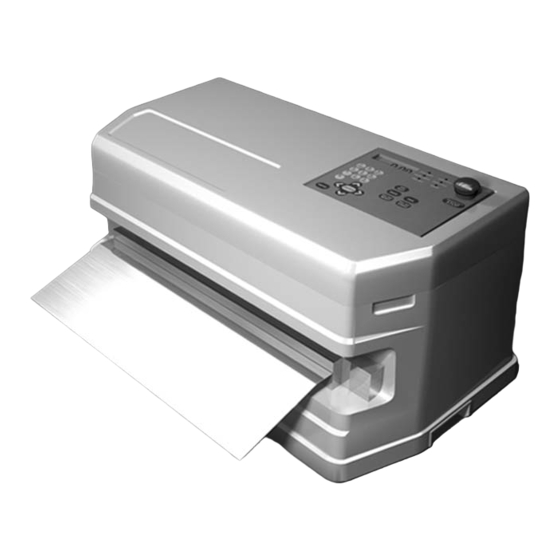
- Page 1 Printed SEP 2019 3rd Edition 3.11E MICROCOMPUTER-CONTROLLED SEALER FOR STERILIZABLE BAGS ME DICAL POU C H SEA L ER MS-451 PV OPERATING INSTRUCTIONS 0493200A www.vanderstahl.com...
- Page 2 MS-451PV Operating Instruction 3.11E Foreword Thank you for purchasing the MS-451PV sealer. Please read all of the safety and operating instructions before operating this machine. Periodic maintenance and proper operation are necessary to ensure safety when using this impulse sealer. Keep this manual on hand when operating the sealer.
- Page 3 MS-451PV Operating Instruction 3.11E About the warning labels The following marks are used in this manual to easily identify the conditions of risks, damages, or some tips for the optimal use of your unit. ・ ・ Minor injuries or damages to the unit may occur when the instruction is Caution ignored. ...
-
Page 4: Table Of Contents
MS-451PV Operating Instruction 3.11E Table of Contents 1 Specifications ……………………………………………………………………………………………… 6 2 Proper Operating Boundaries for MS-451PV …………………………………………………………… 7 3 Package Contents …………………………………………………………………………………………… 7 4 Replacement Parts ………………………………………………………………………………………… 8 5 Warning-Caution Label Location and Content ………………………………………………………… 8 6 Operating Precautions …………………………………………………………………………………… 10 7 Major Parts and Function …………………………………………………………………………………... - Page 5 MS-451PV Operating Instruction 3.11E 11 Details of the Inspection Modes ……………………………………………………………………… 46 11-1 When the Inspection Mode starts - Inspection Mode 1 and 2 - ………………………………………………………………… 46 11-2 How to start Inspection Mode - Inspection Mode 3 - …………………………………………………………………………… 51 11-3 When the Inspection Mode starts - Inspection Mode 4 - …………………………………………………………………………...
-
Page 6: Specifications
MS-451PV Operating Instruction 3.11E 1 Specifications Sealer AC 110V 50/60HZ Power the rated voltage. Power consumption 1400W / Stand by 30W Power cord Machine dimensions W 630 × D 340× H 300 mm (without a table) Machine weight 36 kg Effective seal length 450 mm (-0 to +10 mm) 10 mm (±... -
Page 7: Proper Operating Boundaries For Ms-451Pv
MS-451PV Operating Instruction 3.11E 2 Proper Operating Boundaries for MS-451PV The impulse sealer is a machine which sends strong electric current quickly to the thin ribbon heater, which presses against the film and instantly heat seals the package. Though this machine yields superior quality sealing, it is not compatible with films thicker than that indicated in the diagram below, sponge-like sheets, and materials which are not able to withstand high heat. -
Page 8: Replacement Parts
MS-451PV Operating Instruction 3.11E 4 Replacement Parts Routine maintenance parts, which will need to be replaced after extensive use, are sold individually as detailed below. Replacement parts can be purchased through Van der Stahl Scientific. Parts Number Parts Name Sales Unit... - Page 9 MS-451PV Operating Instruction 3.11E Bottom of the control unit On the body frame W1263 W1263 On the pressure lever On the PTT W1262 W1260 W1262 Sealer cover front W1260 W1262 If Warning-caution labels peel off or are lost, please purchase the proper labels and place them in the appropriate location.
-
Page 10: Operating Precautions
Do not use parts other than those specified Warning When replacing parts, always use only specified parts sold through Van der Stahl Scientific.We are not responsible for malfunctions caused by the use of unspecified parts. - Page 11 MS-451PV Operating Instruction 3.11E Do not use in the following places Caution Do not operate machine in the following places since there is a danger of malfunction Dusty locations. Locations not within normal temperatures. Locations with highly humidity. Do not place hands in the sealing area Caution With prolonged use, the sealing area will retain heat and become hot.
- Page 12 MS-451PV Operating Instruction 3.11E Set the cooling temperature depending on the film Cooling process is important when using an impulse sealer. After the film is heated, the film must cool with the frame and pressure lever in the closed position. Setting the cooling temperature excessively low will decrease the work productivity.
- Page 13 MS-451PV Operating Instruction 3.11E...
-
Page 14: Major Parts And Function
MS-451PV Operating Instruction 3.11E 7 Major Parts and Function Frame cover Visual inspection unit (VIU) Open the cover when Used for inspecting the operating inspection mode. sealing. Control unit Setting sealing conditions etc.. See “10 How to Set the Body cover for the details. - Page 15 MS-451PV Operating Instruction 3.11E Control Unit Display monitor 1 Set conditions etc. are displayed. 2 Error message is displayed. Number key Used for inputting the seal conditions, dates, IDs, and registering passwords. Letters and numbers can be input when registering IDs.
-
Page 16: Proper Use Of The Sealer
MS-451PV Operating Instruction 3.11E 8 Proper Use of the Sealer Use only as described in this manual. There is a risk of danger and malfunctions may result if the machine is used not in accordance with this manual. 8-1 Secure the work place Place the machine on a flat, horizontal surface and secure an appropriate workbench. - Page 17 MS-451PV Operating Instruction 3.11E 8-5 Plugging in the electrical power cord The power cord is located on the left side of the machine, when facing toward it. Make sure the electrical outlet has adequate current carrying capacity as described at Insert the electric power plug fully into the wall outlet.
- Page 18 MS-451PV Operating Instruction 3.11E With the operation mode, the display will show the 1: DATE<00 : 00 : 00> current date and time as in the right illustration. TIME <00 : 00 : 00> TIPS If the Inspection Mode is activated, the inspection mode may start running when turning ON the power switch. Please follow the procedure referring to “11 Details of 46 .
- Page 19 MS-451PV Operating Instruction 3.11E Caution After operating the machine for a while, sealing area becomes hot and the danger of burning increases. Do not put fingers into the sealing area where a strong pressure is applied. When the foreign object is put between the pressure levers or the microswitch does not turn on within 0.35 sec., the lever releases the pressure automatically.
-
Page 20: Initial Settings Of The Control Unit (Factory Setting)
MS-451PV Operating Instruction 3.11E 9 Initial Settings of the Control Unit (Factory Setting) The sealer is shipped from the factory with the following default settings. For details on how to change the settings, please refer to “10 How to Set the Control Unit.” MENU 1 TEMP. -
Page 21: How To Set The Control Unit
MS-451PV Operating Instruction 3.11E 10 How to Set the Control Unit 10-1 [MENU 1] Set the sealing condition MENU1 Set the sealing parameters – heating temperature, heating time, and cooling temperature. Press the key to show the MENU 1 MENU 1 on the display. - Page 22 MS-451PV Operating Instruction 3.11E After inputting the parameters, press the 1: H C T key to confirm the setting. The 140F 140F 0.0s display will return to the MENU display. MENU 1 TEMP.SETTING Register multiple seal patterns You may register up to 5 seal patterns. 5: H C T 140F 140F 0.0s Press the key when the right display is...
-
Page 23: Menu 2] How To Register The Administrator Id
MS-451PV Operating Instruction 3.11E 10-2 [MENU 2] How to register the Administrator ID MENU2 Set the Administrator ID MENU 2 Press the key to show the OPERATOR SETTING MENU 2 on the display. 00 : 0 : <ADMINIST> Administrator ID Administrator ID is <000000>... -
Page 24: Set The Administrator Password
When registering the Operator password, be sure to note it and keep it in a safe place. If you forget your password, you may not be able to operate the machine. Van der Stahl cannot recognize or manage passwords that customers have set. -
Page 25: Menu 2] How To Register The Operator Id
MS-451PV Operating Instruction 3.11E 10-3 [MENU 2] How to register the Operator ID Once the Administrator ID is set, the display automatically shows setting for Operator ID as indicated below. 01 : 0 : <OPERAT01> Operator name The name may be <000001>... -
Page 26: Register The Operator's Name
If you forget your password, you e.g.) may not be able to operate the machine. 00 : 1 : <OPERATO1> <123456> Van der Stahl cannot recognize or manage passwords that customers have set. 02 : 0 : <OPERAT02> <000000>... -
Page 27: Menu 3] Set The Inspection Mode
MS-451PV Operating Instruction 3.11E After each Operator ID is registered, press e.g.) key to complete the setting process. 00 : 1 : <OPERATO1> <123456> The display for registering the next Operator ID appears. Press the key to move the cursor and input a name consisting of eight characters. 02 : 0 : <OPERAT02>... - Page 28 MS-451PV Operating Instruction 3.11E MENU 3 Set the inspection mode MENU 3 Press the key several times INSPECTION MODE until the MENU 3 indicated below is shown on the display. INSPECTION. Press the key. The display will show 1 the following. MODE1 - Inspection begins when the date Press the key to show inspection changes.
-
Page 29: How To Set The Inspection Mode 1
MS-451PV Operating Instruction 3.11E 10-4-1 How to set the Inspection Mode 1 In the Inspection Mode 1, the sealer will automatically switch to the Inspection Mode when the date changes. TIPS ・ ・ next time the power is turned on. ・... -
Page 30: How To Set The Inspection Mode 3
MS-451PV Operating Instruction 3.11E (10-4-2 How to set the Inspection Mode 2 Cont’d) The number can be set from 0000 to 9999 INSPECTION. in arbitrary increments. Input the desired 2 0001 number with the numeric keys. When you want to perform inspection every 5 seals, input 0005. -
Page 31: How To Set The Inspection Mode 4
MS-451PV Operating Instruction 3.11E 10-4-4 How to set the Inspection Mode 4 In Inspection Mode 4, the Inspection Mode will automatically run by timer set by the user. You can set maximum 3 timers per day. Only with the inspection mode 4, you can also set the number of times for sealing, VIU inspection, and peel tensile testing respectively. - Page 32 MS-451PV Operating Instruction 3.11E (10-4-4 How to set the Inspection Mode 4 Cont’d) Input the desired time with the numeric INSPECTION TIME keys in 24-hour system in military time. NO.1. 1. 00:00 The hour is shown using the TIPS e.g., 11 p.m. appears as 23:00. After inputting the desired time, press the key to confirm the setting.
-
Page 33: Menu 4] Seal Counter
MS-451PV Operating Instruction 3.11E 10-5 [MENU 4] Seal counter The seal count number matches the sequential number used for outputting data into the computer. The counting capacity is from 0 to 9,999. Caution Under the inspection Mode 2, do not reset the counter since it will require resetting of inspection Mode 2. -
Page 34: Menu 6] Select The Unit
MS-451PV Operating Instruction 3.11E 10-7 [MENU 6] Select the unit You can select the unit to be displayed. The unit you set will be reflected on all items that require unit setting. Press the key so that MENU 6 MENU 6 as in the right illustration is UNIT SELECT shown on the display. -
Page 35: Menu 8] Set The Minimum Seal Pressure
MS-451PV Operating Instruction 3.11E Press when the desired mode is shown on the display. The setting is completed. Press the key to return to the operation screen. TIPS The display unit will differ according to the unit setting. The example below shows unit set at Kg. -
Page 36: Menu 9] Change The Temperature Unit
MS-451PV Operating Instruction 3.11E 10-10 [MENU 9] Change the temperature unit The unit setting for sealing temperature can be changed to Centigrade (C) or Fahrenheit (F). Press the key so that MENU 9 MENU 9 as in the right illustration is TEMPERATURE shown on the display. -
Page 37: Menu 11] Set The Time
MS-451PV Operating Instruction 3.11E After inputting the data, press the key. The setting is completed. Press the key to return to the operation screen. Pressing the without pressing the key will result in the setting being inactivated. 10-12 [MENU 11] Set the time Set or change the time. -
Page 38: Menu 12] Adjust The Time
MS-451PV Operating Instruction 3.11E 10-13 [MENU 12] Adjust the time The second will be set to 00. This is used for adjusting the time. MENU 12 Press the key so that TIME ADJUST MENU 12 as in the right illustration is shown on the display. Example) Press the key at 10 : 15 : 23 to adjust the time to 10 : 15 : 00. -
Page 39: Menu 14] Monitor The Temperature In Real Time
MS-451PV Operating Instruction 3.11E 10-15 [MENU 14] Monitor the temperature in real time The temperature measured by the temperature sensor is displayed in real time. Press the key so that MENU 14 MENU 14 as in the right illustration is TEMP. MONITOR shown on the display. -
Page 40: Menu 15] Monitor The Pressure To The Sealing Pressure Load-Cell
MS-451PV Operating Instruction 3.11E 10-16 [MENU 15] Monitor the pressure to the sealing pressure load-cell You can monitor the pressure applied to the seal load-cell in real time. Press the key so that MENU 15 MENU 15 as in the right illustration is SEAL LOAD-CELL shown on the display. -
Page 41: Menu 16] Monitor The Pressure To The Ptt Load-Cell
MS-451PV Operating Instruction 3.11E 10-17 [MENU 16] Monitor the pressure to the PTT load-cell You can monitor the pressure applied to PTT-50 load-cell in real time. Press the key so that MENU 16 MENU 16 as in the right illustration is PEEL LOAD-CELL shown on the display. -
Page 42: Menu 17] Monitor The Seal Pressure To The Seal Levers
MS-451PV Operating Instruction 3.11E 10-18 [MENU 17] Monitor the seal pressure to the seal levers The calculated value of the seal pressure to the seal levers is displayed in real time. Press the key so that MENU 17 MENU 17 as in the right illustration is FORCE MONITOR shown on the display. -
Page 43: Menu 19] Set The Continuous Operation Mode
MS-451PV Operating Instruction 3.11E 10-20 [MENU 19] Set the continuous operation mode MENU19 Press the key so that CONTINUOUS MODE MENU 19 as in the right illustration is shown on the display. SET INTERVAL Press the key. The right display will 0.0s shown on the screen. -
Page 44: Menu21 Data View
MS-451PV Operating Instruction 3.11E 10-22 [MENU 21] Data view With this menu, you can check the stored MENU21 test data with the MS-451PV. DATA VIEW Press the keys so that MENU 21 as in the right illustration is shown on the display. Press the DATA VIEW to select the menu. - Page 45 MS-451PV Operating Instruction 3.11E Check peel data Press the key when PEEL DATA is DATA VIEW displayed on the screen. PEEL DATA Select the desired peel test data using PEEL DATA PEEL DATA keys and press the key. Now you 043016 10:30:30 043016 10:31:30 can check the detail of individual peel test...
-
Page 46: Details Of The Inspection Modes
MS-451PV Operating Instruction 3.11E 11 Details of the Inspection Modes 11-1 When the Inspection Mode starts - Inspection Mode 1 and 2 - TIPS The Inspection Modes 1~4 can only be utilized when the Administrator ID and Operator ID are both activated, and the Operator ID is logged in. - Page 47 MS-451PV Operating Instruction 3.11E Insert the sealed, sterilized bag for inspection and visually inspect the sealing surface. Inserting a film at that time will change the VIU INSPECTION text on the display to FILM ON as shown FILM ON on the right illustration. FILM SET ERROR 60 PUSH START KEY...
- Page 48 MS-451PV Operating Instruction 3.11E To perform a Peel Tensile Test on a test sterilized bag that has passed the VIU inspection, cut it a specimen as specified in ASTM 88. TIPS By using a cutting template, which is included in the accessories, you can easily cut the film in the size of 1 inch width.
- Page 49 MS-451PV Operating Instruction 3.11E Turn the star knobs to loosen the thin-film grips. Insert the cut, film portion of the sterilized bag (the end of the test piece that is 0.7 inch from the sealed area) into the thin-film grip of the peel tester (as circled in the right illustration).
- Page 50 MS-451PV Operating Instruction 3.11E Instructions for handing load-cell Caution if a force exceeding rated capacity is applied to the measuring axis or if the axis is twisted at the time of loosening, tightening or attaching the thin-film grips regardless of the power being on or off.
-
Page 51: How To Start Inspection Mode - Inspection Mode 3
MS-451PV Operating Instruction 3.11E 11-2 How to start Inspection Mode - Inspection Mode 3 - In Inspection Mode 3, you can press the button at any time to switch to the inspection mode. TIPS The Inspection Modes 1~4 can only be utilized when the Administrator ID and Operator ID are both activated, and the Operator ID is logged in. -
Page 52: When The Inspection Mode Starts - Inspection Mode 4
MS-451PV Operating Instruction 3.11E 11-3 When the Inspection Mode starts - Inspection Mode 4 - In Inspection Mode 4, the Inspection Mode will automatically run by timer set by the customer. You can set maximum 3 timers per day. Only with the inspection mode 4, you can also set the number of times for sealing, VIU inspection, and peel tensile testing respectively. - Page 53 MS-451PV Operating Instruction 3.11E If you set to perform VIU tests multiple times, the next display for the VIU test will be shown on the screen. Please perform VIU tests until it moves to the PEEL test. VIU 02 / 02 FILM OFF VIU 02 / 02 Press if there is no defects on FILM ON...
- Page 54 MS-451PV Operating Instruction 3.11E TIPS In the Inspection Mode 4, the warning message “ACTIVE INSPECTION IS ACTIVE INSPECT SKIPPED” will be shown in the IS SKIPPED following cases: Push any key to start the Inspection Mode [Case 1] Turn OFF the power switch INSPECTION ↓...
-
Page 55: Daily Inspection For Ptt-50
MS-451PV Operating Instruction 3.11E 12 Daily Inspection for PTT-50 MS-451PV is installed with the function to regularly inspect the peel strength measurement ability. Regularly perform this inspection to ensure there is no abnormality in the strength measurement before starting the operation. ... - Page 56 MS-451PV Operating Instruction 3.11E Set the tension spring set jig and tension spring as in the following directions. How to install the tension spring jig set Install the tension spring set jig to the grip as in the Catch below illustration and set the catch. Make sure the lever is in the clamping Caution position.
- Page 57 MS-451PV Operating Instruction 3.11E After setting the tension spring, press the key. The screen will show the right display and the DAILY INSPECTION grip base moves slowly to the measurement **.**mm **.*N origin. The grip base stops at the origin (5mm) extending the tension spring.
-
Page 58: Replacing The Routine Maintenance Parts
Follow directions on this manual when replacing parts. Replacing parts in the way ignoring this Warning manual could cause malfunction of the machine as well as electrocution and fire. Always use only specified parts sold through Van der Stahl Scientific. Unspecified parts may Warning cause malfunction of the machine. -
Page 59: Preparation Before Replacing Parts
MS-451PV Operating Instruction 3.11E 13-1 Preparation before replacing parts When replacing parts, remove the frame cover and lift up and push over the clamping lever and control unit for easier replacement. Frame cover First, remove the VIU lends if it is set in the unit. - Page 60 MS-451PV Operating Instruction 3.11E Next, loosen the knurled nut on the right side of Control unit the control unit, and push the control unit over Pressure adjusting nut to the other side. (See the picture on the right.) Next, loosen the screw that secures the pressure adjuster nut by turning it counter-clockwise.
-
Page 61: Replacing The Zone (Center-Dry) Tape
MS-451PV Operating Instruction 3.11E 13-2 Replacing the zone (center-dry) tape You will need: Scissors, Phillips screwdriver Replace when: The zone (center-dry) tape breaks, Non-adhesive area burns, or when the seal becomes messy, etc. Adhesive area The zone (center-dry) tape is sold individually. Remove the old zone (center-dry) tape, starting from the edge. -
Page 62: Replacing The Heating Element
Caution For safety, always attach the electrode cover after replacing the heating element. Always use a Van der Stahl Scientific specified special heating element for replacement. Using a heating element other than the designated heating element may cause the transformer to be heat- damaged. -
Page 63: Replacing Glass Tape And Sarcon Sheet
MS-451PV Operating Instruction 3.11E 13-4 Replacing glass tape and Sarcon sheet 460mm You will need: Scissors, Phillips screwdriver Replace when: The heating element breaks often, the Sarcon Sheet seal becomes messy, etc. Electrode The glass tape and Sarcon Sheet are sold individually. 470mm Carefully read the respective replacement instructions on the zone tape, heating element... -
Page 64: Replacing The Pressure Rubber
MS-451PV Operating Instruction 3.11E 13-5 Replacing the pressure rubber You will need: Phillips screwdriver Pressure-adjusting nut Replace the pressure rubber every 6 months or every year Small Lever Remove the frame cover referring to “Preparation before replacing parts.” Sealing Pressure load-cell (The ledge part should come upward.) Loosen the pressure-adjusting nut referring to... -
Page 65: How To Replace The Microswitch
MS-451PV Operating Instruction 3.11E 13-7 How to replace the microswitch You will need: Phillips screwdriver The microswitch is sold individually. Please refer to 83) to see where the microswitch is attached. Warning Always unplug the power cord from the outlet when replacing the microswitch. Remove the two screws that secure the Microswitch terminals microswitch, and pull out the microswitch... -
Page 66: Replacing The Temperature Sensor
MS-451PV Operating Instruction 3.11E 13-8 Replacing the temperature sensor Temperature sensor module Caution When replacing the temperature sensor, Screw B be careful not to damage the temperature sensor Caution Be sure to pay utmost care and operate accurately as misaligning or forgetting to attach the temperature sensor will prevent Temp sensor fixing plate... - Page 67 MS-451PV Operating Instruction 3.11E plate (the A-2 side) while lightly pulling the sensor toward the temperature sensor module so Heating element that there is no slacking between the temperature sensor fixing plate (the A-1 side) and the temperature sensor fixing plate (the A-2 Temperature-sensing part side.) Install the temperature sensor ...
-
Page 68: Replacing Battery
MS-451PV Operating Instruction 3.11E 13-9 Replacing battery You will need: Phillips screwdriver 1 DATE<07.08.16> Replace when “BATTERY ERROR” or “TIMER BATTERY ERROR ERROR” is displayed as in the 1 DATE<07.08.16> illustration on the right. TIMER ERROR CR Coin Lithium Battery contains Warning Perchlorate Material – special handling may apply. -
Page 69: Replacing Fuse
MS-451PV Operating Instruction 3.11E After replacing the battery, "TIME ERROR" 1 DATE<07.08.16> will be displayed. TIMER ERROR Adjust the date and time as they will be initialized. If "TIME ERROR" displays even Attention after replacing the battery and adjusting the date and time, substrate failure may be suspected. -
Page 70: Adjusting Each Parts
MS-451PV Operating Instruction 3.11E 14 Adjusting Each Parts 14-1 Adjusting the sealing pressure Adjust the "Pressure Strength (High – Normal)" indicated on the sealing pressure adjuster dial using the indicator on the small lever. Loosen the screw that secures the pressure adjuster dial. -
Page 71: Adjusting Sensitivity Volume On Viu Photo Sensor
MS-451PV Operating Instruction 3.11E Attention Operating while the dial is turned excessively counterclockwise (the direction for handling thicker the sound of the clamping lever movement. 14-2 Adjusting sensitivity volume on VIU photo sensor If you notice the following in regards to the VIU Unit Photo Sensor, adjust the volume control: The display does not change from FILM OFF to FILM ON when film is inserted during VIU... -
Page 72: Optional Items
MS-451PV Operating Instruction 3.11E 15 Optional Items The following optional parts are available separately from the main unit. 15-1 Sealing area safety cover The Sealing Area Safety Cover provides extra safety measures such as preventing fingers from getting caught in the sealing area. Sealing Area Safety Cover Front/right side view Back/right side view... -
Page 73: Touch-Switch Protection Cover
MS-451PV Operating Instruction 3.11E 15-2 Touch-switch protection cover Protecting the touch switch with the touch switch Touch-switch protection cover protection cover provides protection from falling Top cover objects and helps prevent unintended operations caused by such objects, etc. Bottom base How to install: You will need: Phillips screwdriver Magnet sheet... -
Page 74: Film-Cutting Template With Cutting Mat
MS-451PV Operating Instruction 3.11E 15-3 Film-cutting template with cutting mat This is a cutting base for cutting out ASTM88-standard Film-cutting template test pieces (1-inch width) for performing PTT tests. You will need: Box cutter How to install: You will need: a box cutter Caution Be careful not to cut your hands, etc., Standard for... -
Page 75: About The Load-Cell Calibration
MS-451PV Operating Instruction 3.11E 16 About the Load-Cell Calibration Load-cell accuracy will decline with the number of use and passage of time. We recommend you perform one calibration a year so that you may continue to use the load cells in a better condition. -
Page 76: Electric Diagram
MS-451PV Operating Instruction 3.11E 18 Electric Diagram AC110V Fuse Power switch Noise Filter temperature BLACK sensor Micro switch Heater transformer 4P Terminal board Triac Operation board 5 3 1 Main board DC24V Amplifier Amplifier Solenoid Load cell I/O board Sensor Load cell cooling Fan Emergency stop Connector BLACK Sensor Safety circuit board Senser Motor Switch... -
Page 77: Common Problems And Solutions
MS-451PV Operating Instruction 3.11E 19 Common Problems and Solutions In case of machine malfunctioning, please refer to the chart below. Carefully follow the directions in the operating instructions when replacing parts. Please consult your dealer if the problem cannot be resolved even after referring to the chart. Please refer any questions regarding replacement of parts not listed in the operating instructions or adjustment of those parts to your dealer. - Page 78 MS-451PV Operating Instruction 3.11E Problems Check Solutions ※ Replace the shock absorber. Is the shock absorber damaged? The pressure lever bounces back up soon after coming down. Refer to “13-7 How to replace the Is the microswitch installed properly? Heating temperature and time is ---------- Check the temperature sensor.
-
Page 79: Error Messages During Operation
MS-451PV Operating Instruction 3.11E 20 Error Messages during Operation 20-1 Sealing condition related errors Display Problem Solutions Is the microswitch is continuously touched and Solenoid valve is not ON, while the remains in the ON state? “ ERROR No 1 ” microswich is ON ※... -
Page 80: Peel Tensile Tester Related Errors
MS-451PV Operating Instruction 3.11E 20-2 Peel tensile tester related errors Display Problem Solutions Is the maximum and average peel tensile is set properly? Refer to for the details. page 34 Is the heating temperature is set properly? This error is displayed when the Refer to “... -
Page 81: System Related Errors
MS-451PV Operating Instruction 3.11E 20-3 System related errors Display Problem Solutions ※ The electric board may have been broken. This error is displayed when there is “ ERROR No 80 ” defection in writing serial EEPROM. Please contact your local dealer. The battery voltage has decreased. -
Page 82: To Discard
MS-451PV Operating Instruction 3.11E 21 To discard The owner of the equipment is responsible for proper disposal of the equipment. When you need to dispose of the machine, please follow the guidance of your local authority. For further information we advise you to contact your local waste facility. -
Page 83: Exploded View / Parts List
MS-451PV Operating Instruction 3.11E Exploded View / Parts List When ordering spare parts, please consult the exploded view diagram / spare parts list on the following pages and provide both the part name and code number to your local dealer. - Page 84 MS-451PV Exploded Parts View 0493200A MS-451PV Peel Tensile Tester VIU Unit Seal Area Control Unit The parts marked in square are listed either on page 85 or 86.
- Page 85 MS-451PV Exploded Parts View 0493200A MS-451PV Peel Tensile Tester Control Unit DC motor unit ( not included) VIU Unit...
- Page 86 MS-451PV Exploded Parts View 0493200A MS-451PV Sealing Area...
- Page 87 MS-450PV Spare Parts List 0493200A MS-451PV ● Please indicat the part name and number as listed below when placing your order. ● Please specify model name and parts name when there is no code No. Parts Parts Code No. Parts Name Sales Unit Code No. Parts Name Sales Unit 560205 Upper frame cover 1 pc. 560301 Pressure adjusting nut set 1 pc. 560210 Lower frame cover 1 pc. 560004 Small lever 1 pc. 560215 Hinge 2 pcs./set 490800 Pressure rubber 1 pc. 560220 DC power source 1 pc. 560302 Return spring 1 pc. 560230B Load-cell amplifier set 1 pc.
- Page 88 Represented by Y5951 SEP 2019 3rd Edition MS-451PV Series Operating Instructions Ver. 3.11E...
Need help?
Do you have a question about the MS-451 PV and is the answer not in the manual?
Questions and answers