
Related Manuals for Van Der Stahl V-460G Series


Summary of Contents for Van Der Stahl V-460G Series
- Page 1 Printed JAN 2020 4th Edition 4.02E MICROCOMPUTER CONTROLLED TABLETOP NOZZLE TYPE VACUUM & GAS-FLUSHING SEALER V-460G/610G SERIES OPERATING INSTRUCTIONS D TYPE www.vanderstahl.com...
- Page 2 V-460G/610G Series Operating Instructions Ver.4.02E Thank you for purchasing V-460G/610G series sealer! V-460G/610G series is a vacuum/gas-flushing sealer controlled by the microcomputer, which makes possible to set up the various operation patterns that the customers require. This manual explains the terms that is used when setting the seal conditions. Please read this manual thoroughly before use for the better understanding on how to set up/operate the V-460G/610G series.
- Page 3 V-460G/610G Series Operating Instructions Ver.4.02E Foreword Please read all of the safety and operating instructions before operating this machine. Periodic maintenance and proper operation are necessary to ensure safety when using this impulse sealer. Keep this manual on hand when operating the sealer. Set the heating time according to the material and thickness of the film.
-
Page 4: Table Of Contents
V-460G/610G Series Operating Instructions Ver.4.02E Table of Contents 1 Package contents ……………………………………………………………………………………… 7 2 Warning-caution label location and content ……………………………………………………… 8 3 Operating precautions ……………………………………………………………………………… 10 For safe operation ………………………………………………………………………………………………………………………… 10 For smooth operation ……………………………………………………………………………………………………………………… 13 Other safeguards …………………………………………………………………………………………………………………………… 13 About the I-heating element ………………………………………………………………………………………………………………... - Page 5 V-460G/610G Series Operating Instructions Ver.4.02E 8-4-15 Select the circulating gas-flushing mode ………………………………………………………………………………… 52 8-4-16 Setting nozzle stroke ………………………………………………………………………………………………………… 56 8-4-17 Nozzle Auto Return setting ………………………………………………………………………………………………… 57 8-4-18 Maintenance mode …………………………………………………………………………………………………………… 57 8-5 Operation procedures ………………………………………………………………………………………………………………… 58 8-5-1 Operation procedures «SEAL ONLY» ………………………………………………………………………………… 58 8-5-2 Operation procedures «MANUAL VAC + SEAL»...
- Page 6 V-460G/610G Series Operating Instructions Ver.4.02E 15 Common problems and solution………………………………………………………………… 111 15-1 Error display 1 ……………………………………………………………………………………………………………………… 112 14-2 Error display 2 ……………………………………………………………………………………………………………………… 113 15-3 Error display 3 ……………………………………………………………………………………………………………………… 114 15-4 Maintenance mode ………………………………………………………………………………………………………………… 114 16 Consumable parts list …………………………………………………………………………… 115 17 To discard ……………………………………………………………………………………………...
-
Page 7: Package Contents
5 Others Vacuum gauge instruction manual ※ ····1 pc. If anything is missing or damaged, contact Van der Stahl Scientific. Contents of package may vary depending on the machine model you have ordered. ※ For how to operate a vacuum gauge, please refer to the vacuum gauge manual. -
Page 8: Warning-Caution Label Location And Content
V-460G/610G Series Operating Instructions Ver.4.02E 2 Warning-caution label location and content Warning - caution labels are placed in locations where there is a danger of injury to a person or damage to the machine. Label location details are illustrated below. Please check them before beginning operation. Labels not readily apparent are indicated by dotted lines. - Page 9 V-460G/610G Series Operating Instructions Ver.4.02E Warning-Caution label location and content (Cont’d) Body cover and pressure lever When carrying the main unit, do NOT lift it by its seal lever. W1428 W1265 W1264 W1266 Machine right side If warning-caution labels peel off or are lost, please purchase the proper labels and place them in the appropriate location.
-
Page 10: Operating Precautions
V-460G/610G Series Operating Instructions Ver.4.02E 3 Operating precautions For safe operation In an emergency, unplug the power cord Warning immediately The V-460G/610G series incorporates a number of safety devices and is carefully designed to prevent fires or other malfunctions. However, should all of the safety devices fail simultaneously, there is a possibility of the center-dry tape catching fire due to a failure of the heating circuit's tripping mechanism that results in the heating element... - Page 11 V-460G/610G Series Operating Instructions Ver.4.02E When replacing parts, unplug the power plug Warning Maintenance of the machine is important. Parts should be replaced in accordance with the operating instructions. There is a risk of danger if the parts are not replaced properly. Before replacing parts, unplug the machine from the power source.
- Page 12 V-460G/610G Series Operating Instructions Ver.4.02E Do not use in the following places Caution Do not operate the machine in the places with high humidity and/or where the water/vapor can spill on the machine. The machine parts may become rusted. There is a danger of electrocution and/or machine malfunction due to the insulation failure.
-
Page 13: For Smooth Operation
V-460G/610G Series Operating Instructions Ver.4.02E For smooth operation Heating temperature should be set at a minimum Set sealer so that an acceptable seal is completed at the lowest heating temperature. Excessively high heating temperatures will damage the center-dry tape, glass tape and other consumables, as well as result in heating element breakage. -
Page 14: About The I-Heating Element
V-460G/610G Series Operating Instructions Ver.4.02E Run test trials before beginning operation Depending on the type of film being used, heating / cooling conditions will differ. Run test trials to find the optimum sealing condition, especially when trying to find the tightest seal possible. ●... -
Page 15: Outline Of Structure
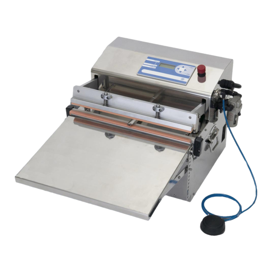
V-460G/610G Series Operating Instructions Ver.4.02E 4 Outline of structure The V-460G/610G is a tabletop impulse sealer equipped 1 Place a pouch Sealing section with nozzles for removing air and gas flushing. Sponge rubber When the nozzles are inserted into a bag, the bag will be securely locked by sponge-rubber strips covering the sealing jaws. -
Page 16: Major Parts And Function
V-460G/610G Series Operating Instructions Ver.4.02E 6 Major parts and function Vacuum gauge Refer to a vacuum gauge manual Control unit included in accessories for the details. Printer outlet Emergency stop switch Frame cover Open the frame cover to perform Lever lock machine maintenance. - Page 17 V-460G/610G Series Operating Instructions Ver.4.02E Control unit ⑧ ④ ⑦ ⑤ ⑥ ③ ⑨ ⑩ ⑪ ⑫ ② ① ① Power button ④⑤⑥⑦ Arrow key Push to turn ON or OFF the power. (When circuit breaker is With the arrow keys, you can increase/decrease numerical ON.) values in each setting.
-
Page 18: Proper Use Of The Sealer
V-460G/610G Series Operating Instructions Ver.4.02E 7 Proper use of the sealer 7-1 Secure the work place For safety and efficient operation, please set the sealer in the appropriate place as described below. Installing the machine on an unstable or Warning inclined surface may cause the overturn of the sealer. -
Page 19: Test Emergency Stop System
If the circuit breaker does NOT turn OFF Warning by pressing the emergency stop switch, follow the below instructions and contact Van der Stahl Scientific. Test button Press a test button of the circuit breaker as in the right illustration. -
Page 20: Set An Air Pedal
V-460G/610G Series Operating Instructions Ver.4.02E 7-4 Set an air pedal Insert an air pedal hose securely into the elbow of the Securely insert main frame air switch located on the right side of the the hose machine. Air hose Body frame air switch with elbow joint Air pedal 7-5 Attach/remove the table and how to... -
Page 21: Nozzle Position Adjustment
V-460G/610G Series Operating Instructions Ver.4.02E 7-6 Nozzle position adjustment ■ Preparation Remove screws Remove two screws that fix the frame cover. Raise the Frame cover frame cover to open it. ■ Adjust nozzle angle You can adjust the nozzle angle according to your packaging needs. - Page 22 V-460G/610G Series Operating Instructions Ver.4.02E ■ Adjust nozzle distance The distance between the two nozzles can be adjusted depending on the size of bags. Loosen the hollow screws on the rear size of nozzle holders to move them. Moving range The maximum distance between the outer ends of two nozzles is 180mm while the minimum distance is 65mm.
-
Page 23: Connect A Gas-Cylinder
V-460G/610G Series Operating Instructions Ver.4.02E 7-7 Connect a gas-cylinder The supply of gas comes from a compressed gas cylinder, which must be provided by the user. Prepare for a gas cylinder with the reducing valve and flow meter. Connect the gas cylinder and gas cock on V-460G/610G using a hose. -
Page 24: Test Sealing
V-460G/610G Series Operating Instructions Ver.4.02E 7-10 Test sealing After setting seal parameters at the control unit, hold a bag by both hands and stretch it tight. Set the bag between seal levers. (Insert vacuum nozzles into the bag if necessary.) Depress the air pedal to proceed the operation. -
Page 25: Control Unit Setting And Operating Procedures
V-460G/610G Series Operating Instructions Ver.4.02E 8 Control unit setting and operating procedures This chapter includes the following sections: Operate the machine with the pre-installed operation patterns This chapter explains how to operate the V-460G/610G series with the pre-installed operation patterns to give you the general idea of how to operate the machine properly. -
Page 26: Operate The Machine With Pre-Installed Operation Patterns
V-460G/610G Series Operating Instructions Ver.4.02E 8-1 Operate the machine with pre-installed operation patterns Four operation patterns introduced in this section are pre-installed to the V-460G/610G series at the time of factory shipment. The sealing parameters of the pre-installed operation patterns (heating temperature etc.) can be Attention changed depending on the customer application. -
Page 27: Sample Operating Procedures : "Seal Only" Operation
V-460G/610G Series Operating Instructions Ver.4.02E 8-1-1 Sample operating procedures : “seal only” operation Operation No.[01] SEAL ONLY The seal parameters set at the time of factory shipment: HT : 140ºC/280ºF, CT : 100ºC/200ºF = See 6 Depress an air pedal If any change has been made to the TIPS control unit setting after factory... -
Page 28: Sample Operating Procedures : "Manual Vacuum + Sealing" Operation
V-460G/610G Series Operating Instructions Ver.4.02E 8-1-2 Sample operating procedures : “manual vacuum + sealing” operation Operation No.[02] VAC & SEAL manual The seal parameters set at the time of factory shipment: HT : 140ºC/280ºF, CT : 100ºC/200ºF Nozzle stroke = N1 = See 7 Place a bag to the sealing area If any change has been made to the... - Page 29 V-460G/610G Series Operating Instructions Ver.4.02E (‘8-1-2 Sample operating procedures : “manual vacuum + sealing” operation’ cont’d) ・ The pressure lever descends completely. (Sealing starts.) ・ After the heating is complete (heating lamp is turned off), cooling lamp turns on. ・ Cooling is complete (cooling lamp turns off).
-
Page 30: Sample Operating Procedure: "Timer Vacuum + Timer Gas-Flushing + Sealing" Operation
V-460G/610G Series Operating Instructions Ver.4.02E 8-1-3 Sample operating procedure: “timer vacuum + timer gas-flushing + sealing” operation Operation No.[03] VAC & SEAL manual = Operation No. [03] 1-GAS / timer The seal parameters set at the time of factory shipment: HT (Heating Temperature) : 140ºC/ 280ºF, CT (Cooling Temperature) : 100ºC/200ºF VT (Vacuuming Time) : 1.0 second, GT (Gas flushing time) : 2.0seconds, Nozzle stroke = N1 = See... - Page 31 V-460G/610G Series Operating Instructions Ver.4.02E (‘8-1-3 Sample operating procedure: “timer vacuum + timer gas-flushing + sealing” operation’ cont’d) ・ Once the time specified in gas-flushing time elapses, gas-flushing finishes and gas-flushing lamp turns OFF. ・ The nozzles withdraw. ・ The pressure lever descends completely.
-
Page 32: Sample Operating Procedure: "2 Cycles Of Timer Vacuum + Timer Gas-Flushing + Sealing" Operation
V-460G/610G Series Operating Instructions Ver.4.02E 8-1-4 Sample operating procedure: “2 cycles of timer vacuum + timer gas- flushing + sealing” operation = Operation No. [04] 2-GAS / Timer The seal parameters set at the time of factory shipment: HT (Heating Temperature) : 140ºC/ 280ºF, CT (Cooling Temperature) : 100ºC/200ºF 1-VT (1st Vacuuming Time) : 1.0second, 2-VT (2nd Vacuuming Time) : 1.0second, 1- GT (1st Gas flushing Time) : 2.0seconds, 2-GT (2nd Gas flushing Time) : 2.0seconds, Nozzle stroke = N1 = See... - Page 33 V-460G/610G Series Operating Instructions Ver.4.02E (‘8-1-4 Sample operating procedure: “2 cycles of 10 Finish operation timer vacuum + timer gas-flushing + sealing” Sealing is complete. Please make sure that the seal is properly performed. operation’ cont’d) When not using the machine for a while, please make sure the followings: ・...
-
Page 34: Register Sample Operation Patterns
V-460G/610G Series Operating Instructions Ver.4.02E 8-2 Register sample operation patterns Maximum 10 operation patterns can be stored in the control unit. Attention If you are going to register over 10 operation patterns, the message “ALL 10 OPERATION PATTERNS ARE ENTERED. DELETE ONE FOR A NEW ENTRY.“ is displayed on the screen. You cannot input a new operation pattern until at least one of the stored operation pattern is deleted. -
Page 35: Sample Case: Register A "Seal Only" Operation Mode
V-460G/610G Series Operating Instructions Ver.4.02E 8-2-1 Sample case: register a “seal only” operation mode TIPS The following operation procedures are for the new machine without any change on the setting. Let’s register “sealing only” operation to operation number [05]. Operation setting : heating temperature 140ºC/280ºF, heating time 0.3 seconds, cooling temperature 100ºC/200ºF. 1 Turn ON the circuit breaker. -
Page 36: Sample Case: Register A "1-Gas Timer Vacuum" Operation Mode
V-460G/610G Series Operating Instructions Ver.4.02E 8-2-2 Sample case: register a “1-GAS timer vacuum” operation mode TIPS The following operation procedures are for the new machine without any change on the setting. Let’s register “1-GAS timer vacuum” operation to operation number [06]. Operation setting : heating temperature 140ºC/280ºF, heating time 0.3 seconds, cooling temperature 100ºC/200ºF. -
Page 37: Explanation Of Terms
V-460G/610G Series Operating Instructions Ver.4.02E 8-3 Explanation of terms This chapter explains the terms used in this manual and basic knowledge about our impulse sealers. Impulse sealer There are four sealing methods depending on your purpose and usage. Sealers refer to machines in general that seal the opening or loose ends of plastic- called heat sealers. - Page 38 V-460G/610G Series Operating Instructions Ver.4.02E vacuuming mode repeated up to 99 times. The alphabet "n" indicates an arbitrary number of other nozzle vacuums the air from a pouch. Gas nozzle Vacuum nozzle Gas nozzle Gas nozzle Vacuum nozzle Gas nozzle Vacuum nozzle Vacuum nozzle Nozzle comes...
-
Page 39: How To Set The Control Unit
V-460G/610G Series Operating Instructions Ver.4.02E 8-4 How to set the control unit Explanation of each key on the control panel The following keys are used to set seal conditions. MENU key = Press to show following menus on the display: “1 Enter,” “2 Change,” “3 Delete,” “4 Nozzle,”... -
Page 40: Seal Counter
V-460G/610G Series Operating Instructions Ver.4.02E Before you start operation, read the following references: The following explains on condition circuit breaker and the power switch are ON. The numeric values on the control unit display is described as “xx” The cursor position is described as . mark on the control unit display indicates the different contents by each operation number. -
Page 41: Delete The Operation Pattern
V-460G/610G Series Operating Instructions Ver.4.02E When one operation number is deleted, 8-4-4 Delete the operation pattern TIPS the following numbers will move You can cancel deletion by pressing the forward automatically. TIPS ] if it has not yet confirmed by E.g.) pressing the [ ] key. -
Page 42: Set Heating Time
V-460G/610G Series Operating Instructions Ver.4.02E The cursor will blink at the first digit of “HT.” The cursor will blink at the first digit of “HT.” When the cursor is at this position, adjust the Press the [ ] key to move the cursor to the heating temperature by pressing: position of heating time “x.xs”. -
Page 43: Set Cooling Temperature
V-460G/610G Series Operating Instructions Ver.4.02E 8-4-7 Set cooling temperature If cooling temperature is set extremely TIPS high, the strong and beautiful seal cannot be made. ■ How to change cooling temperature of Please set the sufficient cooling the currently displayed operation temperature for your film. -
Page 44: Select The Vac + Seal Mode
V-460G/610G Series Operating Instructions Ver.4.02E The below display will be shown on the ■ When entering a new operation: screen. >> Place the cursor to “1 Enter” using the [ [0 x] SELE CT M ODE ] keys. Press the [ ] key to select 1 SEA L ... -
Page 45: Manual Vacuum Mode
V-460G/610G Series Operating Instructions Ver.4.02E 8-4-10 Manual vacuum mode 8-4-11 Timer vacuuming mode With the manual vacuuming mode, the With the manual vacuuming mode, the TIPS TIPS vacuuming stops when a foot pedal is vacuum level is determined by setting depressed. -
Page 46: Vacuum Gauge Vacuuming Mode
V-460G/610G Series Operating Instructions Ver.4.02E (“8-4-11 Timer vacuuming mode” cont’d) Press the [ ] key. The cursor will blink at Set seal parameters referring to the Attention the first digit of “VAC GAUGE”. When the chapters below. cursor is at this position, adjust the vacuum time by pressing: page 41) [... -
Page 47: Select The 1-Gas Mode
V-460G/610G Series Operating Instructions Ver.4.02E Set gas-flushing time with 1-GAS mode 8-4-13 Select the 1-GAS mode The below display will be shown. Referring to “8-4-3 Register/change the , place the [ 0 ] ▼▲ CH G Mo ve Nx cursor to “3 1-GAS” by pressing the [ ] key G s ec... -
Page 48: Select The N-Gas Mode
V-460G/610G Series Operating Instructions Ver.4.02E ■ Set vacuuming and gas-flushing time 8-4-14 Select the n-GAS mode with the n-GAS mode Referring to “8-4-3 Register/change the When MANUAL VAC mode is selected , place the cursor to “4 n-GAS” by pressing the [ ] key The below display will be shown. - Page 49 V-460G/610G Series Operating Instructions Ver.4.02E (“8-4-14 Select the n-GAS mode” >>>When MANUAL VAC mode is selected” cont’d) When TIMER VAC mode is selected Next, set the number of vacuuming and gas- The below display will be shown. flushing cycles. [ 0 ]...
- Page 50 V-460G/610G Series Operating Instructions Ver.4.02E (“8-4-14 Select the n-GAS mode>>>When TIMER VAC mode is selected” cont’d) Move the cursor to the first digit of the last (=n Move the cursor to the first digit of gas timer times) vacuum timer “xxVT xx.x sec” using “G xx.x sec,”...
- Page 51 V-460G/610G Series Operating Instructions Ver.4.02E (“8-4-14 Select the n-GAS mode” cont’d) When VACUUM GAUGE VAC mode is Move the cursor to the first digit of gas timer selected “G xx.x sec,” where you can set the gas- flushing time from the first up to the last (n The below display will be shown.
-
Page 52: Select The Circulating Gas-Flushing Mode
V-460G/610G Series Operating Instructions Ver.4.02E 8-4-15 Select the circulating gas-flushing mode Move the cursor to the first digit of the last (=n times) vacuum gauge setting “xxVT xx.x sec” TIPS With circulating gas-flushing mode, using the [ ] key. vacuuming and gas flushing are Adjust the gas-flushing time by pressing: conducted simultaneously. - Page 53 V-460G/610G Series Operating Instructions Ver.4.02E (“8-4-15 Select the circulating gas-flushing mode” cont’d) ■ Set vacuuming and gas-flushing time Set the circulating gas-flushing time. Move with the circulating gas-flushing mode the cursor to the first digit of circulating-gas timer “G xx.x sec” using the [ ] key.
- Page 54 V-460G/610G Series Operating Instructions Ver.4.02E When TIMER VAC mode is selected Move the cursor to the first digit of first gas timer “G xx.x sec,” The below display will be shown. Adjust the gas-flushing time by pressing: [ 0 ] ▼▲ C H G M o ve ...
- Page 55 V-460G/610G Series Operating Instructions Ver.4.02E Using the [ ] key, move the cursor to the first Set the second gas-flushing time. Move the cursor to the first digit of second gas timer digit of vacuum level setting “1VG xx.x kPa.” “G xx.x sec”...
-
Page 56: Setting Nozzle Stroke
V-460G/610G Series Operating Instructions Ver.4.02E 8-4-16 Setting nozzle stroke Set the circulating gas-flushing time. Move the cursor to the first digit of circulating-gas How to change the nozzle stroke of the timer “G xx.x sec” using the [ ] key. currently displayed operation pattern: Adjust the circulating gas time by pressing: >>... -
Page 57: Nozzle Auto Return Setting
V-460G/610G Series Operating Instructions Ver.4.02E 8-4-17 Nozzle Auto Return setting 8-4-18 Maintenance mode Press the [ ] key and show the following Nozzle Auto Return is ON with the Attention display on the screen. default factory setting. S E L E C T / ME N U = E S C 1 ... -
Page 58: Operation Procedures
V-460G/610G Series Operating Instructions Ver.4.02E 8-5 Operation procedures This chapter is intended to provide a good understanding of the total 13 different sealing methods. Select a sealing method to meet your needs, including selecting to best suit the characteristics of the packaged material and to obtain your desired packaging finish. - Page 59 V-460G/610G Series Operating Instructions Ver.4.02E ("SEAL ONLY" operation cont’d) A pressure lever closes (sealing starts). Heating lamp turns ON. After heating is finished, heating lamp is turned OFF and cooling lamp turns ON. Depress an air pedal. Cooling finishes and the cooling lamp turns OFF. Sealing process is complete, and the pressure lever opens.
-
Page 60: Operation Procedures "Manual Vac + Seal
V-460G/610G Series Operating Instructions Ver.4.02E 8-5-2 Operation procedures «MANUAL VAC + SEAL» Display Operation No. Nozzle stroke ※ Temperature unit may be displayed in Fahrenheit depending on the machine model. [ ] ▼▲ C H G M o ve N ... - Page 61 V-460G/610G Series Operating Instructions Ver.4.02E (“Manual vacuum” operation cont’d) A pressure lever descends and fastens a pouch with sponge rubbers. When the lever is being lowered, removing foot from the Depress the air pedal. (2nd) Attention footswitch will raise the lever from its lowered position. Vacuuming starts and the vacuum lamp turns ON.
-
Page 62: Operation Procedures "Timer Vac + Seal
V-460G/610G Series Operating Instructions Ver.4.02E 8-5-3 Operation procedures «TIMER VAC + SEAL» Display Operation No. Nozzle stroke ※ Temperature unit may be displayed in Fahrenheit depending on the machine model. [ ] ▼▲ C H G M o ve N V AC ... - Page 63 V-460G/610G Series Operating Instructions Ver.4.02E (“Timer vacuum” operation cont’d) A pressure lever descends and fastens a pouch with sponge rubbers. When the lever is being lowered, removing foot from the Depress the air pedal. (2nd) Attention footswitch will raise the lever from its lowered position. When the air pedal is depressed for the third time, the following procedures (from 1 to 7) are performed automatically.
-
Page 64: Operation Procedures "Vacuum Gauge Vac + Seal
V-460G/610G Series Operating Instructions Ver.4.02E 8-5-4 Operation procedures «VACUUM GAUGE VAC + SEAL» Display Operation No. Nozzle stroke ※ Temperature unit may be displayed in Fahrenheit depending on the machine model. [ ] ▼▲ C H G M o ve N VAC ... - Page 65 V-460G/610G Series Operating Instructions Ver.4.02E (“Vacuum gauge vacum” operation cont’d) A pressure lever descends and fastens a pouch with sponge rubbers. When the lever is being lowered, removing foot from the Depress the air pedal. (2nd) Attention footswitch will raise the lever from its lowered position. When the air pedal is depressed for the third time, the following procedures (from 1 to 7) are performed automatically.
-
Page 66: Operation Procedures "1-Gas: Manual Vac + Gas + Seal
V-460G/610G Series Operating Instructions Ver.4.02E 8-5-5 Operation procedures «1-GAS: MANUAL VAC + GAS + SEAL» Display Operation No. Nozzle stroke ※ Temperature unit may be displayed in Fahrenheit depending on the machine model. [ ] ▼▲ C H G M o ve ... - Page 67 V-460G/610G Series Operating Instructions Ver.4.02E (“1-GAS: MANUAL VAC + GAS + SEAL” operation cont’d) A pressure lever descends and fastens a pouch with sponge rubbers. When the lever is being lowered, removing foot from the Depress the air pedal. (2nd) Attention footswitch will raise the lever from its lowered position.
-
Page 68: Operation Procedures "1-Gas: Timer Vac + Gas + Seal
V-460G/610G Series Operating Instructions Ver.4.02E 8-5-6 Operation procedures «1-GAS: TIMER VAC + GAS + SEAL» Display Operation No. Nozzle stroke ※ Temperature unit may be displayed in Fahrenheit depending on the machine model. [ ] ▼▲ C H G M ov e ... - Page 69 V-460G/610G Series Operating Instructions Ver.4.02E (“1-GAS: TIMER VAC + GAS + SEAL” operation cont’d) A pressure lever descends and fastens a pouch with sponge rubbers. When the lever is being lowered, removing foot from the Depress the air pedal. (2nd) Attention footswitch will raise the lever from its lowered position.
-
Page 70: Operation Procedures "1-Gas: Vacuum Gauge Vac + Gas + Seal
V-460G/610G Series Operating Instructions Ver.4.02E 8-5-7 Operation procedures «1-GAS: VACUUM GAUGE VAC + GAS + SEAL» Display Operation No. Nozzle stroke ※ Temperature unit may be displayed in Fahrenheit depending on the machine model. [ ] ▼▲ C H G M o ve ... - Page 71 V-460G/610G Series Operating Instructions Ver.4.02E (“1-GAS: VACUUM GAUGE VAC + GAS + SEAL” operation cont’d) A pressure lever descends and fastens a pouch with sponge rubbers. When the lever is being lowered, removing foot from the Depress the air pedal. (2nd) Attention footswitch will raise the lever from its lowered position.
-
Page 72: Operation Procedures "N-Gas: Manual Vac + Gas + Seal
V-460G/610G Series Operating Instructions Ver.4.02E 8-5-8 Operation procedures «n-GAS: MANUAL VAC + GAS + SEAL» Display (The alphabet "n" indicates an arbitrary number of times to repeat vacuuming and gas-flushing cycles.) Operation No. Vacuum mode: manual From first to penultimate The number of times to vacuuming cycles. - Page 73 V-460G/610G Series Operating Instructions Ver.4.02E (“n-GAS: MANUAL VAC + GAS + SEAL” operation cont’d) Place a pouch to the seal area and insert the nozzles in it. Stretch the Place a pouch to the seal area. pouch out by pulling both sides by hands. A pressure lever descends and fastens a pouch with sponge rubbers.
-
Page 74: Operation Procedures "N-Gas: Timer Vac + Gas + Seal
V-460G/610G Series Operating Instructions Ver.4.02E 8-5-9 Operation procedures «n-GAS: TIMER VAC + GAS + SEAL» Display (The alphabet "n" indicates an arbitrary number of times to repeat vacuuming and gas-flushing cycles.) Operation No. Vacuum mode: timer From first to penultimate The number of times to vacuuming cycles. - Page 75 V-460G/610G Series Operating Instructions Ver.4.02E (“n-GAS: TIMER VAC + GAS + SEAL” operation cont’d) Depress an air pedal. (1st) Place a pouch to the seal area and insert the nozzles in it. Stretch the Place a pouch to the seal area. pouch out by pulling both sides by hands.
-
Page 76: Operation Procedures "N-Gas: Vacuum Gauge Vac + Gas + Seal
V-460G/610G Series Operating Instructions Ver.4.02E 8-5-10 Operation procedures «n-GAS: VACUUM GAUGE VAC + GAS + SEAL» Display (The alphabet "n" indicates an arbitrary number of times to repeat vacuuming and gas-flushing cycles.) Operation No. Vacuum mode: vac gauge From first to penultimate The number of times to vacuuming cycles. - Page 77 V-460G/610G Series Operating Instructions Ver.4.02E (“n-GAS: VACUUM GAUGE VAC + GAS + SEAL” operation cont’d) Depress an air pedal. (1st) Place a pouch to the seal area and insert the nozzles in it. Stretch the Place a pouch to the seal area. pouch out by pulling both sides by hands.
-
Page 78: Operation Procedures "Circulate: Manual Vac + Gas + Seal
V-460G/610G Series Operating Instructions Ver.4.02E 8-5-11 Operation procedures «CIRCULATE: MANUAL VAC + GAS + SEAL» Display Operation No. [ ] ▼▲ C H G Mo v e N Nozzle stroke First gas-flushing timer Vacuum mode: manual 1V MAN U AL G ... - Page 79 V-460G/610G Series Operating Instructions Ver.4.02E (“CIRCULATE: MANUAL VAC + GAS + SEAL” operation cont’d) A pressure lever descends and fastens a pouch with sponge rubbers. When the lever is being lowered, removing foot from the Depress the air pedal. (2nd) Attention footswitch will raise the lever from its lowered position.
-
Page 80: Operation Procedures "Circulate: Timer Vac + Gas + Seal
V-460G/610G Series Operating Instructions Ver.4.02E 8-5-12 Operation procedures «CIRCULATE: TIMER VAC + GAS + SEAL» Display Operation No. [ ] ▼▲ C H G M o v e N Nozzle stroke 2 First gas-flushing timer Vacuum mode: timer 1VT x. - Page 81 V-460G/610G Series Operating Instructions Ver.4.02E (“CIRCULATE: TIMER VAC + GAS + SEAL” operation cont’d) A pressure lever descends and fastens a pouch with sponge rubbers. Depress the air pedal. (2nd) When the lever is being lowered, removing foot from the Attention footswitch will raise the lever from its lowered position.
-
Page 82: Operation Procedures "Circulate: Vac Gauge Vac + Gas + Seal
V-460G/610G Series Operating Instructions Ver.4.02E 8-5-13 Operation procedures «CIRCULATE: VAC GAUGE VAC + GAS + SEAL» Operation No. Display [ ] ▼▲ C H G M o v e N Nozzle stroke 2 First gas-flushing timer Vacuum mode: vac gauge ... - Page 83 V-460G/610G Series Operating Instructions Ver.4.02E (“CIRCULATE: TIMER VAC + GAS + SEAL” operation cont’d) A pressure lever descends and fastens a pouch with sponge rubbers. When the lever is being lowered, removing foot from the Depress the air pedal. (2nd) Attention footswitch will raise the lever from its lowered position.
-
Page 84: When Foreign Object Is Caught In The Seal Area
V-460G/610G Series Operating Instructions Ver.4.02E 9 When foreign object is caught in the seal area If any foreign object is caught between the seal jaws under vacuuming mode, the pressure lever cannot return to the initial position unless the foreign object is removed from the seal area. When this happens, unlock the lever locks by pulling it up to create some space between the seal jaws so the foreign object can be removed. -
Page 85: Replacing The Routine Maintenance Parts
Do not replace parts according to other methods not described in the operating instructions. It Warning is dangerous if incorrect methods are used. When replacing parts, always use only specified parts sold through Van der Stahl Scientific. Warning Otherwise malfunction may occur. -
Page 86: Preparation For Parts Replacement
V-460G/610G Series Operating Instructions Ver.4.02E 10-1 Preparation for parts replacement When replacing parts, lift up the pressure lever for easier replacement. Frame cover Remove two screws Remove the two screws in front of the frame cover and lift it up. 2. -
Page 87: Center-Dry Tape Replacement On The Lower Lever (For All Models)
V-460G/610G Series Operating Instructions Ver.4.02E 10-2 Center-dry tape replacement on the lower lever (for all models) Replace the center-dry tape adhered to the seal receiving plate (lower lever) to the new one. [Replace when] When the center-dry tape breaks, burns, or when the seal becomes messy, etc. -
Page 88: Center-Dry Tape Replacement On The Upper Lever (For Double-Side Heating Models)
V-460G/610G Series Operating Instructions Ver.4.02E 10-3 Center-dry tape replacement on the upper lever (for double-side heating models) Replace the center-dry tape adhered to the pressure lever (upper lever) to the new one. [Replace when] When the center-dry tape breaks, burns, or when the seal becomes messy, etc. - Page 89 V-460G/610G Series Operating Instructions Ver.4.02E Fold the center-dry tape along edges so that the excess tape over the seal receiving plate adheres to the other side of the plate. Attach the sponge rubber removed in Return the pressure lever to the initial position. Close the frame cover and fix it using screws.
-
Page 90: Heating Element Replacement
For your safety always attach the electrode cover Warning after installing the heating element. Always use a Van der Stahl Scientific designated special heating element for replacement. Using a heating element other than the designated heating element may cause the transformer to be heat- damaged. -
Page 91: 25Mm-Width Glass Tape And Sarcon Sheet Replacement On The Lower Lever (For All Models)
V-460G/610G Series Operating Instructions Ver.4.02E 10-5 25mm-width glass tape and Sarcon sheet replacement on the lower lever (for all models) [Essential tools] Scissors, Phillips screwdriver [Replace when] The heating element breaks often, the seal becomes messy, etc. If the glass tape and/or Sarcon sheet is Caution damaged, it may result in bad sealing or defective insulation of heating element. -
Page 92: Replacing The Silicone Rubber And 38Mm-Width Glass Tape (For Single-Side Heating Type)
V-460G/610G Series Operating Instructions Ver.4.02E 10-6 Replacing the silicone rubber and 38mm-width glass tape (for single- side heating type) [Essential tools] Industrial-purpose alcohol (ethanol), Pressure lever Scissors Silicone rubber [Replace when] The surface of silicone rubber is uneven. 38mm-width glass tape The heating element breaks often, the seal becomes messy, etc. -
Page 93: Silicone Rubber Replacement (For Double-Side Heating Type)
V-460G/610G Series Operating Instructions Ver.4.02E 10-7 Silicone rubber replacement (for double-side heating type) [Essential tools] Industrial-purpose alcohol (ethanol) [Replace when] The surface of silicone rubber is uneven. Pressure lever Raise the pressure lever referring to “10-1 86) . Silicone rubber Remove the center-dry tape and heating element referring to “10-2 Center-dry tape replacement 25mm-width glass tape... -
Page 94: Nozzle Replacement
V-460G/610G Series Operating Instructions Ver.4.02E 10-9 Nozzle replacement [Essential tools] Hexagonal wrench Cap bolt ■ Remove a vacuum nozzle Raise the frame cover referring to Nozzle holder Loosen a cap bolt of the nozzle holder using a hexagonal wrench. Vacuum nozzle Remove the nozzle from the elbow joint. - Page 95 V-460G/610G Series Operating Instructions Ver.4.02E Insert the nozzle into the nozzle holder. Adjust the nozzle position so its tip (vacuum side) is about 8mm away from the seal receiving plate. Seal receiving plate Nozzle Also adjust the leveling of vacuum nozzle. Tighten the cap bolt using a hexagonal wrench to securely fix the vacuum nozzle.
-
Page 96: Temperature Sensor Replacement
V-460G/610G Series Operating Instructions Ver.4.02E 10-10 Temperature sensor replacement [Essential tools] Phillips screwdriver [Replace when] Temperature sensor is damaged The temperature sensor is positioned so that it slides in between the heating element and the glass tape. The temperature sensor is attached on the right end of the seal receiving plate. -
Page 97: Sponge Rubber Replacement
V-460G/610G Series Operating Instructions Ver.4.02E Secure the temperature sensor module. Proper position of temperature sensor Attach the cover removed in “ ”. ● Temperature sensor Temperature sensing part Attach the heating element removed in “ ”. Attach the center-dry tape removed in “ ”. -
Page 98: Specification
V-460G/610G Series Operating Instructions Ver.4.02E 11 Specification ! Power Vacuum Vacuum Exhaust Ultimate Machine Seal Seal Seal Model name Power ① consumption pump method speed vacuum drive method length width V-460G(C)-5 1.3kW Single-side 110V/ heating V-460G(C)-10 1.5kW 10mm 220V 39L/min ‐87.0kPa 50RNS Double- V-460G(C)-5D... - Page 99 V-460G/610G Series Operating Instructions Ver.4.02E ! ! Heat Heat Vacuum Nozzle Machine Seal Table Cool Vacuum ③ Model name ② Weight temp dwell temp time setting stroke dimensions height dimensions V-460G(C)-5 V-460G(C)-10 56kg V-460G(C)-5D V-460G(C)-10D 61kg V-460G(C)-S-5 W625 x D785 x V-460G(C)-S-10 55kg...
-
Page 100: Safety Measures
V-460G/610G Series Operating Instructions Ver.4.02E Safety measures a) When power continues to be distributed to the heating element for about 4.5 seconds or more, Overheating prevention b) When an increase in temperature is detected during the cooling process, the lever will be released to return to its initial position and an error message will be displayed on the control unit. -
Page 101: Appearance Dimensions Drawing
V-460G/610G Series Operating Instructions Ver.4.02E Appearance dimensions drawing V-460G series Unit :mm Seal position ※Provide at least 150mm clearance between Gas cocks (two ports) the wall and the machine. V-610G series Unit :mm Seal position ※Provide at least 150mm clearance between Gas cocks (two ports) the wall and the machine. - Page 102 V-460G/610G Series Operating Instructions Ver.4.02E V-460GC series Duct bracket for centralized exhaust Unit :mm Seal position ※ Provide at least 150mm clearance between the wall and the machine. Gas cocks (two ports) V-610GC series Duct bracket for centralized exhaust Unit :mm Seal position ※...
-
Page 103: Maintenance
Replace the tubes as necessary. ※ 2 Van der Stahl Scientific performs temperature calibration before the factory shipment; however, the actual temperature may gradually change as using the machine. Calibrate the heating temperature periodically to use the machine in the optimum condition. -
Page 104: Cleaning The Air Filter
V-460G/610G Series Operating Instructions Ver.4.02E 12-2 Cleaning the air filter The air filter is located between the vacuum nozzle and vacuum pump, storing any foreign objects accidentally taken in though the nozzle inside the filter cup. Be sure to check and clean the filter cup everyday before starting the operation. -
Page 105: Electric Diagram
V-460G/610G Series Operating Instructions Ver.4.02E 13 Electric diagram 110V... -
Page 106: 106
V-460G/610G Series Operating Instructions Ver.4.02E 200 ~ 240V... -
Page 107: Piping Diagram
V-460G/610G Series Operating Instructions Ver.4.02E 14 Piping diagram V-460G/610G series (Standard and S type models) -
Page 108: V-460G/610G Series (H Type Models)
V-460G/610G Series Operating Instructions Ver.4.02E V-460G/610G series (H type models) -
Page 109: V-460Gc/610Gc Series (Standard And S Type Models)
V-460G/610G Series Operating Instructions Ver.4.02E V-460GC/610GC series (Standard and S type models) -
Page 110: V-460Gc/610Gc Series (H Type Models)
V-460G/610G Series Operating Instructions Ver.4.02E V-460GC/610GC series (H type models) -
Page 111: Common Problems And Solution
In case of machine malfunctioning, please refer to the chart below. Carefully follow the directions in the operating instructions when replacing parts. Please consult Van der Stahl Scientific if the problem cannot be resolved even after referring to the chart. -
Page 112: Error Display 1
Items marked with ※ mark in the “Solutions”a column refer to the fact that these problems should be addressed by an electrician. If there are any problems, please contact Van der Stahl Scientific. -
Page 113: Error Display 2
V-460G/610G Series Operating Instructions Ver.4.02E 14-2 Error display 2 Error message Cause Solution X1 SENSOR PROBLEM The X1 sensor damaged or disconnected. Press ENT to escape X1 LEVER UPPER Lever upper position error Press ENT to escape X2 LEVER SPONGE Lever sponge position error Press ENT to escape ※... -
Page 114: Error Display 3
, show the maintenance mode on the screen. Check which number(s) of X (input) and Y (output) is/are indicated in the black. When contacting Van der Stahl Scientific, please tell us this information for our better understanding of the [ 0 ]... -
Page 115: Consumable Parts List
V-460G/610G Series Operating Instructions Ver.4.02E 16 Consumable parts list Consumable parts will be damaged as using the machine. Using the machine with damaged consumable parts will cause bad sealing and even damage to the machine. Keep some major consumable parts with you and replace them as necessary. - Page 116 Represented by Y7030 JAN 2020 4th Edition V-460G/610G Series Operating Instructions Ver. 4.02E © 2015-2020 Van der Stahl Scientific Inc.
Need help?
Do you have a question about the V-460G Series and is the answer not in the manual?
Questions and answers