Table of Contents
Advertisement
Quick Links
Advertisement
Table of Contents

Related Manuals for BLAUBERG Ventilatoren Turbo 125


Summary of Contents for BLAUBERG Ventilatoren Turbo 125
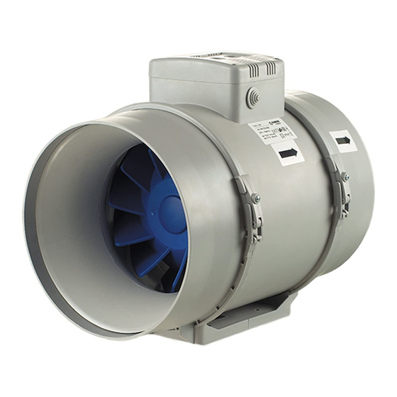
- Page 1 INLINE MIXED-FLOW FANS Turbo USER’S MANUAL...
-
Page 2: Table Of Contents
CONTENTS Delivery set ..........................................7 Brief description ........................................7 Operation guidelines ......................................8 Designation key ........................................9 Mounting ..........................................10 Control logic ..........................................11 Technical maintenance ......................................13 Troubleshooting ........................................13 Storage and transportation regulations ..............................14 Manufacturer’s warranty ....................................15 This user’s manual is a main operating document intended for technical, maintenance, and operating staff. The manual contains information about purpose, technical details, operating principle, design, and installation of the Turbo unit and all its modifications. - Page 3 All user’s manual requirements as well as the provisions of all the applicable local and national construction, electrical, and technical norms and standards must be observed when installing and operating the unit. Disconnect the unit from the power supply prior to any connection, servicing, maintenance, and repair operations.
- Page 4 Do not expose the unit to adverse atmospheric agents (rain, sun, etc.). Transported air must not contain any dust or other solid impurities, sticky substances, or fibrous materials. Do not use the unit in a hazardous or explosive environment containing spirits, gasoline, insecticides, etc. Do not close or block the intake or extract vents in order to ensure the efficient air flow.
- Page 5 This appliance can be used by children aged from 8 years and above and persons with reduced physical, sensory or mental capabilities or lack of experience and knowledge if they have been given supervision or instruction concerning use of the appliance in a safe way and understand the hazards involved.
- Page 6 CAUTION: In order to avoid a safety hazard due to inadvertent resetting of the thermal cut-out, this unit must not be supplied through an external switching device, such as a timer, or connected to a circuit that is regularly switched on and off by the utility. Ensure that the unit is switched off from the supply mains before removing the guard.
-
Page 7: Delivery Set
The fan is designed for connection to ø 100, 125, 150, 160, 200, 250 and 315 mm air ducts. The unit is equipped with a two speed motor. Ø D 195,8 241/255* 302,5 Turbo 100 195,6 241/255* 258,5 Turbo 125 220,1 251/265* Turbo 150 220,1 251/265* Turbo 160 261/278* 295,5 Turbo 200... -
Page 8: Operation Guidelines
OPERATION GUIDELINES The fan is rated for connection to single-phase AC 220-240 V/50 Hz or 220 V/60 Hz power mains. The unit is rated for continuous operation. The arrow on the fan casing must match the air direction in the system. Ingress protection rating against access to hazardous parts and water ingress is IPX4. -
Page 9: Designation Key
DESIGNATION KEY Turbo Options: T: timer W1: power cord with a plug US: speed switch Gl1: speed controller with an electronic thermostat and a temperature sensor integrated inside an air duct. Temperature-based operation logic G1: speed controller with an electronic thermostat and an outdoor temperature sensor fixed on a 4 m cord. -
Page 10: Mounting
MOUNTING The fan is suitable both for horizontal or vertical mounting on the floor, on the wall or on the ceiling (Fig. 1). The fan can be installed independently or as part of a set with parallel or in-series connection (Fig. 2). Install minimum 1 m long air duct on the intake spigot side in case of horizontal fan mounting or a hood in case of vertical fan mounting. -
Page 11: Control Logic
CONTROL LOGIC It is possible to control the fan rotation speed without options by voltage, as well as by thyristor controllers. The speed controller is purchased separately. Warning! When adjusting the voltage, make sure there is no unusual noise or vibration at reduced motor speed. The motor current may exceed the rated current during voltage regulation. - Page 12 The Turbo Gl1/GTl1/GSl1/GS1 fan is equipped with an electronic TSC control unit (speed controller with electronic thermostat) for automatic speed control (air flow control) depending on the air temperature (Fig. 22). The terminal box cover incorporates 2 control knobs: • for setting the fan speed;...
-
Page 13: Technical Maintenance
TECHNICAL MAINTENANCE The fan surfaces must be regularly cleaned (once in 6 months) from dirt and dust (Fig. 24-30). Disconnect the fan from power mains prior to any maintenance operations. To clean the fan, use a soft cloth or a brush wetted in a mild detergent solution. -
Page 14: Storage And Transportation Regulations
STORAGE AND TRANSPORTATION REGULATIONS • Store the unit in the manufacturer’s original packaging box in a dry closed ventilated premise with temperature range от +5 ˚С до +40 ˚С and relative humidity up to 70 %. • Storage environment must not contain aggressive vapors and chemical mixtures provoking corrosion, insulation, and sealing deformation. -
Page 15: Manufacturer's Warranty
MANUFACTURER’S WARRANTY Blauberg Warranty: • This warranty is given by Blauberg Australasia Pty Ltd, with an office at Unit 5, 45A Eastern Creek Drive, Eastern Creek, New South Wales 2766, Australia. Phone 1300 475-504. • From the date of purchase, the original purchaser is entitled to free replacement parts, or a new unit for a period of 24 месяцев... - Page 16 FOLLOWING THE REGULATIONS STIPULATED HEREIN WILL ENSURE A LONG AND TROUBLE-FREE OPERATION OF THE UNIT. USER’S WARRANTY CLAIMS SHALL BE SUBJECT TO REVIEW ONLY UPON PRESENTATION OF THE UNIT, THE PAYMENT DOCUMENT AND THE USER’S MANUAL WITH THE PURCHASE DATE STAMP.
- Page 17 min 1 m...
- Page 20 Turbo MAX / MIN...
- Page 21 Turbo T MAX / MIN MAX / MIN Terminal block for 4 contacts Terminal block for 5 contacts...
- Page 23 STOP...
- Page 24 Speed control knob Turbo Gl1/GTl1/GSl1 Turbo G1/GT1/GS1 Thermostat control knob Turbo FR1 Speed control knob...
- Page 27 Quality Inspector’s Stamp Sold by (name and stamp of the seller) Manufacture Date Purchase Date...
- Page 28 Turbo________________________ www.blaubergventilatoren.de Blauberg_Australasia_B77EN-05...
Need help?
Do you have a question about the Turbo 125 and is the answer not in the manual?
Questions and answers