Table of Contents
Advertisement
Quick Links
Advertisement
Table of Contents

Related Manuals for BLAUBERG Ventilatoren TUBO


Summary of Contents for BLAUBERG Ventilatoren TUBO
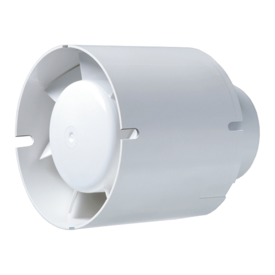
- Page 1 AXIAL FAN TUBO TUBO-C User’s manual...
-
Page 2: Table Of Contents
Manufacturer’s warranty ..........................................13 This user’s manual is a main operating document intended for technical, maintenance, and operating staff. The manual contains information about purpose, technical details, operating principle, design, and installation of the Tubo unit and all its modifications. - Page 3 READ THE USER’S MANUAL CAREFULLY BEFORE PROCEEDING WITH INSTALLATION WORKS. COMPLIANCE WITH THE MANUAL REQUIREMENTS ENSURES RELIABLE OPERATION AND LONG SERVICE LIFE OF THE UNIT. KEEP THE USER’S MANUAL AVAILABLE AS LONG AS YOU USE THE UNIT. YOU MAY NEED TO REREAD THE INFORMATION ON THE PRODUCT SERVICING.
- Page 4 • Fixed electrical wiring must be equipped with an automatic circuit breaker. • The unit must be connected to power mains through a double pole circuit breaker integrated into the fixed wiring system with opening of contacts at all poles. The gap between the circuit breaker contacts at all poles must be not less than 3 mm.
- Page 5 other fire-protection devices. Sufficient air supply must be provided for proper combustion and exhaust of gases through the chimney of fuel burning equipment to prevent back drafting. • Transported air must not contain any dust or other solid impurities, sticky substances, or fibrous materials. •...
- Page 6 document’s preparation. • The Company reserves the right to modify the technical characteristics, design, or configuration of its products at any time in order to incorporate the latest technological developments. • No part of this publication may be reproduced, stored in a retrieval system, or transmitted, in any form or by any means in any information search system or translated into any language in any form without the prior written permission of the Company.
-
Page 7: Delivery Set
Screws with dowels (only for the models with a mounting bracket) – 4 pcs. Plastic screwdriver (only for the models with a timer) – 1 pc. Seal ring (only for the Tubo model) – 2 pcs. User’s manual – 1 pc. -
Page 8: Designation Key
DESIGNATION KEY Tubo -X Voltage: motor with 12 V/50 Hz rated voltage Variations of the base model: e: slide bearing, without backdraft damper Basic options T: turn-off delay timer Outlet spigot diameter [mm] 100/125/150 Motor modification Max: high-powered motor Still: low-noise motor... -
Page 9: Installation
INSTALLATION The fan can be installed vertically or horizontally in a round duct (Fig. 2) of appropriate diameter (Fig. 1). Fan installation sequence: • Disconnect power supply (Fig. 3). • Mark and drill holes for fastening the mounting bracket of the fan and then install the fan (Fig. 4-6). •... -
Page 10: Electronics Operation Algorithm
ELECTRONICS OPERATION ALGORITHM The fan with the T timer activates upon control voltage application to the LT input terminal by the S external switch (e.g. indoor light switch). After the control voltage is off, the fan continues to operate within the time set by the timer ranging from 2 to 30 minutes. -
Page 11: Technical Maintenance
TECHNICAL MAINTENANCE The fan maintenance periodicity is at least once per 6 months. Maintenance steps: • Connect power supply to the fan (Fig. 13). • Remove the air ducts (Fig. 14). • To clean the fan, use a soft cloth and a brush wetted in a mild detergent solution. •... -
Page 12: Storage And Transportation Regulations
STORAGE AND TRANSPORTATION REGULATIONS • Store the unit in the manufacturer’s original packaging box in a dry closed ventilated premise with temperature range from +5 °C to +40 °C and relative humidity up to 70 %. • Storage environment must not contain aggressive vapors and chemical mixtures provoking corrosion, insulation, and sealing deformation. -
Page 13: Manufacturer's Warranty
MANUFACTURER’S WARRANTY The product is in compliance with EU norms and standards on low voltage guidelines and electromagnetic compatibility. We hereby declare that the product complies with the provisions of Electromagnetic Compatibility (EMC) Directive 2014/30/ EU of the European Parliament and of the Council, Low Voltage Directive (LVD) 2014/35/EU of the European Parliament and of the Council and CE-marking Council Directive 93/68/EEC. - Page 14 components caused by the user. • Redesign or engineering changes to the unit. • Replacement and use of any assemblies, parts and components not approved by the manufacturer. • Unit misuse. • Violation of the unit installation regulations by the user. •...
- Page 15 D [mm] d [mm] B [mm] b [mm] Tubo-C 100 Tubo 100 Tubo-C 125 Tubo 125 ø D ø d Tubo-C 150 Tubo 150...
- Page 17 Tubo/Tubo-C 100/125/150 Tubo 100/125/150 T N(~*) N(~*) L(~*) L(~*) N(~*) L(~*)
- Page 23 Quality Inspector’s Stamp Sold by (name and stamp of the seller) Manufacture Date Purchase Date...
- Page 24 Tubo Still Tubo-C Plus www.blaubergventilatoren.de B214EN-01...
Need help?
Do you have a question about the TUBO and is the answer not in the manual?
Questions and answers