Table of Contents
Advertisement
Quick Links
Advertisement
Table of Contents

Subscribe to Our Youtube Channel
Related Manuals for BLAUBERG Ventilatoren Sileo Series


Summary of Contents for BLAUBERG Ventilatoren Sileo Series
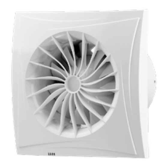
- Page 1 AXIAL FAN Sileo Sileo Design User’s manual...
-
Page 2: Table Of Contents
CONTENTS Delivery set ................................................7 Brief description ..............................................7 Operation guidelines ............................................7 Designation key ..............................................8 Installation................................................9 Fan operation setup ............................................10 Technical maintenance ........................................... 11 Troubleshooting ..............................................11 Storage and transportation regulations ....................................12 Manufacturer’s warranty ..........................................13 This user’s manual is a main operating document intended for technical, maintenance, and operating staff. - Page 3 This unit is not intended for use by persons (including children) with reduced physical, sensory or mental capabilities, or lack of experience and knowledge, unless they have been given supervision or instruction concerning use of the unit by a person responsible for their safety.
- Page 4 Precautions must be taken to avoid the back-flow of gases into the room from the open flue of gas or other fuel-burning appliances. Connection to the mains must be made through a disconnecting device, which is integrated into the fixed wiring system in accordance with the wiring rules for design of electrical units, and has a contact separation in all poles that allows for full disconnection under overvoltage category III conditions.
- Page 5 All user’s manual requirements as well as the provisions of all the applicable local and national construction, electrical, and technical norms and standards must be observed when installing and operating the unit. Disconnect the unit from the power supply prior to any connection, servicing, maintenance, and repair operations.
- Page 6 Transported air must not contain any dust or other solid impurities, sticky substances, or fibrous materials. Do not use the unit in a hazardous or explosive environment containing spirits, gasoline, insecticides, etc. Do not close or block the intake or extract vents in order to ensure the efficient air flow.
-
Page 7: Delivery Set
DELIVERY SET Fan — 1 pc. Screws and dowels — 4 pcs. Plastic screwdriver (only for models with a timer) — 1 pc. User’s manual — 1 pc. Packing box — 1 pc. Sealing gasket — 1 pc. BRIEF DESCRIPTION The product is an axial fan for exhaust ventilation of small and medium-sized premises. -
Page 8: Designation Key
DESIGNATION KEY Sileo V2 100 Т 220 V/60 Hz Mains parameters _: 220-240 V/50 Hz 220 V/60 Hz: supply voltage 220 V, power frequency 60 Hz 12: supply voltage 12 V, power frequency 50 Hz Additional options S: pull cord switch Т: turn-off delay timer ТR: turn-on and turn-off delay timer SТ: pull cord switch and turn-off delay timer... -
Page 9: Installation
INSTALLATION The fan is designed for wall or ceiling mounting with direct air discharge to the ventilation shaft or into the round air duct of matching diameter (Fig. 2). Fan installation with direct air discharge upwards is not allowed (Fig. 2). Fan installation sequence: Step 1. -
Page 10: Fan Operation Setup
FAN OPERATION SETUP THE TIMER BOARD IS UNDER MAINS VOLTAGE. MAKE SURE THE FAN IS COMPLETELY DISCONNECTED FROM THE POWER MAINS BEFORE ADJUSTING i — interval timer turning on and adjustment is performed with the potentiometer T . To turn the interval timer off, set the potentiometer Ti into the leftmost position. -
Page 11: Technical Maintenance
TECHNICAL MAINTENANCE The fan maintenance periodicity is at least once per 6 months. Maintenance steps: • Disconnect the fan from power supply and make sure electricity has been turned off (Fig. 21). • Remove the front panel, wipe the fan with a dry cloth or a brush (Fig. 22). •... -
Page 12: Storage And Transportation Regulations
STORAGE AND TRANSPORTATION REGULATIONS • Store the unit in the manufacturer’s original packaging box in a dry closed ventilated premise with temperature range from +5 °C to + 40 °C and relative humidity up to 70 %. • Storage environment must not contain aggressive vapors and chemical mixtures provoking corrosion, insulation, and sealing deformation. -
Page 13: Manufacturer's Warranty
MANUFACTURER’S WARRANTY The product is in compliance with EU norms and standards on low voltage guidelines and electromagnetic compatibility. We hereby declare that the product complies with the provisions of Electromagnetic Compatibility (EMC) Directive 2014/30/ EU of the European Parliament and of the Council, Low Voltage Directive (LVD) 2014/35/EU of the European Parliament and of the Council and CE-marking Council Directive 93/68/EEC. - Page 14 • Replacement and use of any assemblies, parts and components not approved by the manufacturer. • Unit misuse. • Violation of the unit installation regulations by the user. • Violation of the unit control regulations by the user. • Unit connection to power mains with a voltage different from the one stated in the user's manual. •...
- Page 15 Dimensions [mm] Ø D Sileo 100 Sileo 125 Sileo Design 100...
- Page 16 Latches...
- Page 17 ...100/125 ...100/125 Fan does not run. L(2) N(3) S switch to ON or pull cord switch L(2) N(3) Fan runs ...100/125 S S switch to OFF or pull cord switch L(2) N(3)
- Page 18 ... 100/125 T/TR LT(1) Fan does not run. Fan does not run. L(2) N(3) S switch to ON S switch to ON LT(1) or pull cord switch or pull cord switch L(2) N(3) Activation of turn-on Fan runs delay timer (0-2 minutes) ...
- Page 19 ... 100/125 H LT(1) Fan does not run L(2) N(3) S switch to ON or pull cord switch LT(1) Humidity exceeds L(2) set point N(3) Fan runs ... 100/125 SH S switch to OFF or pull cord switch L(2) Fan runs N(3) Humidity is Humidity exceeds...
- Page 20 ... 100/125 IR LT(1) Fan does not run L(2) N(3) Motion detected Fan runs No motion detected Activation of turn-off delay timer (2-30 minutes)
- Page 21 ... V2 100/125 ... V2 100/125 (speed 1) LT(1) Fan does not run. L(2) N(3) S switch to ON or pull cord switch LT(1) L(2) N(3) Fan runs at speed 1 ... V2 100/125 S (speed 1) S switch to OFF or pull cord switch LT(1) L(2)
- Page 22 ... V2 100/125 (speed 1 and 2) speed 1 and 2 speed LT(1) Fan does not run L(2) N(3) S switch to ON speed LT(1) or pull cord switch L(2) N(3) ... V2 100/125 S (speed 1 and 2) LT(1) L(2) Speed switch speed...
- Page 23 ... V2 100/125 LT(1) LT(1) L(2) L(2) N(3) N(3) Off 6/12/24 hours Interval timer The fan does not run Fan runs at speed 1 Contact of the S switch Contact of the S switch Start of interval or the pull cord switch is or the pull cord switch is timer (6, 12 or 24 hours) CLOSED...
- Page 24 ... V2 100/125 H LT(1) Fan runs at speed 1 L(2) N(3) Contact of the S switch or the pull cord switch is CLOSED LT(1) Humidity exceeds set point Activation of turn-on L(2) delay timer (60 seconds) N(3) Activation of turn-on delay timer (60 seconds) The contact of the S switch or the pull cord switch is...
- Page 25 Latches...
- Page 27 Quality Inspector’s Stamp Sold by (name and stamp of the seller) Manufacture Date Purchase Date...
- Page 28 Sileo __________________________________________________________ www.ventilation-system.com B235-1EN-01...
Need help?
Do you have a question about the Sileo Series and is the answer not in the manual?
Questions and answers