Advertisement
Advertisement

Related Manuals for BLAUBERG Ventilatoren Turbo 100


Summary of Contents for BLAUBERG Ventilatoren Turbo 100
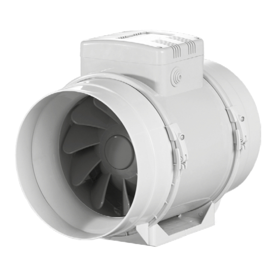
- Page 1 INLINE MIXED-FLOW FANS Turbo USER’S MANUAL...
-
Page 2: Table Of Contents
CONTENTS Delivery set ..........................................6 Brief description ........................................6 Operation guidelines ......................................7 Designation key ........................................8 Installation ..........................................9 Electronics operation algorithm ..................................10 Technical maintenance ......................................12 Storage and transportation regulations ..............................12 Manufacturer’s warranty ....................................13 This user’s manual is a main operating document intended for technical, maintenance, and operating staff. The manual contains information about purpose, technical details, operating principle, design, and installation of the Turbo unit and all its modifications. - Page 3 All user’s manual requirements as well as the provisions of all the applicable local and national construction, electrical, and technical norms and standards must be observed when installing and operating the unit. Disconnect the unit from the power supply prior to any connection, servicing, maintenance, and repair operations.
- Page 4 • Do not expose the device to adverse atmospheric agents (rain, sun, etc.). • Transported air must not contain any dust or other solid impurities, sticky substances, or fibrous materials. • Do not use the unit in a hazardous or explosive environment containing spirits, gasoline, insecticides, etc.
- Page 5 This appliance is not intended for use by persons (including children) with reduced physical, sensory or mental capabilities, or lack of experience and knowledge, unless they have been given supervision or instruction concerning use of the appliance by a person responsible for their safety.
- Page 6 If the supply cord is damaged, it must be replaced by the manufacturer, its service agent, or similarly qualified persons in order to avoid a safety hazard. If the cord set is damaged, it must be replaced by a special cord set available from the manufacturer or its service agent.
-
Page 7: Delivery Set
The fan is designed for connection to ø 100, 125, 150, 160, 200, 250 and 315 mm air ducts. The unit is equipped with a two speed motor. Ø D 195,8 241/255* 302,5 Turbo 100 195,6 241/255* 258,5 Turbo 125 220,1... -
Page 8: Operation Guidelines
OPERATION GUIDELINES The fan is rated for connection to single-phase AC 220-240 V/50 Hz or 220 V/60 Hz power mains. The unit is rated for continuous operation. The arrow on the fan casing must match the air direction in the system. Ingress protection rating against access to hazardous parts and water ingress is IPX4. -
Page 9: Designation Key
DESIGNATION KEY Turbo Options: T: timer R: power cord with a plug V: speed switch U: speed controller with an electronic thermostat and a temperature sensor integrated inside an air duct. Temperature-based operation logic Un: speed controller with an electronic thermostat and an outdoor temperature sensor fixed on a 4 m cord. - Page 10 MOUNTING The fan is suitable both for horizontal or vertical mounting on the floor, on the wall or on the ceiling (Fig. 1). The fan can be installed independently or as part of a set with parallel or in-series connection (Fig. 2). Install minimum 1 m long air duct on the intake spigot side in case of horizontal fan mounting or a hood in case of vertical fan mounting.
- Page 11 CONTROL LOGIC It is possible to control the fan rotation speed without options by voltage, as well as by thyristor controllers. The speed controller is purchased separately. Warning! When adjusting the voltage, make sure there is no unusual noise or vibration at reduced motor speed. The motor current may exceed the rated current during voltage regulation.
- Page 12 The Turbo XXX Gl1/GTl1/GSl1/GS1 fan is equipped with an electronic TSC control unit (speed controller with electronic thermostat) for automatic speed control (air flow control) depending on the air temperature (Fig. 22). The terminal box cover incorporates 2 control knobs: •...
-
Page 13: Technical Maintenance
The Turbo XXX FR1 fan is equipped with a speed controller that enables switching the fan on/off, smooth speed (air flow) control from minimum to maximum value (Fig. 22). TECHNICAL MAINTENANCE The fan surfaces must be regularly cleaned (once in 6 months) from dirt and dust (Fig. 24-30). Disconnect the fan from power mains prior to any maintenance operations. -
Page 14: Storage And Transportation Regulations
STORAGE AND TRANSPORTATION REGULATIONS • Store the unit in the manufacturer’s original packaging box in a dry closed ventilated premise with temperature range от +5 ˚С до +40 ˚С and relative humidity up to 70 %. • Storage environment must not contain aggressive vapors and chemical mixtures provoking corrosion, insulation, and sealing deformation. -
Page 15: Manufacturer's Warranty
MANUFACTURER’S WARRANTY The product is in compliance with EU norms and standards on low voltage guidelines and electromagnetic compatibility. We hereby declare that the product complies with the provisions of Electromagnetic Compatibility (EMC) Directive 2014/30/EU of the European Parliament and of the Council, Low Voltage Directive (LVD) 2014/35/EU of the European Parliament and of the Council and CE-marking Council Directive 93/68/EEC. - Page 16 • User’s failure to ensure timely technical maintenance of the unit. • External damage to the unit casing (excluding external modifications as required for installation) and internal components caused by the user. • Redesign or engineering changes to the unit. •...
- Page 17 min 1 m...
- Page 20 Turbo XXX MAX / MIN...
- Page 21 Turbo XXX T MAX / MIN MAX / MIN TERMINAL BLOCK FOR 4 CONTACTS TERMINAL BLOCK FOR 5 CONTACTS...
- Page 23 STOP...
- Page 24 Speed control knob Turbo G1/GT1/GS1 Turbo Gl1/GTl1/GSl1 Thermostat control knob Turbo FR1 Speed control knob...
- Page 27 Quality Inspector’s Stamp Sold by (name and stamp of the seller) Manufacture Date Purchase Date...
- Page 28 Turbo________________________ www.blaubergventilatoren.de B77EN-05...
Need help?
Do you have a question about the Turbo 100 and is the answer not in the manual?
Questions and answers