Table of Contents
Advertisement
Quick Links
Advertisement
Table of Contents

Related Manuals for BLAUBERG Ventilatoren Turbo EC


Summary of Contents for BLAUBERG Ventilatoren Turbo EC
- Page 1 INLINE MIXED-FLOW FANS Turbo EC USER’S MANUAL...
-
Page 2: Table Of Contents
This user’s manual is a main operating document intended for technical, maintenance, and operating staff. The manual contains information about purpose, technical details, operating principle, design, and installation of the Turbo EC unit and all its modifications. Technical and maintenance staff must have theoretical and practical training in the field of ventilation systems and should be able to work in accordance with workplace safety rules as well as construction norms and standards applicable in the territory of the country. - Page 3 This unit is not intended for use by persons (including children) with reduced physical, sensory or mental capabilities, or lack of experience and knowledge, unless they have been given supervision or instruction concerning use of the unit by a person responsible for their safety.
- Page 4 with the wiring rules for design of electrical units, and has a contact separation in all poles that allows for full disconnection under overvoltage category III conditions. If the supply cord is damaged, it must be replaced by the manufacturer, its service agent, or similarly qualified persons in order to avoid a safety hazard.
- Page 5 in carbon monoxide poisoning. After installation of the unit the operation of flued gas appliances should be tested by a competent person to ensure that back flow of combustion gases does not occur. All operations described in this manual must be performed by qualified personnel only, properly trained and qualified to install, make electrical connections and maintain ventilation units.
- Page 6 Only qualified electricians with a work permit for electrical units up to 1000 V are allowed for installation. The present user’s manual should be carefully read before beginning works. Check the unit for any visible damage of the impeller, the casing, and the grille before starting installation.
- Page 7 Do not sit on the unit and do not put objects on it. The information in this user’s manual was correct at the time of the document’s preparation. The Company reserves the right to modify the technical characteristics, design, or configuration of its products at any time in order to incorporate the latest technological developments.
-
Page 8: Delivery Set
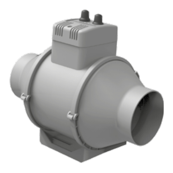
DELIVERY SET — 1 pc. Screws and dowels — 4 pcs. User’s manual — 1 pc. Packing box — 1 pc. BRIEF DESCRIPTION The product described herein is a mixed-flow inline fan for supply or exhaust ventilation of premises heated during winter time. -
Page 9: Designation Key
DESIGNATION KEY Turbo Options: Gl1: speed controller with an electronic thermostat and a temperature sensor integrated inside an air duct. Temperature- based operation logic G1: speed controller with an electronic thermostat and an outdoor temperature sensor fixed on a 4 m cable. Temperature- based operation logic FR1: integrated smooth speed controller Spigot diameter [mm]... -
Page 10: Installation
INSTALLATION The fan is suitable both for horizontal or vertical mounting on the floor, on the wall or on the ceiling (Fig. 1). While mounting the fan provide extra protection against water ingress, such as: 1. For the top mounting: install an outer protecting hood above (Fig. 2). 2. -
Page 11: Operation Algorithm
- DIP switch in EXT position. The control signal is set by the S1 external control unit. The Turbo EC G1/Gl1 fan is equipped with an electronic module TSC (speed controller with an electronic thermostat) for automatic fan speed control (air flow) depending on the air temperature. -
Page 12: Maintenance
MAINTENANCE Clean the product surfaces regularly (once in 6 months) from dust and dirt (Fig. 18-21). Disconnect the fan from power mains prior to any maintenance operations. To clean the fan, use a soft cloth or a brush wetted in a mild detergent solution. -
Page 13: Storage And Transportation Regulations
STORAGE AND TRANSPORTATION REGULATIONS • Store the unit in the manufacturer’s original packaging box in a dry closed ventilated premise with temperature range from +5 ˚C to +40 ˚C and relative humidity up to 70 %. • Storage environment must not contain aggressive vapors and chemical mixtures provoking corrosion, insulation, and sealing deformation. -
Page 14: Manufacturer's Warranty
MANUFACTURER’S WARRANTY Blauberg Warranty: • This warranty is given by Blauberg Australasia Pty Ltd, with an office at Unit 5, 45A Eastern Creek Drive, Eastern Creek, New South Wales 2766, Australia. Phone 1300 475-504. • From the date of purchase, the original purchaser is entitled to free replacement parts, or a new unit for a period of 24 months years from the date of purchase. - Page 15 Eastern Creek Drive, Eastern Creek, New South Wales 2766, as set out in the instruction manual in the box. If your product does not provide the general features and functions described in the user documentation in the five year period after delivery to you, please call Blauberg Australasia Pty Ltd, ABN 85 637 003 582 on 1300 475-504 with details of your product, serial number and proof of purchase.
- Page 16 1 ØD 1 ØD 3 ØD 3 ØD...
- Page 19 230 V External 50/60 Hz control device...
- Page 20 Speed control knob Turbo EC G1 Turbo EC Gl1 Thermostat control knob Turbo EC FR1 Speed control knob...
- Page 23 Quality Inspector’s Stamp Sold by (name and stamp of the seller) Manufacture Date Purchase Date...
- Page 24 www.blaubergventilatoren.de B_Australasia77-1EN-05...
Need help?
Do you have a question about the Turbo EC and is the answer not in the manual?
Questions and answers