Sign In
Upload
Download
Table of Contents
Contents
Add to my manuals
Delete from my manuals
Share
URL of this page:
HTML Link:
Bookmark this page
Add
Manual will be automatically added to "My Manuals"
Print this page
×
Bookmark added
×
Added to my manuals
Manuals
Brands
Image Manuals
Dryer
DE 30
Instruction manual
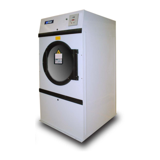
Image DE 30 Instruction Manual
Tumble dryer
Hide thumbs
1
Table Of Contents
2
3
4
5
6
7
8
9
10
11
12
13
14
15
16
17
18
19
20
21
22
23
24
25
26
27
28
29
30
31
32
33
34
35
36
37
38
39
40
41
42
43
44
45
46
47
48
49
50
51
52
53
54
55
56
57
58
59
60
61
62
63
64
65
66
67
68
69
70
71
page
of
71
Go
/
71
Contents
Table of Contents
Troubleshooting
Bookmarks
Table of Contents
Table of Contents
Section 1: Important Information
Receiving and Handling
Safety Precautions
Section 2: Specifications / Component Identification
Technical Specifications
Technical Dimension
Component Identification
Section 3: Installation Procedures
Location Requirements
Unpackg / Setting up
Dryer Enclosue Requirements
Frsh Air Supply
Exhaust Requirements
Electrical Inforrmation
Gas Information
Steam Information
Preparation for Opertion / Start up
Pre-Operational Tests
Section 4: Operating and Programming Instructions
Operating Instructions
Setting the Program
Setting the Controller
Meaning of the Alarm Massages
Section 5: Warranty Information
Warranty
Returning Warranty Part(S)
Section 6: Routine Maintenance
Cleaning
Adjustments
Lubrication
Section 7: Trouble Shooting
Microprocessor Models
Timer Models
Advertisement
Quick Links
1
Table of Contents
2
Technical Specifications
3
Electrical Inforrmation
4
Setting the Program
5
Meaning of the Alarm Massages
6
Section 7: Trouble Shooting
Download this manual
Table of
Contents
Previous
Page
Next
Page
1
2
3
4
5
Advertisement
Table of Contents
Need help?
Do you have a question about the DE 30 and is the answer not in the manual?
Ask a question
Questions and answers
Related Manuals for Image DE 30
Dryer Image DE 50 Instruction Manual
Tumble dryer (71 pages)
Dryer Image DE 75 Instruction Manual
Tumble dryer (71 pages)
Dryer Image DE100 Instruction Manual
(74 pages)
This manual is also suitable for:
De 50
De 75
Table of Contents
Print
Rename the bookmark
Delete bookmark?
Delete from my manuals?
Login
Sign In
OR
Sign in with Facebook
Sign in with Google
Upload manual
Upload from disk
Upload from URL


Need help?
Do you have a question about the DE 30 and is the answer not in the manual?
Questions and answers