Table of Contents
Advertisement
Quick Links
Advertisement
Chapters
Table of Contents

Related Manuals for Beckhoff CP6700-0001


Summary of Contents for Beckhoff CP6700-0001
- Page 1 Manual | EN CP6700-0001 2024-03-12 | Version: 2.0...
-
Page 3: Table Of Contents
Grounding the panel PC.................... 24 4.3.2 Connecting cables and power supply ................ 25 Switching the panel PC on and off .................... 26 5 Beckhoff Device Manager ........................ 27 6 Decommissioning ........................... 29 Disconnecting the power supply and cables ................... 29 Disassembly and disposal....................... 30 7 Maintenance ............................ 31... - Page 4 Table of contents Version: 2.0 CP6700-0001...
-
Page 5: Notes On The Documentation
Copyright © Beckhoff Automation GmbH & Co. KG. Publication of this document on websites other than ours is prohibited. Offenders will be held liable for the payment of damages. All rights reserved in the event of the grant of a patent, utility model or design. -
Page 6: For Your Safety
Exclusion of liability Beckhoff shall not be liable in the event of non-compliance with this documentation and thus the use of the devices outside the documented operating conditions. -
Page 7: Fundamental Safety Instructions
• the operating instructions are in good condition and complete, and always available for reference at the location where the products are used. CP6700-0001 Version: 2.0... -
Page 8: Notes On Information Security
For your safety Notes on information security The products of Beckhoff Automation GmbH & Co. KG (Beckhoff), insofar as they can be accessed online, are equipped with security functions that support the secure operation of plants, systems, machines and networks. Despite the security functions, the creation, implementation and constant updating of a holistic security concept for the operation are necessary to protect the respective plant, system, machine and networks against cyber threats. -
Page 9: Product Overview
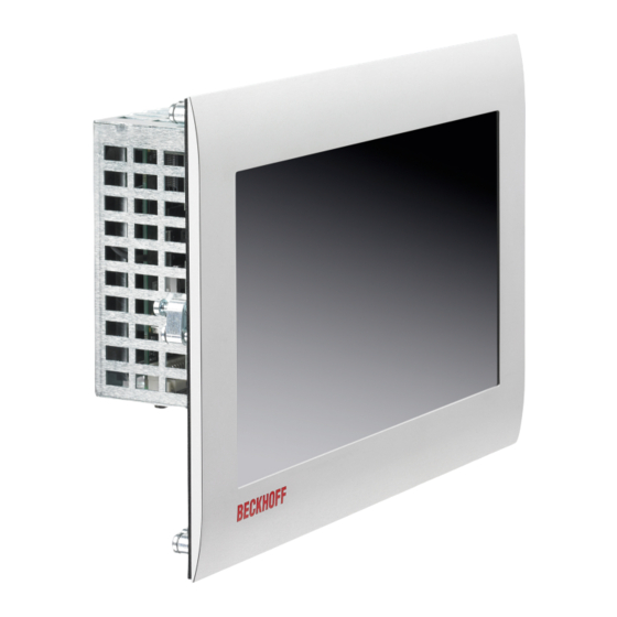
For explanations of the push button extensions and the functions, refer to the manual C9900-G072/G073. Figure 1 shows an example of the panel PC without (1) and with (2) push button extension. Fig. 1: Panel PC with and without push button extension CP6700-0001 Version: 2.0... -
Page 10: Structure
Name plate Information on the equipment of the panel PC Clamping lever Mounting the panel PC in the control cabinet wall Access to interfaces Interfaces on the underside Display and touch screen glass Operation of the panel PC Version: 2.0 CP6700-0001... -
Page 11: Interface Description
The plug is included in the delivery. You can obtain a replacement plug from your Beckhoff Sales using the following ordering option: • C9900-P943: Power supply connector for Industrial PC C60xx, C6905, CP6700 and CP6706 CP6700-0001 Version: 2.0... -
Page 12: Ethernet Rj45
The RJ45 connection technology with twisted-pair cables is used. The maximum length of the cable connection is 100 m. The controllers are used as follows, based on the device generation: Table 3: Controller classification based on device generation Device generation Controller Mbit/s ® CP6700-0001-0050 Intel i210 (MAC/PHY) 100/1000 ® CP6700-0001-0060 Intel i210 (MAC/PHY) 100/1000 ®... -
Page 13: Usb
The industrial PC has four USB interfaces (X105-X108). They are used to connect peripheral devices with USB interfaces. The following table shows the interface assignment based on the device generation: Table 7: USB interface device generation Device generation USB interface CP6700-0001-0050 4x USB 2.0 (X105-X108) CP6700-0001-0060 2x USB 3.0 (X107, X108) 2x USB 2.0 (X105, X106) CP6700-0001-0070 2x USB 3.1 Gen. -
Page 14: Dvi
DDC Clock + 5 V Power TMDS Clock Shield DDC Data Ground (+ 5 V, Analog H/ TMDS Clock + V Sync) Analog Vertical Sync Hot Plug Detect TMDA Clock - Version: 2.0 CP6700-0001... -
Page 15: Status Leds
TwinCAT Config (fieldbus error) Green Steadily lit TwinCAT Run Green/red Flashing TwinCAT Run (fieldbus error) HDD LED Color Flashing interval Meaning Steadily lit Access to storage medium PWR LED Color Flashing interval Meaning Green Steadily lit PC on PC off CP6700-0001 Version: 2.0... -
Page 16: Name Plate
MAC addresses of the Ethernet interfaces (X103, X104) PE protective conductor connection for low-resistance protective earthing and functional earthing of the panel PC Status LEDs Power supply connection (X101) Battery position Ethernet interfaces (X103, X104) Storage medium position USB interfaces (X105-X108) DVI interface (X109) Version: 2.0 CP6700-0001... - Page 17 Note: Here are the symbols applicable to the device such as Ce, EAC, UKCA, . The approvals of your device can be found on the name plate and in chapter 10.2 Approvals. Address of the vendor FCC approval Variant number: commercial number of the order code including ordering options CP6700-0001 Version: 2.0...
-
Page 18: Commissioning
You can either order a Beckhoff protective film individually and fit it yourself retrospectively, or you can order the film for fitting directly ex factory. Please refer to the price list for the available protective films according to the display size of your device. -
Page 19: Transport And Unpacking
4. Check your delivery for completeness by comparing it with your order. 5. Check the contents for visible shipping damage. In case of discrepancies between the package contents and the order, or in case of transport damage, please inform Beckhoff Service (see Chapter 10.1 Service and Support [} 39]). CP6700-0001 Version: 2.0... -
Page 20: Control Cabinet Installation
PC in the control cabinet front. All dimensions are in mm. Figure 10 shows the dimensions of the panel PC without push button extension. 57,5 Fig. 10: Dimensions Figure 11 shows the dimensions of the panel PC with push button extension. Version: 2.0 CP6700-0001... -
Page 21: Fig. 11 Dimensions Push Button Extension
To install and secure the control panel in the control cabinet, follow the steps shown in Fig. 13 and 14: 1. Insert the control panel at the intended position in the control cabinet wall. Make sure that the device is secured against falling out until it is fastened properly. CP6700-0001 Version: 2.0... -
Page 22: Fig. 13 Wall Positioning
2. Turn the clamping levers 90° outwards (sections A and B). 3. Tighten the clamping levers with the Allen key 2.5 mm (section C). ð You have mounted the control panel in the control cabinet. Fig. 14: Control cabinet installation Version: 2.0 CP6700-0001... -
Page 23: Connecting The Panel Pc
Peripheral devices connected to the device with their own power supply must have the same potential for the PE and "0 V" conductors as the control panel (no potential difference). CP6700-0001 Version: 2.0... -
Page 24: Grounding The Panel Pc
The functional earth is necessary for the EMC of the device. The functional earth is also established via the protective conductor connection PE on the rear of the housing (see Fig. 15). Use cables with a minimum cross-section of 4 mm for the ground connection. Version: 2.0 CP6700-0001... -
Page 25: Connecting Cables And Power Supply
1. Plug the voltage connector into the voltage socket on the device. 2. Screw the voltage connector to the voltage socket. 3. Connect the device to your external 24 V power supply. 4. Switch on the 24 V power supply. ð You have connected the power supply. CP6700-0001 Version: 2.0... -
Page 26: Switching The Panel Pc On And Off
When you switch on the PC for the first time, the optionally pre-installed operating system will be started. For any additional hardware you have connected, you have to install the drivers yourself afterwards. In addition, the Beckhoff Device Manager starts automatically. The Device Manager is a software from Beckhoff that supports you in configuring the PC. -
Page 27: Beckhoff Device Manager
• User name: Administrator • Password: 1 You also have the option of using the Beckhoff Device Manager to remotely configure the industrial PC via a web browser. More detailed information is available in the Beckhoff Device Manager manual. First start Beckhoff Device Manager When your industrial PC is booted for the first time, the Beckhoff Device Manager also starts automatically for the first time. -
Page 28: Fig. 17 Beckhoff Device Manager - Start Page
Secure passwords Strong passwords are an important prerequisite for a secure system. Beckhoff supplies the device images with standard user names and standard passwords for the operating system. It is imperative that you change these. Controllers are shipped without a password in the UEFI/BIOS setup. Beckhoff recommends assigning a password here as well. -
Page 29: Decommissioning
4. Make a note of the wiring of all data transmission cables if you want to restore the cabling with another device. 5. Disconnect all data transmission cables from the device. 6. Finally, disconnect the ground connection. ð You have disconnected the cables and the power supply. CP6700-0001 Version: 2.0... -
Page 30: Disassembly And Disposal
3. To reattach the clamping levers to the housing, retighten them with the Allen key (section C). ð You have disassembled the device. Fig. 18: Removal from the control cabinet Disposal of the panel PC When disposing of the device follow the national electronic scrap regulations. Version: 2.0 CP6700-0001... -
Page 31: Maintenance
You can clean the front screen of the device during operation. In order to avoid inadvertent touch entries when doing this, you must first set the device to "Cleaning Mode" with the help of the Beckhoff Control Tool. Also make sure that you not only clean the display area, but also the edge of the glass pane. Impurities in... -
Page 32: Fig. 19 Select "Cleaning Mode
NOTICE Use of incorrect spare parts The use of spare parts not ordered from Beckhoff Service can lead to unsafe and faulty operation. • Only use spare parts that you have ordered from Beckhoff Service. Beckhoff devices are manufactured from components of the highest quality and robustness. They are selected and tested for best interoperability, long-term availability and reliable function under the specified environmental conditions. -
Page 33: Table 12 Device Component Replacement Recommendations
Motherboard battery 5 years Beckhoff is excluded from liability in the event of possible damage occurring during maintenance work. In order to avoid damage caused by electrostatic discharge when replacing device components, protective measures are recommended. Below are some suggestions. -
Page 34: Replacing The Battery
Replace the battery with R/C (BBCV2), order number RC2032, nominal voltage 3 V. Using any other battery may cause fire or explosion. • Only replace the battery with a replacement battery from Beckhoff Service. • When replacing the battery, make sure that the polarity is correct. -
Page 35: Replacing The Storage Media
If you want to exchange a storage medium according to Beckhoff's recommendation, you must copy the data from the old to the new storage medium. You can use the Beckhoff Service Tool (BST) for this purpose. BST is a graphical backup and restore program for PCs with a Windows operating system. You can create an image of your operating system and use it to back up the operating system. -
Page 36: Fig. 23 Replacing The Cfast
Maintenance Fig. 23: Replacing the CFast The old storage media must be disposed of in accordance with the national electronic waste regulations. Version: 2.0 CP6700-0001... -
Page 37: Troubleshooting
No function of the panel PC No power supply to the panel PC Check the power supply cable Other cause Call Beckhoff Service The panel PC does not boot fully BIOS setup settings are incorrect Check BIOS setup settings (load... -
Page 38: Technical Data
Technical data Technical data Table 14: Technical data Product designation CP6700-0001-00x0 Weight CP6700-0001-00x0: 1.8 kg Supply voltage 22-30 V (24 V power supply unit) Power consumption Data sheet for calculating power consumption and power loss in the download finder - Data sheets: http://www.beckhoff.com/downloadfinder Protection rating... -
Page 39: 10 Appendix
33415 Verl Germany Phone: + 49 5246/963-0 email: info@beckhoff.de The addresses of the worldwide Beckhoff branches and agencies can be found on our website at http:// www.beckhoff.com/. You will also find further documentation for Beckhoff components there. CP6700-0001 Version: 2.0... -
Page 40: Approvals
FCC approvals for Canada FCC: Canadian Notice This device does not exceed the class A limits for radiation, as specified by the Radio Interference Regulations of the Canadian Department of Communications. Version: 2.0 CP6700-0001... - Page 41 Fig. 14 Control cabinet installation ......................Fig. 15 Protective conductor connection PE .................... Fig. 16 Beckhoff Device Manager - Change passwords ................Fig. 17 Beckhoff Device Manager – Start page ..................Fig. 18 Removal from the control cabinet ....................Fig. 19 Select "Cleaning Mode"...
- Page 42 Table 8 USB interface pin assignment...................... Table 9 DVI interface pin assignment ....................... Table 10 Meaning FB LED.......................... Table 11 Legend name plate ........................Table 12 Device component replacement recommendations ..............Table 13 Technical data of the battery......................Table 14 Technical data..........................Version: 2.0 CP6700-0001...
- Page 44 More Information: www.beckhoff.com/cp6700 Beckhoff Automation GmbH & Co. KG Hülshorstweg 20 33415 Verl Germany Phone: +49 5246 9630 info@beckhoff.com www.beckhoff.com...
Need help?
Do you have a question about the CP6700-0001 and is the answer not in the manual?
Questions and answers