
Related Manuals for TPI Amp Plus 296


Summary of Contents for TPI Amp Plus 296
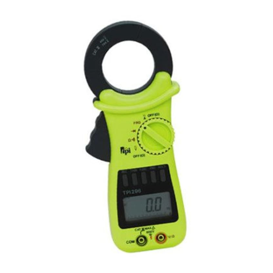
- Page 1 All manuals and user guides at all-guides.com Digital Clamp-on Meter Amp Plus Instruction Manual 1.800.561.8187 information@itm.com www. .com...
-
Page 2: Table Of Contents
All manuals and user guides at all-guides.com TABLE OF CONTENTS A. INTRODUCTION 1. Congratulations ......3 2. Product Description ....3 3. Declaration of Conformity ..4 B. SAFETY CONSIDERATIONS ....5 C. TECHNICAL DATA 1. Features and Benefits....7 2. Product Applications ....8 3. Specifications......9 D. -
Page 3: Introduction
All manuals and user guides at all-guides.com A. INTRODUCTION 1. Congratulations!! Thank you for purchasing TPI products. The Amp Plus is easy to use and is built to last. It is backed by a 3 year limited warranty. Please remember to complete and return your product warranty registration card. -
Page 4: Declaration Of Conformity
All manuals and user guides at all-guides.com 3. EC Declaration of Conformity This is to certify that TPI Model 296 conforms to the protection requirements of the council directive 89/336/EEC, in the approximation of laws of the member states relating to Electromagnetic compatibility and 73/23/EEC. -
Page 5: Safety Considerations
All manuals and user guides at all-guides.com B. SAFETY CONSIDERATIONS WARNING: Please follow manufacturers test procedures whenever possible. Do not attempt to mber measure unknown voltages or components until a complete understanding of the circuit is obtained. GENERAL GUIDELINES ALWAYS •... - Page 6 All manuals and user guides at all-guides.com INTERNATIONAL SYMBOLS CAUTION: RISK OF ELECTRIC SHOCK AC (ALTERNATION CURRENT) DC (DIRECT CURRENT) REFER TO INSTRUCTION MANUAL GROUND DOUBLE INSULATION EITHER DC OR AC 1.800.561.8187 information@itm.com www. .com...
-
Page 7: Technical Data
All manuals and user guides at all-guides.com C. TECHNICAL DATA 1. Features and Benefits Agency UL Listed to U.S. and Canadian Safety Standards. Meets CE and IEC 1010. True RMS Needed to accurately measure non-sinu- soidal AC voltage and current waveforms found on many controls and circuits. -
Page 8: Product Applications
All manuals and user guides at all-guides.com 2. Product Applications Perform the following tests and/or measurements with the 296 and the appropriate function: HVAC/R • Heat anticipator current in thermostats. • Line voltage. ACV or DCV • Control circuit voltage. OHMS •... -
Page 9: Specifications
All manuals and user guides at all-guides.com 3. Specifications IEC 1010 Over Voltage: CAT II - 1000V CAT III - 600V UL 3111-1 Pollution Degree 2 ats. a. DCV ity). Range Resolution Accuracy Impedance 0.01V ±0.75% of reading, 10Mohm 400V 0.1V ±3 digits 600V... - Page 10 All manuals and user guides at all-guides.com c. ACA Range Res. Accuracy Freq. Response Test 0.01A ±2% of reading, ±20 digits 45Hz to 60Hz ±4% of reading, ±20 digits 30Hz to 45Hz ±4% of reading, ±20 digits 60Hz to 1KHz 400A 0.1A ±2% of reading, ±10 digits 45Hz to 60Hz...
- Page 11 All manuals and user guides at all-guides.com g. Diode Test onse Test Voltage Max Test Current Over Load Protection Approx. 2.5mA 600 V DC or Peak AC h. Frequency Range Res. Accuracy Overload Protection 1KHz 0.1Hz ±0.2% of reading, 600V DC or 10KHz 0.001KHz ±3 digits...
-
Page 12: Measurement Techniques
All manuals and user guides at all-guides.com D. MEASUREMENT TECHNIQUES 1. Controls and Functions: Push Buttons TRIM Activates TRIM, PEAK and HDR functions (Except on Frequency Range). FUNC Toggles between AC and DC volts, amps and or functions. Activates manual ranging. Hold in for 2 seconds to return to autorange. - Page 13 All manuals and user guides at all-guides.com 1. Controls and Functions (cont.): Rotary Switch Turns the 296 completely off. Used to measure AC and DC volts. Ω Used to measure resistance and use the continuity buzzer. Used to measure diodes. olts, Used to measure the frequency of the current through the jaws.
- Page 14 All manuals and user guides at all-guides.com Application Notes When measuring DC Voltage of a bat- tery, the most accurate reading can be attained by testing the battery under load. To accomplish this, follow steps 1 through 4 shown on page 15 and the following (with the battery in holder and device turned on): •...
-
Page 15: Step By Step Procedures
All manuals and user guides at all-guides.com 2. Step by Step Procedures: a. Measuring DC Volts WARNING! Do not attempt to make a voltage measurement of more than 600V or of a voltage level that is unknown. Instrument set-up: FUNC. BLACK MAXI TEST LEAD TEST LEAD... - Page 16 All manuals and user guides at all-guides.com Application Notes Disconnect power from the terminal block, find the fuse or circuit breaker that controls the block and turn it off. Set up the meter following the steps under “Measurement Procedure” on page 17. Then proceed with the following: •...
- Page 17 All manuals and user guides at all-guides.com b. Measuring AC Volts WARNING! Do not attempt to make a voltage measurement of more than 600V or of a voltage level that is unknown. e or Instrument set-up: FUNC. BLACK TEST LEAD TEST LEAD READING READING V/Ω...
- Page 18 All manuals and user guides at all-guides.com d. Measuring DC Amps CAUTION! Do not attempt to make a current measurement with the test leads. The 296 measures the current by clamping the jaw around one conductor (wire). Clamping around more than one wire will result in erroneous readings. Instrument set-up: FUNC.
- Page 19 All manuals and user guides at all-guides.com Application Notes When measuring DC Amps of a motor there are two types of measurements that can be made, running current and in-rush or start-up current. Start-up current will usually be much higher than running current. Set up the meter following the steps under “Measurement Procedure”...
- Page 20 All manuals and user guides at all-guides.com c. Measuring AC Amps CAUTION! Do not attempt to make a current measurement with the test leads. The 296 measures the current by clamping the jaw around one conductor (wire). Clamping around more than one wire will result in erroneous readings.
- Page 21 All manuals and user guides at all-guides.com Application Notes When measuring AC Amps of a motor there are two types of measurements that can be made, running current and in-rush or start-up current. Start-up current will usually be much higher than running current. Set up the meter following the steps under “Measurement Procedure”...
- Page 22 All manuals and user guides at all-guides.com Application Notes (Resistance) Ω When measuring resistance of a motor, make sure the power is disconnected prior to testing. Set up meter following steps under “Measurement Procedure” on page 20, and proceed with the following: •...
- Page 23 All manuals and user guides at all-guides.com e. Measuring Resistance WARNING! Do not attempt to make resistance measurements with circuit energized. For best results, remove the resistor completely from circuit before attempting to measure it. NOTE: To make accurate low ohm measurements, short the ends of the test leads together and record the resistance reading.
- Page 24 All manuals and user guides at all-guides.com f. Continuity Buzzer WARNING! Do not attempt to make continuity measurements with circuit energized. Instrument set-up: FUNC. BLACK TEST LEAD TEST LEAD READING READING Ω V/Ω 0.001KΩ 4.000KΩ Measurement Procedure: 1. Disconnect power to circuit to be measured. 2.
- Page 25 All manuals and user guides at all-guides.com g. Measuring Diodes CAUTION! Do not attempt to make diode measurements with circuit energized. The only way to accurately test a diode is to remove it completely from the circuit before attempting to measure it. Instrument set-up: FUNC.
- Page 26 All manuals and user guides at all-guides.com h. Measuring Frequency CAUTION! Do not attempt to make frequency measurements with test leads. The 296 measures the frequency by clamp- ing the jaw around one conductor (wire). Clamping around more than one wire will result in erroneous read- ings.
- Page 27 All manuals and user guides at all-guides.com i. Data Hold Press the HOLD button at any time on any function to freeze the reading on the LCD display. This function is very useful when measuring in locations where the display is difficult to read. ead- j.
-
Page 28: Accessories
All manuals and user guides at all-guides.com l. Disable Sleep Mode 1. Set the 296 to the OFF position. 2. Push and hold down the HOLD button while turning the rotary switch to the desired function. 3. Release the HOLD button. 4. -
Page 29: Maintenance
All manuals and user guides at all-guides.com F. MAINTENANCE 1. Battery Replacement: The 296 will display a bat- tery symbol when the internal 9 Volt battery needs replacement. The battery is replaced as follows: a. Disconnect and remove all test leads from live circuits and from the 296. -
Page 30: Trouble Shooting Guide
All manuals and user guides at all-guides.com G. TROUBLE SHOOTING GUIDE Problem Probable Causes Does not power up • Dead or defective battery • Broken wire from battery snap to PCB Won’t display current readings • Open fuse • Open test lead •... - Page 31 All manuals and user guides at all-guides.com 1.800.561.8187 information@itm.com www. .com...
- Page 32 All manuals and user guides at all-guides.com 296 SPECIFICATIONS ±0.75% Basic DCV Accuracy Func. Range Res. 0.01V 400V 0.1V 600V 0.01V 400V 0.1V 600V 0.01A 400A 0.1A 700A 400A 0.1A 700A 0.001k 0.01k Frequency 1KHz 0.1Hz 10KHz 0.001KHz Continuity Test Voltage Max Test Current <...
Need help?
Do you have a question about the Amp Plus 296 and is the answer not in the manual?
Questions and answers