
Subscribe to Our Youtube Channel
Related Manuals for TPI 709R


Summary of Contents for TPI 709R
- Page 1 Combustion Efficiency Analyzer 709R The Value Leader www.tpi-thevalueleader.com...
-
Page 2: Table Of Contents
Contents Introduction General Overview Instrument Overview Front View Back View Side Views Top View Basic Analyzer Controls Turning The Analyzer On Turning The Analyzer Off Charging The Analyzer Activating The Backlight Combustion Analysis Overview Procedure Combustion Displays Typical Test Locations Typical Test Results Function Selection Function 1 - Thermometer... -
Page 3: General Overview
This warranty does not cover sensors damaged through misuse of the analyzer. You should keep the batteries of your 709R fresh so power is con- stantly being supplied to your sensors. The following guidelines will help prevent damage to your sensors: Always use the mini pump filter when testing flue gases. - Page 4 Always keep the A794 water trap / filter assembly clean and replace the fil- ter as necessary. Replacement filter part number is A794F. This manual will guide you through the functions of the TPI 709R which will give you many years of reliable service.
-
Page 5: Instrument Overview
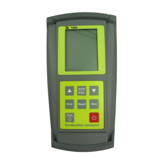
3. Instrument Overview 3.1 Front View Rubber Boot Display Battery Condition Icon Selected Fuel Type Keypad Rubber Boot Protects the instrument from accidental damage Display Large 3 Parameter Backlit LCD Display Battery Condition Icon Shows condition of batteries. Keypad Selects all available functions Selected Fuel Type N GAS, LPG, LIGHT OIL, HEAVY OIL, OPT 1 (Bituminous Coal), OPT 2 (Anthracite Coal),... - Page 6 Scrolls through selectable fuels (see 3.1 ) Switches between Gross and Newt Efficiency (see 4.1.2) Switches between ºC and ºF (see 4.2.1) Moves up through the Stored Data Addresses (see 5, 6 & 7) Moves down through the Stored Data Addresses (see 5, 6 & 7) Scrolls through Combustion Analysis Displays Scroll Scrolls through Function Screens (see 4.1)
-
Page 7: Back View
3.2 Back View Connections for Connection for Pressure Tubing Mini Pump Protection Filter Sample and Calibration and Pressure Inlet Information Ports Label Rubber Boot Battery Compartment Sample and Pressure Inlet Ports: Connection for Gas Sampling Probe (see 3.4, 5.2, 6.2) Connection for Mini Pump Protection Filter (see 3.4 &... -
Page 8: Side Views
Exhaust Port Infrared Window Rubber Boot 3.3 Side Views Exhaust Port Port for connection of Exhaust Adapter Infrared Window Window for sending stored data to IR Printer (see 9) Rubber Boot Protects the instrument from accidental damage... -
Page 9: Top View
3.4 Top View Charger Socket P (+) P (-) Gas Sampling Port Charger Socket Connection for 220V/115V charger (see 4.3) T1 Socket Connection for thermocouple plug on flue probe (see 5.2) Connection for any 'K' type thermocouple probe (see 6.1) T2 Socket Connection for any 'K' type thermocouple probe (see 5.2 &... -
Page 10: Basic Analyzer Controls
Pressure or Leak Detection readings and Combustion Display 1 will be the first display. The 709R will auto power off if no keys have been pressed for 10 minutes and the CO level is below 15ppm. This feature can be disabled see Appendix F. -
Page 11: Turning The Analyzer Off
6 hours Operating Time. If a beeping noise is heard during charging disconnect the charger. This is an indication the battery pack needs to be replaced or of something wrong in the charging circuit. Please contact TPI technical assis- tance at 800-368-5719. -
Page 12: Combustion Analysis Overview
To ensure accurate and consistent combustion tests, it is important gas and tem- perature samples be taken at the same location. This is easy with the TPI flue probe because the temperature sensor is an integral part of the probe. -
Page 13: Procedure
COMBUSTION ANALYSIS (Continued) 5.1 Procedure 1. Turn the 709R on as outlined in section 4.1. At any time you can activate the Backlight by holding down the Func/Backlight Key for 2 seconds. The backlight will automatically shut off after 20 seconds to preserve battery life. -
Page 14: Combustion Displays
COMBUSTION ANALYSIS (Continued) 4. As seen below, use the Scroll/Enter Key to move through the various com- bustion displays. 5.2 Combustion Displays You can move through the following Combustion Analysis Screens by repeat- edly pressing Scroll/Enter: • Combustion Display 1 (Default Start Up Display) •... - Page 15 COMBUSTION ANALYSIS (Continued) 5.2 Combustion Displays (continued) • Combustion Display 4 • Displays CO air free (-CF-) • Combustion Display 5 • Displays Temperature reading of Channel 1 (T1) in degrees Centigrade (ºC) • Displays Temperature reading of Channel 2 (T2) in degrees Centigrade (ºC) •...
-
Page 16: Typical Test Locations
COMBUSTION ANALYSIS (Continued) 5.3 TYPICAL TEST LOCATIONS Atmospheric Gas Fired Fan Assist Boiler / Furnace Typical Test Locations Figure 1... - Page 17 COMBUSTION ANALYSIS (Continued) Condensing Boiler / Furnace Typical Test Locations Figure 2...
- Page 18 COMBUSTION ANALYSIS (Continued) Atmospheric Forced Air Furnace Typical Test Locations Test all exhaust ports at the top of the heat exchanger. Figure 3...
-
Page 19: Typical Test Results
COMBUSTION ANALYSIS (Continued) 5.4 TYPICAL TEST RESULTS Actual test results vary depending on the equip- ment under test. TPI recommends you check with the manufacturer of the equipment being tested to determine specific acceptable results. Power Burners (Gas Fired) Oxygen... -
Page 20: Function Selection
Manometer, and Date / Time display. 6.1 Function 1: - Thermometer Press the Func Key repeatedly to access the thermometer function. In this mode the 709R functions like a K-Type thermocouple thermometer. The pump will stop running when in this function. Function 1 Display (Temperature) -
Page 21: Function 2 - Manometer
The 709R incorporates a differential manometer. This means when a single hose is connected to the (+) port and pressure is applied, the 709R will read positive pressure. If a single hose is connected to the (-) port and pressure is applied, the 709R will read a negative pressure. -
Page 22: Function 3: - Date/Time
6.3 Function 3: - Date/Time Press the Func Key repeatedly to access the date/time screen. From this func- tion Time, Date and Year can be changed. Function 3 Display (Date / Time) Time Date / Month Year 1. Once the Time, Date, and Year screen is displayed, press the Scroll/Enter Key once to allow you to change the data. -
Page 23: Saving Data
7. SAVING DATA During testing data can be stored for later retrieval. When data is saved, all data previously in the address will be overwritten.When saving pressure/draft readings, select an address different from the one used to save combustion readings. 1. -
Page 24: Recalling Data
3. Using the up and down arrows, select the memory location of the readings you want to display. 4. Press the Scroll/Enter key once. The 709R will display the date and time screen showing when that reading was stored. 5. Use the up and down arrows to scroll through the data that was saved. -
Page 25: Printing Data
‘rEAL’ will be flashing. To cancel printing press the Print Key and use the Up/Down Arrow Keys to select “Yes” and press the Scroll/Enter Key. Selecting ‘rEAL’ will cause the 709R to print the test data currently on the display (real time data). Selecting ‘Stor’ will cause the 709R to print data stored in memory. - Page 26 PRINTING DATA (Continued) Printout Interpretation Date and time of combustion test. Fuel type selected during test. Data from combustion test is printed here. Smoke Test Result. For use on oil fired equip- ment. (Circle one to indicate the result of a smoke test performed using the optional A788 smoke test pump.)
-
Page 27: Appendix A Specifications
Appendix A : SPECIFICATIONS Instrument Operating Temperature Range 14°F to +122°F (-10°C to +50°C) Battery 1.5V AA size (3) Battery Life > 6 Hours Fuels Natural Gas, LPG, Light Oil, Heavy Oil OPT 1 (Bituminous Coal), OPT 2 (Anthracite Coal), OPT 3 (Coke), OPT 4 (Butane), OPT 5 (Wood), OPT 6 (Bagasse) Display... - Page 28 Appendix A : SPECIFICATIONS (Continued) Pressure Measurement Selectable Ranges mbar, kPa and inH2O Range - 150 mbar to + 150 mbar -15 kPa to + 15 kPa -60 inH O to 60 inH Resolution 0.01 mbar, 0.001 kPa, 0.001 inH Accuracy +/- 0.5% fsd Temperature Measurement...
-
Page 29: Appendix B Calibration & Service
A764 Appendix C: GUARANTEE Your TPI 709R Flue Gas Analyzer is guaranteed free from defects in materials and workmanship for 3 Years from the date of purchase. This guarantee does not affect your statuary rights. For additional information please refer to the included warranty card or contact TPI at 800-368-5719. -
Page 30: Appendix D Installing The Optional A773 Filter
Appendix D: INSTALLING THE OPTIONAL A773 OIL FILTER When performing combustion tests on oil fired equipment it is important to use the optional A773 oil filter to ensure stable readings. The A773 does not have to be removed when working with other types of fuels. PROCEDURE 1. - Page 31 Appendix E: ERROR CODES & TROUBLESHOOTING The 709R analyzer will display certain codes to let you know of a malfunction. Code Code Definition Possible Causes Corrective Action Displayed Pump not drawing sample at Blockage / kink in flue probe Check and rectify.
- Page 32 Appendix E: ERROR CODES & TROUBLESHOOTING (Continued) Problem Possible Cause Corrective Action Efficiency reading incorrect NET efficiency selected. Select GROSS efficiency. See section 5.3. Ambient temperature probe Plug ambient probe into T2. not plugged in to T2. See section 5.2. Incorrect fuel selected.
- Page 33 6. 709R Display: ‘20.9%’, ‘o2’, ‘rEF’. Action : Press the Func Key to bypass. 7. 709R Display: ‘2000’, ‘A-r’, ‘SEt’. Action : If you are not changing the CO alarm point press the Func Key. Otherwise press the Up and Down Keys to set the ppm level the alarm will sound at.
-
Page 34: Appendix G Manually Initializing Sensors
8. 709R Display: ‘Auto’, ‘oFF’, ‘En’. Action : Press the Func Key to bypass. 9. 709R Display: ‘CAL’, ‘StoP’, ‘go’. Action : Press the Up Arrow Key to select ‘StoP’ by making it blink and press the Scroll/Enter Key to accept the selec- tion. -
Page 35: Appendix H Resetting Pressure Sensor Zero
WARNING : Changing parameters in field calibration mode can adversely affect the operation of your analyzer. Follow the instructions carefully. 1. Press and hold the Scroll/Enter Key down intil ‘FILD CAL’ is displayed. The 709R will cycle through a 30 second countdown then display ‘CAL’, Air’, gAS’. -
Page 36: Technical Notes
Appendix I: Technical Notes Note 1: When performing a pressure or draft test during a combustion test, the pump can be turned on to provide a continuous sample to the sensors. This enables pressure adjustments to be made and the affect to the combustion process can be seen by returning to combustion analyzer mode. - Page 37 Notes:...
- Page 38 Notes:...
- Page 39 Notes:...
- Page 40 Test Products International, Inc. 9615 SW Allen Blvd., Ste. 104 Beaverton, OR 97005 Tel: 503-520-9197 Fax: 503-520-1225 www.tpi-thevalueleader.com Test Products International, Ltd. 342 Bronte Road South, Unit #9 Milton Ontario Canada L9T5B7 Tel: 905-693-8558 Fax: 905-693-0888...
Need help?
Do you have a question about the 709R and is the answer not in the manual?
Questions and answers