
Related Manuals for TPI 716


Summary of Contents for TPI 716
- Page 1 Flue Gas Analyser TPI 716 The Value Leader GlobalTestSupply www. .com Find Quality Products Online at: sales@GlobalTestSupply.com...
-
Page 2: Table Of Contents
Contents Introduction............1 General Overview..........1, 2 Instrument Overview..........3 ~ 7 Front View..........3 Keypad...........4 Back View..........5 Side Views..........6 Top View..........7 Basic Analyser Functions........8 ~ 10 Charging The Analyser........8 Turning The Analyzer On ......9 & 10 Measurements............ 11 ~ 24 Flue Gas.......... -
Page 3: Introduction
Always use the optional oil filter (p/n A773) when performing tests on oil burning equipment unless you are using the 716 with an NO sensor fitted. Do not use the A773 on the 716 with NO sensor fitted because the A773 will filter out Nitric Oxide (NO). - Page 4 General Overview (Continued) This manual will guide you through the functions of the TPI 716 which will give you many years of reliable service. Your TPI 716 Flue Gas Analyser comes complete with the following standard accessories: ( ) Denotes part number •...
-
Page 5: Instrument Overview
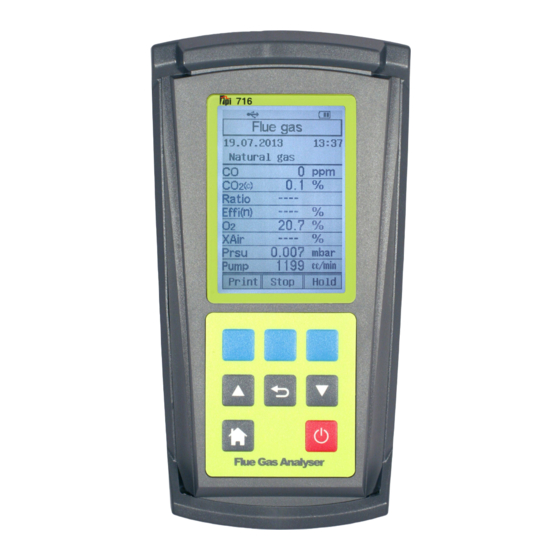
Instrument Overview Front View Rubber Boot Display Keypad Rubber Boot Protects the instrument from accidental damage Display Large graphical backlit LCD Display Keypad Selects all available functions GlobalTestSupply www. .com Find Quality Products Online at: sales@GlobalTestSupply.com... -
Page 6: Keypad
Keypad Blue Soft Keys - The function of these keys is shown in the lower part of the display and changes depending on what menu the analyser is in. In the picture center soft key controls the start function and the left and right soft keys are disabled. -
Page 7: Back View
Back View Thermocouple Gas, Pressure, USB & Sockets Leak Probe Ports Information Label Calibration Information Rubber Boot Exhaust Port Infrared Window Battery Compartment Calibration and Information Label: Displays calibration information and serial number Battery Compartment: Holds rechargeable battery Rubber Boot Protects the instrument GlobalTestSupply www. -
Page 8: Side Views
Side Views Left Hand Right Side Hand Side Rubber Boot Exhaust Port Infrared Window Rubber Boot Exhaust Port Port for connection of Exhaust Adapter Infrared Window Window for sending stored data to IR Printer Rubber Boot Protects the instrument from accidental damage GlobalTestSupply www. -
Page 9: Top View
Gas Sample Port Connection for Mini Pump Protection Filter and Flue Probe P (+) Port Connections for Pressure Tubing P (-) Port USB Port Connection for A807 cable for communication to a PC or connection for 716-Leak combustible gas leak detection sniffer probe. GlobalTestSupply www. .com Find Quality Products Online at:... -
Page 10: Basic Analyser Functions
BASIC ANALYSER FUNCTIONS Charging The Analyser Plug the charger into the charger socket on the instrument (see page 7). When the charger is plugged in the battery level display will turn on. This display indicates the analyser is being charged and the status of the charge. The plug symbol confirms the analyser is connected to the charger. -
Page 11: Turning The Analyzer On
Date Last Calibration was carried out Date Next Calibration is due After approximately 5 seconds the Main menu will be displayed & the 716 is ready to use. However, as the Next Calibration Due Date Approaches or is Overdue one... - Page 12 Turning The Analyser On (continued) Choosing “Next” will move you onto the Main Menu Screen as displayed below. Please Note: It is a requirement of BS7967 that an FGA is within calibration and used in conjunction with the manufacturers instructions therefore it is NOT recommended that “Next”...
-
Page 13: Measurements
Note: It is recommended you perform routine general maintenance on your analyser to ensure proper function. Please refer to Appendix A for further details Turn the 716 on as outlined on page 9. After the initial start up screen the Main Menu will be displayed. - Page 14 NOTE: When selecting oil as fuel be sure to use the optional oil filter (A773) or readings could become erratic. See Appendix E for installation instructions. Do NOT use the A773 with a 716 analyser with the NO Sensor Upgrade. GlobalTestSupply www.
- Page 15 MEASUREMENTS - Flue Gas (continued) The unit of efficiency can be changed as needed between Nett, Gross & Condensing. Nett efficiency doesn’t take into account wet losses while Gross efficiency does. Condensing efficiency is a common calculation applied is some European Countries. Press the right soft key (Next) to highlight “Efficiency change”...
- Page 16 MEASUREMENTS - Flue Gas (continued) Connect the Gas Sampling Flue Probe Tubing complete to the In-Line Pump Protection Filter (see below) and the 'K' Type Thermocouple Plug from the Flue Probe into Thermocouple (T1) Socket. The GK11M ambient air temperature probe is connected to the (T2) socket.
- Page 17 MEASUREMENTS - Flue Gas (continued) Insert the flue probe into the sample hole of the device under test. The probe tip should be in the middle of the flue pipe or exhaust stream. Ensure the In-Line Filter / Water Trap hangs below the analyser in the proper vertical position when readings are being taken.
- Page 18 MEASUREMENTS - Flue Gas (continued) Allow the readings to stabilise. Multiple parameters can be seen in the display. • Carbon Monoxide (CO) reading in parts per million (ppm) • Carbon Dioxide (CO2) figure in percentage (%) (calculated) • CO/CO2 (Ratio) figure. •...
- Page 19 “unHold” option is chosen. You can “Save”, “Print” or “Send” out as many sets of these readings as you require whilst the 716 is in “Hold” mode. Once the “unHold” button is pressed then the 716 will return to Live readings as explained on Page 16.
-
Page 20: Temperature & Pressure
Measurements - Temperature & Pressure From the Main menu screen using the Up / Down Arrow keys select “Measurements” in the menu. Press “Enter” (center blue soft key) to confirm the selection. From the Measurements menu use the Up / Down Arrow keys to select “Temp/Pressure”... - Page 21 Measurements - Temperature & Pressure (continued) Measuring Temperature - 1. Ensure you have a 'K' type probe connected to one or both of the thermocouple sockets T1 / T2 (refer to figure below) WARNING: - There is ONLY one correct way to connect the 'K' type thermocouple plug into the socket (see page 7).
- Page 22 1. Ensure you have Pressure Sampling Tube connected to one or both of the Pressure Ports and there are no restrictions in the tubing (see figure below). The 716 is supplied with a pair of pressure adaptors to allow 1/4” bore hose to be attached to the pressure ports.
-
Page 23: Co Room Test
Measurements - CO Room Test The CO room test function enables the 716 to monitor and log ambient CO levels in a room or office space at 1 minute intervals. This data can be retrieved later via the optional infrared printer or serial cable and software. -
Page 24: Tightness Test
6. Connect the pressure tube to the desired test point and pressure up the 716 to the required pressure. The Live Pressure Readings can be viewed in the top box on all the following screens. - Page 25 “Pass” them and move onto the Stabilisation part of the test. 10. Pressure up the 716 to the required pressure. The Live Pressure Readings can be viewed in the top box on all the following screens.
-
Page 26: Combustible Gas Leak Detection
Measurements - Leak Detection The Leak Detection function enables the 716 to test for combustible gas leaks in gas valves and fittings using the included gooseneck probe. 1. Connect the combustible gas probe to the USB connector located on the top of the 716. -
Page 27: Menu Navigation
Menu Navigation - Memory From the Main menu there are several sub menus that allow analyser set up, memory maintenance and other parameters to be accessed. Here is a list of each and what function they perform. 1. Memory can be accessed from the main menu to enable maintenance to be performed. -
Page 28: Fuel Type
Menu Navigation - Fuel Type 1. From the main menu use the Arrow keys to select “Fuel Type” and press the “Enter” key (center blue soft key). 2. Use the Arrow keys to select the fuel type. Scrolling down displays the rest of the available fuel types. -
Page 29: Analyzer Setup
Backlight - Adjust the backlight level from off to full brightness or set it to auto and the 716’s internal sensor will control the backlight brightness depending on ambient light. Alarm limits - Set the level at which the CO alarms sounds. -
Page 30: Units Of Measure, Instrument Info
Menu Navigation - Units of Measure 1. From the main menu use the Arrow keys to select “Units of Measure” and press the “Enter” key (center blue soft key). 2. The Units of Measure menu will display. The following parameters are accessible in this menu. -
Page 31: Turning The Analyzer Off
NOTE The Instrument will not allow itself to be switched off if the CO is above 10ppm When the 716 is turning off the following screen is seen: The instrument has an auto shut off factory set for 10 minutes should no keys have been pressed for this period and the CO level is below 10ppm. -
Page 32: Specifications
SPECIFICATIONS Instrument Operating Temperature Range 14°F to +122°F (-10°C to +50°C) Battery / Battery Life Rechargeable Ni-MH / > 6 Hours Charger Input Voltage 115V or 230V : 50/60 Hz AC Fuels Natural Gas, LPG, Light Oil, Heavy Oil, Bituminous Coal, Anthracite Coal, Coke, Butane, Wood, Bagasse Pressure Ranges mbar, psi, inH2O, mmH2O, kPa, hPa,... - Page 33 SPECIFICATIONS (Continued) Gases Range Resolution Accuracy Oxygen 0-25% 0.1% +/- 0.3% Carbon Monoxide (low) 0-10,000 ppm 1 ppm (<100ppm) +/- 5 ppm (>=100ppm) +/- 5% Carbon Monoxide (high)* 0-100,000 ppm 0.001% >10,000ppm: +/- 10% Nitric Oxide * 0-5000ppm 1ppm +/- 5ppm (<100ppm) +/- 5% (<1000ppm) +/- 10% (>1000ppm) Carbon Dioxide...
-
Page 34: Calibration & Service
A763 WARRANTY Your TPI 716 Flue Gas Analyser is guaranteed free from defects in materials and workmanship for 6 Years from the date of purchase subject to the unit being returned annually and serviced/calibrated by TPI or an approved Service Centre. - Page 35 Signs of dirty or water saturated filters are a slow pump, flow error displayed when the flue probe is connected, and measurements that take longer than normal. TPI analysers use three filters to protect the pump and sensors. The first filter to check is the A763 mini pump protection filter. (see picture below)
- Page 36 Appendix A: General Maintenance (continued) Filter Check Continued The other two filters are located in the water trap. The main filter is the A796-F particle filter. This filter stops debris and dust from traveling down to the analyser. The secondary filter is the A794-D water block filter. This filter stops flow in the event the water trap fills with condensate.
- Page 37 Appendix A: General Maintenance (continued) Flue Probe Integrity Check NOTE: Perform this check AFTER performing the Pump Operation Check outlined on the previous page. 1. Turn the analyser on as outlined on page 9. Wait until the analyser has completed the initial purge and sensor check and is operating normally prior to proceeding to step 2.
-
Page 38: Appendix B Error Codes And Troubleshooting
Replace filter(s). See Appendix A. Worn pump. Call Technical Helpline on 01293 530196 opt. 1 Oxygen sensor failed to Disconnect probe and Flue probe connected to 716 Sensor initialize prior to power up. restart. Error 716 did not purge completely Purge for 20 minutes and from last sample. -
Page 39: Error Codes And Troubleshooting
Appendix B: ERROR CODES & TROUBLESHOOTING (Continued) Problem Possible Cause Corrective Action Efficiency reading incorrect NET/GROSS efficiency incorrectly Select correct efficiency. selected. Plug ambient probe into T2. See Ambient temperature probe not page 14. plugged in to T2. Select the proper fuel for the Incorrect fuel selected.
Need help?
Do you have a question about the 716 and is the answer not in the manual?
Questions and answers