
Related Manuals for TPI The Value Leader 716N


Summary of Contents for TPI The Value Leader 716N
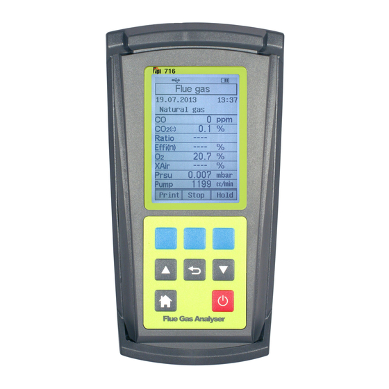
- Page 1 Flue Gas Analyzer 716 / 716N The Value Leader www.tpi-thevalueleader.com...
-
Page 2: Table Of Contents
Contents Notes: Introduction............1 General Overview..........1, 2 Instrument Overview..........3 ~ 7 Front View..........3 Keypad...........4 Back View..........5 Side Views..........6 Top View..........7 Basic Analyzer Functions........8 ~ 10 Charging The Analyzer........ 8 Turning The Analyzer On ......9 Turning The Analyzer Off......10 Display Backlight........ -
Page 3: Introduction
Notes: Introduction Thank you for purchasing TPI brand products. The TPI 716 Flue Gas Analyzer is a state of the art, easy to use analyzer designed not only to display and calculate the required readings from a flue but also to cover most of the other measurements associated with combustion. - Page 4 Always keep the A795 water trap / filter assembly clean and replace the filter as necessary. Replacement filter part number is A794F. This manual will guide you through the functions of the TPI 716 which will give you many years of reliable service.
-
Page 5: Instrument Overview
For best results use a TPI replacement battery part number A007. The battery in your analyzer is 3.6V NiMH 1600mAh rated. Never replace the battery with any Rubber other type of battery or damage to the charge circuit will result. -
Page 6: Keypad
Keypad Appendix F: CARBON MONOXIDE FACTS Carbon Monoxide (CO) is invisible, odorless, and tasteless. It is the byproduct of Blue Soft Keys - The function of these keys is shown in the combustion and levels are elevated when there is incomplete combustion. lower part of the display and changes depending on what menu the analyzer is in. -
Page 7: Back View
Appendix E: Carbon Monoxide in Ambient Air Chart Back View This chart contains maximum exposure levels and times for carbon monoxide. This is a general guideline only. It is recommended you check with your local government for guidelines in your area. Calibration and Information Label... -
Page 8: Side Views
Side Views Appendix D: Testing for Carbon Monoxide in Ambient Air The 716 can be used to test for carbon monoxide in ambient air. For example tests can be performed in work spaces and living areas like offices and houses to ensure safety. -
Page 9: Top View
Battery will not charge or hold a Defective charger or battery. Replace the charger or battery. charge. Send to TPI for service. T2 Socket Connection for ambient 'K' type thermocouple probe Beeping noise heard during charg- Defect in charging circuit or shorted Disconnect from the charger and ing. -
Page 10: Basic Analyzer Functions
Replace filter(s). See Appendix A. er is connected to the charger. The Worn pump. Return to TPI for service. battery symbol shows the charge level when the analyzer is on too. Oxygen sensor failed to ini- Flue probe connected to 716... -
Page 11: Turning The Analyzer On
Appendix B: Turning The Analyzer On A773 SULFUR FILTER INSTALLATION & MAINTENANCE Always: - Before turning on please ensure nothing is connected to the Gas 4. Beginning on the “Flue Probe” side of the A773 sulfur filter, pull the yellow Sample Port (see page 7) thermocouple cord out of the channel of the flue probe tube. -
Page 12: Turning The Analyzer Off
Turning The Analyzer Off Appendix B: A773 SULFUR FILTER INSTALLATION & MAINTENANCE USE THE A773 ONLY WITH THE 716. DO NOT USE WITH THE 716N. Always: - Before turning off return the instrument to a clean air environment and allow the Carbon Monoxide level to return below 15ppm and the Oxygen When using a 716 and performing combustion tests on oil fired equipment it level to return to 20.9% (±... -
Page 13: Combustion Analysis Overview
This is inlet of the analyzer and the yellow thermocouple connector to input T1. easy with the TPI flue probe because the temperature sensor is an integral part of the probe. -
Page 14: Measurements
MEASUREMENTS - Flue Gas Appendix A: General Maintenance (continued) Note: It is recommended you perform routine general maintenance on your Filter Check Continued analyzer to ensure proper function. Please refer to Appendix A for general The other two filters are located in the water trap. The main filter is the A794F maintenance schedule and function tests. -
Page 15: Measurements
The unit of efficiency can be changed as needed between Nett and Gross. Nett eficiency doesn’t TPI analyzers use three filters to protect the pump and sensors. The first filter to take into account wet losses while Gross efficien- check is the A763 mini pump protection filter. (see picture below) cy does. - Page 16 Flue Probe WARRANTY Your TPI 716 Flue Gas Analyzer is guaranteed free from defects in materials and workmanship for 3 Years from the date of purchase. The sensors carry a 2 Year warranty. This guarantee does not affect your statuary rights. For addi- tional information please refer to the included warranty card or contact TPI at 800-368-5719.
- Page 17 SPECIFICATIONS (Continued) MEASUREMENTS - Flue Gas (continued) IMPORTANT: Prior to taking a sample, the device under test should be on and Gases Range Resolution Accuracy at operating temperature. Putting the flue probe in the sample area prior to Oxygen 0-25% 0.1% +/- 0.3% starting the device may cause saturation of the sensors due to the higher...
- Page 18 SPECIFICATIONS MEASUREMENTS - Flue Gas (continued) Instrument TYPICAL TEST LOCATIONS Operating Temperature Range 14°F to +122°F (-10°C to +50°C) Battery / Battery Life Rechargeable Ni-MH / > 6 Hours Charger Input Voltage 115V or 230V : 50/60 Hz AC Atmospheric Gas Fired Fan Assist Boiler / Furnace Fuels Natural Gas, LPG, Light Oil, Heavy Oil, Bituminous Coal, Anthracite Coal, Coke,...
- Page 19 Menu Navigation - Units of Measure MEASUREMENTS - Flue Gas (continued) 1. From the main menu use the Arrow keys to select “Units of Measure” and TYPICAL TEST LOCATIONS press the “Enter” key (center blue soft key). 2. The Units of Measure menu will display. The following parameters are accessi- ble in this menu.
- Page 20 Menu Navigation - Analyzer Setup MEASUREMENTS - Flue Gas (continued) TYPICAL TEST LOCATIONS 1. From the main menu use the Arrow keys to select “Analyzer Setup” and press the “Enter” key (center blue soft key). Atmospheric Forced Air Furnace 2. The Analyzer Setup menu will display. The following parameters are accessible in this menu.
- Page 21 Menu Navigation - Fuel Type MEASUREMENTS - Flue Gas (continued) Insert the flue probe into the sample hole of the device under test. The probe tip should be in the middle of the flue pipe or exhaust stream. 1. From the main menu use the Arrow keys to select “Fuel Type”...
- Page 22 MEASUREMENTS - Flue Gas (continued) Menu Navigation - Memory Allow the readings to stabilize. Multiple parameters can be seen in the display. From the Main menu there are several sub menus that allow analyzer set up, memory maintenance and other parameters to be accessed. Here is a list of each •...
- Page 23 Measurements - Leak Detection MEASUREMENTS - Flue Gas (continued) The Leak Detection function enables the 716 to test for combustible gas leaks in Test data can be saved to a memory location if gas valves and fittings using the included gooseneck probe. required.
-
Page 24: Typical Test Results
Actual test results vary depending on the equipment under the optional infrared printer or serial cable and software. test. TPI recommends you check with the manufacturer of the 1. Begin with the 716 in a fresh air environment equipment being tested to determine specific acceptable outside of the test area. -
Page 25: Temperature & Pressure
Measurements - Temperature & Pressure (continued) Measurements - Temperature & Pressure Tightness Test - From the Main menu screen using the Up / Down Arrow keys select “Measurements” in the menu. The tightness test function enables the 716 to check for pressure leaks in valves, fittings, and pressure switches with an elapsed time reference. -
Page 26: Memory
Measurements - Temperature & Pressure (continued) Measurements - Temperature & Pressure (continued) Measuring Temperature - Measuring Pressure - 1. Ensure you have a 'K' type probe connected to one or both of the thermo- 1. Ensure you have Pressure Sampling Tube connected to one or both of the couple sockets T1 / T2 (refer to figure below) Pressure Ports and there are no restrictions in the tubing (see figure below) WARNING: - There is ONLY one correct way to connect the 'K' type thermo-...
Need help?
Do you have a question about the The Value Leader 716N and is the answer not in the manual?
Questions and answers