Table of Contents
Advertisement
Quick Links
Advertisement
Table of Contents

Related Manuals for TPI Amp Plus 291


Summary of Contents for TPI Amp Plus 291
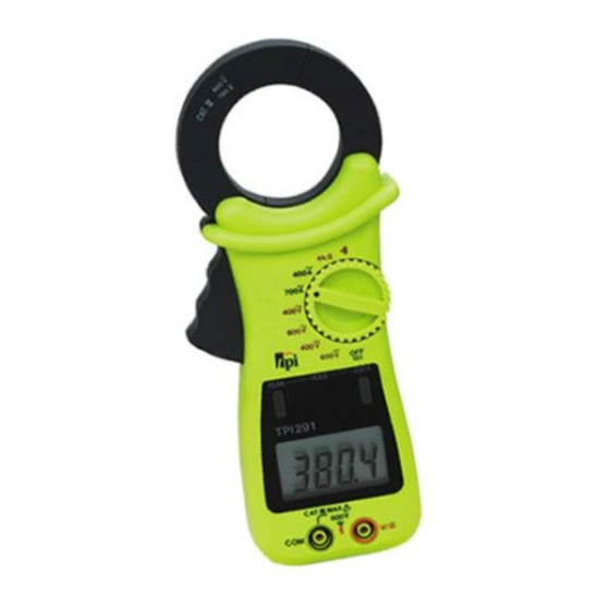
- Page 1 Digital Clamp-on Meter Amp Plus Instruction Manual...
-
Page 2: Table Of Contents
TABLE OF CONTENTS A. INTRODUCTION 1. Congratulations ......3 2. Product Description ....3 3. Declaration of Conformity ..4 B. SAFETY CONSIDERATIONS ....5 C. TECHNICAL DATA 1. Features and Benefits....6 2. Product Applications ....7 3. Specifications......8 D. MEASUREMENT TECHNIQUES 1. Controls and Functions ....10 2. -
Page 3: Introduction
A. INTRODUCTION 1. Congratulations!! Thank you for purchasing TPI products. The Amp Plus is easy to use and is built to last. It is backed by a 3 year limited warranty. Please remember to complete and return your product warranty registration card. -
Page 4: Declaration Of Conformity
3. EC Declaration of Conformity This is to certify that TPI Model 291 conforms to the protection requirements of the council directive 89/336/EEC, in the approximation of laws of the member states relating to Electromagnetic compatibility and 73/23/EEC. The Low Voltage Directive by application of... -
Page 5: Safety Considerations
B. SAFETY CONSIDERATIONS WARNING: Please follow manufacturers test procedures whenever possible. Do not attempt to measure unknown voltages or components until a complete understanding of the circuit is obtained. GENERAL GUIDELINES ALWAYS • Test the 291 before using it to make sure it is operating properly. -
Page 6: Technical Data
INTERNATIONAL SYMBOLS CAUTION: RISK OF ELECTRIC SHOCK AC (Alternation Current) DC (Direct Current) REFER TO INSTRUCTION MANUAL GROUND DOUBLE INSULATION EITHER DC OR AC C. TECHNICAL DATA 1. Features and Benefits Agency UL Listed to U.S. and Canadian Safety Standards. Meets CE and IEC 1010. -
Page 7: Product Applications
2. Product Applications Perform the following tests and/or measurements with the 291 and the appropriate function: HVAC/R • Heat anticipator current in thermostats. • Line voltage. ACV or DCV • Control circuit voltage. OHMS • Heating element resistance (continuity). OHMS •... -
Page 8: Specifications
3. Specifications IEC 1010 Over Voltage: CAT II - 1000V CAT III - 600V UL 3111-1 Pollution Degree 2 a. DCV Range Resolution Accuracy Impedance 0.01V ±0.75% of reading, 10MΩ 400V 0.1V ±3 digits 600V b. ACV Range Resolution Accuracy Impedance 400V 0.1V... - Page 9 e. OHM (Resistance, ) Range Res. Accuracy Overload Protection 400Ω 0.1Ω ±1% of reading, ±10 digits 600V DC or AC Peak f. Continuity Buzzer Test Voltage Threshold Over Load Protection < 50Ω (100 digits) 600 V DC or Peak AC h.
-
Page 10: Measurement Techniques
D. MEASUREMENT TECHNIQUES 1. Controls and Functions: Push Buttons PEAK Activates the Peak Hold function (ACA only.) HOLD Holds the reading on the display until the button is pushed a second time. Rotary Switch Turns the 291 completely off. Used to measure DC volts. Used to measure AC volts. - Page 11 1. Controls and Functions: (cont.) Input Jacks Black test lead connection for ACV, DCV, Ω, Continuity Buzzer and Diode Test functions. V/ Ω Ω Red test lead connection for all ACV, DCV, Ω , Continuity Buzzer and Diode Test functions.
- Page 12 Application Notes When measuring DC Voltage of a bat- tery, the most accurate reading can be attained by testing the battery under load. To accomplish this, follow steps 1 through 4 shown on page 13 and the following (with the battery in holder and device turned on): •...
-
Page 13: Step By Step Procedures
2. Step by Step Procedures: a. Measuring DC Volts WARNING! Do not attempt to make a voltage measurement of more than 600V or of a voltage level that is unknown. Instrument set-up: FUNC. BLACK MAXI TEST LEAD TEST LEAD READING READING V/Ω... - Page 14 Application Notes Disconnect power from the terminal block, find the fuse or circuit breaker that controls the block and turn it off. Set up the meter following the steps under “Measurement Procedure” on page 15. Then proceed with the following: •...
- Page 15 b. Measuring AC Volts WARNING! Do not attempt to make a voltage measurement of more than 600V or of a voltage level that is unknown. Instrument set-up: FUNC. BLACK TEST LEAD TEST LEAD READING READING V/Ω 0.1mV 750V Measurement Procedure: 1.
- Page 16 c. Measuring AC Amps CAUTION! Do not attempt to make a current measurement with the test leads. The 291 measures the current by clamping the jaw around one conductor (wire). Clamping around more than one wire will result in erroneous readings. Instrument set-up: FUNC.
- Page 17 Application Notes When measuring AC Amps of a motor there are two types of measurements that can be made, running current and in-rush or start-up current. Start-up current will usually be much higher than running current. Set up the meter following the steps under “Measurement Procedure”...
- Page 18 Application Notes (Resistance) When measuring resistance of a motor, make sure the power is disconnected prior to testing. Set up meter following steps under “Measurement Procedure” on page 19, and proceed with the following: • Connect the red test lead to one power input line of the motor and the black test lead to the other power input line of the motor.
- Page 19 d. Measuring Resistance WARNING! Do not attempt to make resistance measurements with circuit energized. For best results, remove the resistor completely from circuit before attempting to measure it. NOTE: To make accurate low ohm measurements, short the ends of the test leads together and record the resistance reading.
- Page 20 e. Continuity Buzzer WARNING! Do not attempt to make continuity measurements with circuit energized. Instrument set-up: FUNC. BLACK TEST LEAD TEST LEAD Ω V/Ω Measurement Procedure: 1. Disconnect power to circuit to be measured. 2. Plug black test lead into the COM input jack. Ω...
-
Page 21: Accessories
g. Peak Mode Set the 291 to either the 400 or 700 ACA range and allow the reading on the LCD to settle down to zero. Clamp the jaw around one wire of the device the peak current is to be measured from and again allow the LCD to settle down to zero. -
Page 22: Maintenance
F. MAINTENANCE 1. Battery Replacement: The 291 will display a bat- tery symbol when the internal 9 Volt battery needs replacement. The battery is replaced as follows: a. Disconnect and remove all test leads from live circuits and from the 291. b. -
Page 23: Trouble Shooting Guide
G. TROUBLE SHOOTING GUIDE Problem Probable Causes Does not power up • Dead or defective battery • Broken wire from battery snap to PCB Won’t display current readings • Open fuse • Open test lead • Improperly connected to circuit under test All functions except ohms read high •... - Page 24 291 SPECIFICATIONS ±0.75% Basic DCV Accuracy (also see pages 8-9) Func. Range Res. 0.01V 400V 0.1V 600V 400V 0.1V 750V 400A 0.1A 700A 400Ω 0.1Ω Continuity Test Voltage Max Test Current < 50Ω (100 digits) Test Products International, Inc. 9615 SW Allen Blvd., Ste. 104 Beaverton, OR USA 97005 503-520-9197 •...
Need help?
Do you have a question about the Amp Plus 291 and is the answer not in the manual?
Questions and answers