Table of Contents
Advertisement
Advertisement
Table of Contents

Related Manuals for TPI 707


Summary of Contents for TPI 707
- Page 1 Combustion Efficiency Analyzer Rev. 6.x Analyzers The Value Leader...
-
Page 2: Table Of Contents
Contents Introduction............1 General Overview..........1, 2 Instrument Overview..........3 ~ 7 Front View..........3 Keypad..........4 Back View..........5 Side Views..........6 Top View..........7 Basic Analyzer Functions........8, 9 Analyzer Batteries........8 Turning The Analyzer On & Fuel Selection..8, 9 Turning The Analyzer Off......9 Activating The Backlight...... -
Page 3: Introduction
This warranty does not cover a sensor damaged through misuse of the analyzer. You should keep the batteries of your 707 fresh so power is constantly being supplied to your sensor. The following guidelines will help prevent damage to your sensor: Always use the mini pump filter when performing tests. - Page 4 Always keep the A794 water trap / filter assembly clean and replace the filter as necessary. Replacement filter part number is A794F. This manual will guide you through the functions of the TPI 707 which will give you many years of reliable service.
-
Page 5: Instrument Overview
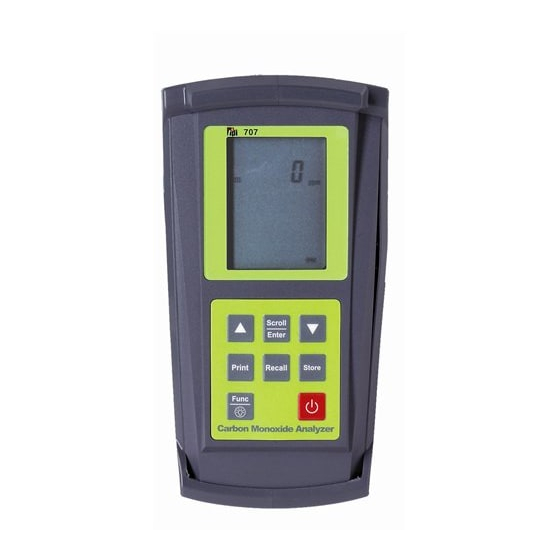
Instrument Overview Front View Rubber Boot Display Battery Condition Icon Keypad Rubber Boot Protects the instrument from accidental damage Display Large 3 Parameter Backlit LCD Display Battery Condition Icon Shows condition of batteries. Keypad Selects all available functions NOTE: When performing tests on oil fired equipment be sure to use the optional oil filter (A773) or readings could become erratic. -
Page 6: Keypad
Keypad Turns the 707 On (hold button in for 2 seconds) and Off Toggles between CO reading and Peak Reading. Used to Scroll Enter save, recall and print stored data. Used for setting date, time and accessing data storage addresses... -
Page 7: Back View
Back View Connection for Mini Pump Protection Filter Sample Inlet Calibration and Port Information Label Battery Compartment Sample Inlet Port: Connection for Gas Sampling Probe (see pages 7 & 11) Connection for Mini Pump Protection Filter (see pages 7 & 11) Calibration and Information Label: Displays calibration information and Displays serial number Battery Compartment:... -
Page 8: Side Views
Side Views Exhaust Port Infrared Window Rubber Boot Exhaust Port Port for connection of Exhaust Adapter Infrared Window Window for sending stored data to optional A740 IR Printer (see page 25 ) Rubber Boot Protects the instrument from accidental damage... -
Page 9: Top View
Top View Gas Sampling Port Gas Sample Port Connection for Mini Pump Protection Filter and Flue Probe (see pages 7 & 11) -
Page 10: Basic Analyzer Functions
After the 30 second countdown the instrument is ready to take carbon monoxide readings. The 707 will auto power off if no keys have been pressed for 10 minutes and the CO level is below 15ppm. Auto off can be disabled (see Appendix D). The... -
Page 11: Turning The Analyzer Off
Turning The Analyzer Off Always: - Before turning off return the instrument to a clean air environment and allow the Carbon Monoxide level to return to below 15ppm. Press the Power Key to turn the instrument off:- NOTE Should you attempt to turn the instrument Off and the CO reading is above 15ppm then the instrument will remain On and a short Beep will be heard. -
Page 12: Carbon Monoxidse Analysis Overview
Remember to consult with the manufac- turer of the device under test for specific test information. NOTE: Your 707 carbon monoxide analyzer is equipped with a high quality sensor that incorporates an on-board NO/NOx filter. This fil- ter prevents higher than normal CO readings caused by sensor cross sensitivity to NO/NOx, which is a byproduct of combustion. -
Page 13: Testing For Carbon Monoxide In Ambient Air
Please refer to Appendix A for general maintenance schedule and function tests. 1. Turn the 707 on in fresh air as outlined on page 8. After the initial purge cycle the 707 will display the screen below. -
Page 14: Acceptable Levels Of Co In Ambient Air
Carbon Monoxide in Ambient Air Chart This chart contains maximum exposure levels and times for carbon monoxide. This is a general guidline only. It is recommended you check with your local government for guidelines in your area. -
Page 15: Testing For Carbon Monoxide In Flues And Appliances
Please refer to Appendix A for general maintenance schedule and function tests. 1. Turn the 707 on in fresh air as outlined on page 8. After the initial purge cycle the 707 will display the screen below. - Page 16 3. For testing in a flue, drill a 1/4 inch hole into the flue of the device under test. For most applications, flue gas samples should be taken prior to the draft diverter or any other opening that allows room air to enter the system. This prevents room air from mixing with gases in the flue and diluting the test sample.
-
Page 17: Typical Test Locations
If necessary, drill a hole through the draft diverter to enable the flue probe to be inserted down into the fire tube. Cover the hole when the test is complete. The optional TPI flexible draft probe part num- ber A797 can be used without drilling a hole. - Page 18 TYPICAL TEST LOCATIONS Atmospheric Gas Fired Fan Assist Boiler / Furnace Typical Test Locations It is important to use manufacturers recommended test locations whenever possible.
- Page 19 TYPICAL TEST LOCATIONS Condensing Boiler / Furnace Typical Test Locations It is important to use manufacturers recommended test locations whenever possible.
- Page 20 TYPICAL TEST LOCATIONS Atmospheric Forced Air Furnace Typical Test Locations Test all exhaust ports at the top of the heat exchanger. It is important to use manufacturers recommended test locations whenever possible.
- Page 21 4. Insert the flue probe into the sample hole of the device under test. The probe tip should be in the middle of the flue pipe or exhaust stream. Ensure the In-Line Filter / Water Trap hangs below the analyzer in the proper vertical position when readings are being taken.
- Page 22 Monoxide (CO) in parts per million (ppm) NOTE: Your 707 carbon monoxide analyzer is equipped with a high quality sensor that incorporates an on-board NO/NOx filter. This fil- ter prevents higher than normal CO readings caused by sensor cross sensitivity to NO/NOx, which is a byproduct of combustion.
-
Page 23: Typical Test Results
Typical Test Results Actual test results vary depending on the equipment under test. TPI recommends you check with the manufacturer of the equipment being tested to determine specific acceptable results. Hot Water Heater Less than 50ppm Carbon Monoxide in the fire tube... -
Page 24: Setting Date & Time
SETTING DATE AND TIME With the analyzer running, press the Func Key to access the date/time screen. From this function Time, Date and Year can be changed. Function Display 4 (Date / Time) Time Date / Month Year If the Date and Time do not need to be changed, press the Func Key to bypass this function and return the 712 to combustion analyzer mode (Function 1). -
Page 25: Storing Data
STORING DATA During testing data can be stored for later retrieval. When data is saved, all data previously in the address will be overwrit- ten.When saving pressure/draft readings, select an address different from the one used to save combustion readings. 1. -
Page 26: Recalling Data
3. Using the up and down arrows, select the memory location of the readings you want to display. 4. Press the Scroll/Enter key once. The 707 will display the date and time screen showing when that reading was stored. 5. Use the up and down arrows to scroll through the data that was saved. -
Page 27: Printing Data
‘rEAL’ will be flashing. To cancel printing press the Print Key and use the Up/Down Arrow Keys to select “Yes” and press the Scroll/Enter Key. Selecting ‘rEAL’ will cause the 707 to print the test data currently on the display (real time data). Selecting ‘Stor’ will cause the 707 to print data stored in memory. -
Page 28: Printing Data
PRINTING DATA (Continued) Printout Interpretation Date and time of test. Data from test is print- ed here. Customer information and signed confirma- tion of test. (Fill in this data and have the customer sign for confirmation.) -
Page 29: Specifications
SPECIFICATIONS Instrument Operating Temperature Range 14°F to +122°F (-10°C to +50°C) Battery 1.5V AA size (3) Battery Life > 6 Hours Display Backlit LCD Data Storage 50 sets of readings Time & Date 24 Hour Real Time Clock Dimensions 200mm x 90mm x 60mm Weight 500g Casing... -
Page 30: Calibration & Service
**Sensor replacement requires calibration gas. WARRANTY Your TPI 707 Flue Gas Analyzer is guaranteed free from defects in materials and workmanship for 3 Years from the date of purchase. This guarantee does not affect your statuary rights. For additional information please refer to the included warranty card or contact TPI at 800-368-5719. -
Page 31: Appendix A General Maintenance & Function Tests
TPI analyzers use three filters to protect the pump and sensors. The first filter to check is the A763 mini pump protection filter. (see picture below) - Page 32 Appendix A: General Maintenance (continued) Filter Check Continued The other two filters are located in the water trap. The main filter is the A794F particle filter. This filter stops debris and dust from traveling down to the analyz- er. The secondary filter is the A794W water block filter. This filter stops flow in the event the water trap fills with condensate.
- Page 33 Appendix A: General Maintenance (continued) Flue Probe Integrity Check NOTE: Perform this check after performing the Pump Operation Check outlined on the previous page. 1. Turn the analyzer on as outlined on page 8. Do not connect anything to the inlet.
-
Page 34: Appendix B A773 Sulfur Filter Installation & Maintenance
Appendix B: A773 SULFUR FILTER INSTALLATION & MAINTENANCE When performing combustion tests on oil fired equipment it is important to use the optional A773 sulfur filter. Failure to do so can result in incorrect and readings. This filter also protects the sensors from the affects of sulfur. The A773 does not have to be removed when working with other types of fuels. - Page 35 Appendix B: A773 SULFUR FILTER INSTALLATION & MAINTENANCE 4. Beginning on the “Flue Probe” side of the A773 sulfur filter, pull the yellow thermocouple cord out of the channel of the flue probe tube. Pull out approx- imately the length of the water trap that was removed. 5.
-
Page 36: Appendix C Error Codes And Troubleshooting
Appendix C: ERROR CODES & TROUBLESHOOTING The 707 analyzer will display certain codes to let you know of a malfunction. Code Code Definition Possible Causes Corrective Action Displayed Pump not drawing sample at Blockage / kink in flue probe Check and rectify. -
Page 37: Appendix Dco Alarm & Auto Power Off
5. 707 Display: ‘0ppm’, ‘Co’, ‘rEF’. Action : Press the Func Key to bypass. 6. 707 Display: ‘2000’, ‘A-r’, ‘SEt’. Action : If you are not changing the CO alarm point press the Func Key. Otherwise press the Up and Down Keys to set the ppm level the alarm will sound at. -
Page 38: Appendix E Manually Initializing Sensors
7. 707 Display: ‘Auto’, ‘oFF’, ‘En’. Action : Press the Func Key to bypass. 8. 707 Display: ‘CAL’, ‘StoP’, ‘go’. Action : Press the Up Arrow Key to select ‘StoP’ by making it blink and press the Scroll/Enter Key to accept the selec- tion. -
Page 39: Appendix F Carbon Monoxide Facts
Appendix F: CARBON MONOXIDE FACTS Carbon Monoxide (CO) is invisible, odorless, and tasteless. It is the byproduct of combustion and levels are elevated when there is incomplete combustion. Sources of CO include: Unvented kerosene and gas space heaters Leaking chimneys & furnaces Gas water heaters Back drafting from furnaces Wood stoves&... -
Page 40: Appendix G Carbon Monoxide Limits In Ambient Air Chart
Appendix G: Carbon Monoxide in Ambient Air Chart This chart contains maximum exposure levels and times for carbon monoxide. This is a general guidline only. It is recommended you check with your local government for guidelines in your area. -
Page 41: Appendix H Battery Replacement
Appendix H: Battery Replacement When the battery status indicator is empty the batteries should be changed immediately. For optimum performance replace the batteries with 3 AA size alkaline batteries. The procedure for replacing batteries is as follows: 1. Turn the analyzer over and locate the phillips head battery cover screw. See picture below.
Need help?
Do you have a question about the 707 and is the answer not in the manual?
Questions and answers