Table of Contents
Advertisement
CONTENTS
1. Features ...................................................................................................................6
2. Precautions..................................................................................................................7
3. Nomenclature............................................................................................................ 9
4. Key functions.............................................................................................................11
5. Character entry............................................................................................................14
6. Display symbol............................................................................................................15
7. Mode Configuration....................................................................................................15
..............................................19
Unpacking and store of the instrument ..............................................................................19
1.
2. Setting the instrument up...............................................................................................19
3. Battery dismounting, information, recharging.......................................................................21
4. Reflector prisms........................................................................................................22
5. Mounting and dismounting the instrument from tribrach...........................................................22
6. Eyepiece adjustment and object setting...............................................................................23
7. Power on/off and preparation for measurement.......................................................................24
7.1 Power on/off..........................................................................................................24
7.2 Vertical Angle Tilt Correction .........................................................................................24
7.3 Display Illumination..................................................................................................26
7.4 Setting the Instrument Options........................................................................................26
7.5 Setting Instrument Constant..........................................................................................29
7.6 Setting LCD Contrast..................................................................................................30
7.7 Setting Date and Time..................................................................................................31
7.8 Explanations..........................................................................................................32
..................................................................33
....................................................................................33
8.1 Measuring the Horizontal Angle Between Two Points(Horizontal Angle 0)..................................33
8.1.1 Example Measuring the Horizontal Angle between Two Points..... ...........................................34
8.2 Setting the Horizontal Circle to a Required Value ..................................................................35
8.2.1 Use HSET function to set a required direction value ............................................................35
8.2.2Use HOLD to set a required direction value .......................................................................35
8.3 Horizontal Angle Display Selection(Right /Left) .................................................................36
8.4 Horizontal Angle Repetition ..........................................................................................37
8.5 Slope in %............................................................................................................39
...............................................................................39
9.1 Settings for Distance Measurement ................................................................................ ..40
9.2 Laser direction and laser plummet ..................................................................................42
1
Advertisement
Table of Contents

Related Manuals for Kolida KTS-442UT Series


Summary of Contents for Kolida KTS-442UT Series
-
Page 1: Table Of Contents
CONTENTS FOREWORD 1. Features ………………………………………………………..…………………………………………..6 2. Precautions……………………………………………...………………………………………………..7 3. Nomenclature……………………………………………………………………………………………... 9 4. Key functions……………………………..……………………………………………………………..11 5. Character entry……….…………….…………………………………………………………………..14 6. Display symbol………...………………………………………………………………………………..15 7. Mode Configuration……………………………………………………………………………………..15 PART 1 PREPARATION FOR MEASUREMENT ……………………………….………19 Unpacking and store of the instrument ……………………………………………………………….…..19 2. Setting the instrument up…………………………………………………………………………….…..19 3. - Page 2 9.3 Distance and Angle Measurement…………………………………………………………………….…..43 9.4 Review of Measured Data ……………………………………………………………………………..44 9.5 Output Data to a Computer……………………………………………………………………………..45 ……………………………………………………………..47 10. COORDINATE MEASUREMENT 10.1 Entering Instrument Station Data……………………………………………………………………..…49 10.1.1 Reading in Registered Coordinate Data………………………………………………………………..50 10.2 Azimuth Angle Setting………………………………………………………………………………….50 10.2.1 Set backsight point by Angle…………………………………………………………………………..51 10.2.2 Set backsight point by coordinate………………………………………………………………….…..51 10.3 Coordinate Measurement……………………………………………………………………………….52 PART 3 ADVANCED MEASUREMENT...
- Page 3 19.1.1 Define Horizontal Alignment (Maximum data quantity: 30)………………………………………...….95 19.1.2 Edit Alignment……………………………………………………………………………….……...100 19.1.3 Define Vertical Curve (Maximum 30 data)………… ……………………………… …………….…102 19.1.4 Edit Vertical Curve ……………………………………………………………………………….…103 19.1.5 Inport Horizontal Alignment…………………………………………………………………………105 19.1.6 Import Vertical curve……………………………………………………………………………..…106 19.1.7 Receiving Horizontal Alignment Data………………………………………………………..…….. .107 19.1.8 Receiving Vertical Curve Data………… …… ………… … ………………… ……………… …...109 19.1.9 Deleting Horizontal alignment Data ………...
- Page 4 20.3 Input Codes…………………………………………………………………………………..……….142 20.3.1Code import………………………………………………………………………………….……...143 20.3.2 Receive code……………………………………………………………………………..…….…..143 20.3.3 All clear ……………………………………………………………………………………………144 20.4 U disk mode ………………………………………………………………………………………….144 20.5 Initialization…………………………………………………………………………………….…….146 20.6 All Files ……….……………………………………………………………………….…….……….147 20.7 Setting for Grid Factor…………………………………………………………………………………148 ………………………………………………...….149 21. DATA RECORDING IN RECORD MODE 21.1 Recording Instrument Station Data………………………………………………………………...…...149 21.2 Recording backsight data…………………………………………………………………………..…..151 21.2.1 Set backsight point by Angle……………………………………………………………….………...151 21.2.2 Set backsight point by coordinate………………………………………………………….……...….152...
- Page 5 24.10 Parallel Between Collimation line and Emitting Photoelectric Axis……………………………………177 24.11 Reflectorless EDM………………………………………………………………………………178 24.12 Tribrach Leveling Screw……………………………………………………………………………..178 24.13 Related Parts for Reflector……………………………………………………………………………178 25. SPECIFICATION ..............................179 ………………………………………………………………………………..181 26. ERROR DISPLAYS …………………………………………………………………………….……..182 27. ACCESSORIES APPENDIX A BIDIRECTIONAL COMMUNICATION …………………………….183 ………………………………………………………………………….….182 1.1 Outputting Commands ………………………………………………………………………………..190 1.2 Entering Command ……………………………………………………………………………………….192...
-
Page 6: Foreword
Please read the manual book carefully before operating the instruments. 1. FEATURES 1. Complete Function KOLIDA KTS-442UT series has complete surveying program, the functions of data record and parameter setting, is suitable for professional and construction survey. 2. USD Pen Drive... -
Page 7: Precautions
11. If there is something wrong on the instrument, please do not disassemble the instrument unless you are a professional technician 12. Never aim the laser beam of KTS-442UT Series Total Station at human eyes. SAFETY GUIDE Interior EDM(Visible Laser)... - Page 8 Prevention: Do not stare at the laser beam, or point the laser beam to others’ eyes. Reflected laser beam is a valid measurement to the instrument. Warning: When the laser beam is shooting at prism, mirror, metal surface or window, the reflector laser beam is also harmful to eyes.
-
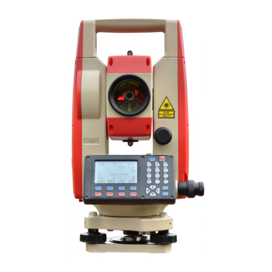
Page 9: Nomenclature
3. NOMENCLATURE Collimator Objective Lens Plate Level Screen USB Port Adjustment Screw for Circular Level... - Page 10 Eyepiece Battery Lock Telescope Grip Vertical Tangent Screw Battery Trigger Key Horizontal Tangent Screw Tribrach Circular Level Levelling Screw...
-
Page 11: Key Functions
4. KEY FUNCTIONS The KTS-442UT has a 28-keys keyboard. The keyboard has a power switch key, an illumination key, 4 soft keys, 10 operating keys and 12 alphanumeric keys. Backlight Power Enter Function Space Backspace Shift · Power ON :Press POWER. Power OFF :Press POWER for 3 seconds ·... - Page 12 Page 3 : Name Function Start missing line measurement RESEC Start resection measurement MENU Display menu mode Set the height of instrument and the target Operating Keys: Name Function Cancel previous operation and return to previous screen or mode. 1. Change page. 2. Enable target-height inputting in staking-out, missing line, and remote measurement.
- Page 13 · Hot Key 1. SP key: EDM Settings When you are not inputting numbers or alphabets, press SP key, a shortcut screen will be showed. Press ▲▼ key to move the cursor, press ◀▶ key to switch the setting. Press ENT to save the settings, press ESC to quit to upper menu.
-
Page 14: Character Entry
Trigger Key, to perform a fast measurement without moving your eyes away from eyepiece 5. CHARACTER ENTRY Job names, data numbers, codes, etc are entered to KTS-442UT using letters off the alphabet and numerals. Change between alphabetic and numerical entry by pressing SFT key. An S is displayed on the right side of the screen when in alphabet entry mode. -
Page 15: Display Symbol
6. DISPLAY SYMBOLS Some symbols are used in MEAS mode. Their meanings are presented below. Symbol Meaning Prism constant Atmospheric correction Zenith angle( Zenith 0° ) Vertical angle( horizontal 0° / horizontal 0° ± 90° ) % Slope in % Slope distance Horizontal distance Height difference... - Page 16 1. Quick guide (Measurement) Meas. (Record) 测量. PC -30 111.3742 m 测量. PC -30 JOB01 ↑ 92°36′25″ 7.Note 111.3742 m 120°30′10″ 8、查阅数据 JOB01 ↑ 1. Station data 92°36′25″ 111.3742 m HSET 2. Backsight data REC. 120°30′10″ 3. Angle data 92°36′25″ 0SET 4.
- Page 17 (1) MEAS mode menu Name Function SD (HD or VD) Distance measurement Select distance mode (Select between slope distance, horizontal distance, height difference) 0SET Set horizontal angle to 0 HSET Set known horizontal angle Select horizontal angle right/Left Horizontal angle repetition measurement HOLD Horizontal angle Hold/Release Switch between Zenith angle / slope in %...
- Page 18 Dist data Distance measurement data recording Coord data Coordinates measurement data recording Dist.and Coord. Record distance and coordinate data Note Note data recording View Review job data (3) Memory Mode Name Function JOB selection and management Known data Known data input and management Code Code input and management Define roads...
-
Page 19: Part 1 Preparation For Measurement
PART 1 PREPARATION FOR MEASUREMENT 1. UNPACKING AND STORE OF INSTRUMENT · Unpacking of instrument Place the case lightly with the cover upward, and unlock the case, take out the instrument. · Store of Instrument Cover the telescope well, place the instrument into the case with the vertical clamp screw and circular level upward (Objective lens toward tribrach), tighten the vertical clamp screw and lock the case. - Page 20 4. Leveling by the plate level ① Rotate the instrument horizontally by loosening the Horizontal Clamp Screw and place the plate level parallel with the line connecting leveling screw A and B, and then bring the bubble to the center of the plate level by turning the leveling screws A and B.
-
Page 21: Battery Dismounting, Information, Recharging
4) Use plate vial to level the instrument accurately. ①Rotate the instrument horizontally by loosening the Horizontal Clamp Screw and place the plate vial parallel to the line connecting leveling screw A and B, and then bring the bubble to the center of the plate vial by turning the leveling screws A and B. -
Page 22: Reflector Prisms
Unique Mini prism systems allows to be set up at corners that are hard to reach. Illustrated are the prism manufactured by KOLIDA: 5. MOUNTING AND DISMOUNTING INSTRUMENT FROM TRIBRACH Dismounting ·... -
Page 23: Eyepiece Adjustment And Object Setting
Mounting Insert three anchor jaws into holes in tribrach and line up the directing stub with the directing slot. Turn the locking knob about 180 degree clockwise and tighten the locking screw with a screwdriver. 6. EYEPIECE ADJUSTMENT AND OBJECT SETTING ·... -
Page 24: Power On/Off And Preparation For Measurement
7. POWER ON/OFF AND PREPARATION FOR MEASUREMENT 7.1 Power ON/OFF PROCEDURE · Power ON Operation Display Note After power on, instrument process self-check as Type: KTS-442UT left. S188888 Ver.: 21.10.10 Press POWER Finding USB……. Checking the inserted USB drive Meas. 111.374 m After Self-check, interface for measurement shows 92°36′25″... - Page 25 PROCEDURE Setting Tilt Correction Operating Procedure Operation Display MEAS. ⑴ Turn on the machine, enter MEAS screen. POWE 92°36′25″ 120°30′10″ HSET 2021-01-01 10:00:48 KTS-442UT No.S109996 ⑵ Press ESC to enter status screen. Ver.2020-1.02 File:JOB01 MEAS CNFG Config Obs. Condition Instr. Const ⑶...
-
Page 26: Display Illumination
Operation procedure Display Tilt sensor (1) If instrument tilts over correction range, system launch tilt correction function. X-ON XYON DIGIT (2)Leveling the instrument according to the related tilt sensor chapter until the black point centered in the circle X-ON: Only vertical angle be compensated XYON: Both horizontal and vertical angle are compensated X-ON... - Page 27 Screen Setting Parameter Options(*:Factory Setting) None * Atmospheric Correction K=0.14 K=0.2 Zenith 0 * Vertical angle format Horizontal 0 Horizontal 0± 90° None * Tilt correction 1- axis 2-axis Observation Slope distance * (Sdist) Condition Distance Mode Horizontal distance(Sdist) Height difference (Vdist) Auto Power Off Auto power off after 30 min * Switch ON/OFF by key...
- Page 28 Parity EVEN Stop bit 1bit * 2bits Check sum No * Transfer USB* Table 3 : Screen Setting Parameter Options(*:Factory Setting) ℃ Temperature ℉ hPa * Air Pressure mmHg Unit inchHg DEG * Angle Distance M (meters)* Ft (feet)
-
Page 29: Setting Instrument Constant
7.5 Setting Instrument Constant · Refer to “24.9 Instrument Constant (K)” to get the instrument constant value. Set it as following: PROCEDURE Operating Procedure Operation Display 设 Config 1. Obs. Condition 2. Instr. const 3. Date & time (1) From Status Mode Press CNFG to enter CNFG 4. -
Page 30: Setting Lcd Contrast
7.6 Setting LCD Contrast PROCEDURE Operating Procedure Operation Display 设 Config 1. Obs. Condition 2. Instr. const ⑴ 3. Date & time From Status Mode Press CNFG to enter 4. Comms setup config mode. CNFG 5. Unit 6.Key function “2. Instr. -
Page 31: Setting Date And Time
7.7 Setting Date and Time · It is possible to set or revise the date and time displayed in the “Status Screen”. PROCEDURE Operating procedure Operation Display 设 Config 1. Obs. Condition 2. Instr. const ⑴ 3. Date & time CNFG From Status Mode press CNFG to enter 4. -
Page 32: Explanations
7.8 Explanations Automatic tilt compensation When the “ ” symbol is shown on the display, the vertical angles is automatically compensated for small tilt errors using the tilt sensor. Meas. 92°36′25″ 120°30′10″ HSET Elimination of parallax Parallax is the relative displacement of the target image with respect to the reticle when the observer’s head is moved slightly up and down or to the sides while looking through the telescope. -
Page 33: Part 2 Basic Measurements
PART 2 BASIC MEASUREMENTS · This section explains the angle measurement, distance measurement, and coordinate measurement: which three can be performed in MEAS mode. · Measurement data can be recorded in the internal memory. For the recording method, refer to “21. Recording in Record Mode.”... -
Page 34: Example Measuring The Horizontal Angle Between Two Points
· To measure the included angle between two points, the horizontal angle can be set to 0 at any direction. PROCEDURE Operating Procedure Operation Display Meas. ⑴ Press FNC on the first page of the “MEAS Mode Screen”. 92°36′25″ Press 0SET, then 0SET flashes ON and OFF. 120°30′10″... -
Page 35: Setting The Horizontal Circle To A Required Value
Meas. ⑵ Sight the foresight point, the displayed Sight (HAR) value is the included angle between 2 Foresight 89°59′25″ points. Point 86°40′23″ OSET CRD. 8.2 Setting the Horizontal Circle to a Required Value 8.2.1 Use HSET function to set a required direction value ·... -
Page 36: Horizontal Angle Display Selection(Right /Left
(See “10.2Azimuth Angle Setting”) Direction angle calculation :BS 8.2.2 Use HOLD to set a required direction value · It is possible to use the horizontal angle hold function to set the horizontal angle of the sighting direction to a required angle. ·... -
Page 37: Horizontal Angle Repetition
PROCEDURE Operating Procedure Operation Display Allocate Meas. ⑴ In MEAS mode, display the screen in which [HAR] is registered. Horizontal angle display function 89°59′54″ becomes [HAR]. keys to 117°31′50″ display Meas. ⑵ Press R/L, horizontal angle display switches from [HAR] to [HAL]. 89°59′54″... - Page 38 PROCEDURE Operating Procedure Operation Display Repetition 0°00′00″ ⑴ In MEAS mode, press REP, Repetition BS Reps 0°00′00″ Sighting Screen is displayed. The horizontal 0° 00′00″ angle is 0. Sighting Take BS “Take BS” means to sight to backsight point. BS point Repetition 0°00′00″...
-
Page 39: Slope In
repeat step 4 and step 5. · When the repetition measurement is completed, press ESC. · In repetition measurement mode, even if “Automatic Tilt Compensation On” is selected, horizontal angle compensation will not occur. · Maximum measurement frequency :10 times ·... -
Page 40: Settings For Distance Measurement
Outputting the Data to a Computer Note: For KTS-442UT series Total Station, Measuring to strongly reflecting targets such as to traffic lights in infrared mode should be avoided. The measured distances may be wrong or inaccurate When the [MEASURE] key is triggered, the EDM measures the object which is in the beam path at that moment. - Page 41 velocity of the light in air is affected by the temperature and air pressure. Calculate the atmospheric correction factor as shown in following formula. If the unit is mmHg, please convert as: 1hPa = 0.75mmHg If the atmospheric correction is not required, set the ppm value to 0. ·...
-
Page 42: Laser Direction And Laser Plummet
After setting these, press ENT. · Setting method and content : Items Methods Temperature Methods 1: After entering temperature, pressure value, the atmospheric correction will be calculated automatically and PPM in 4 is displayed. Pressure Method 2: Directly entering the atmospheric correction factor (ppm), after Atmospheric correction PPM entry, the values for [Temp], [Press] are erased. -
Page 43: Distance And Angle Measurement
turn on Laser direction turn off Laser direction 2. Laser Plummet will automatically turn on after entering the interface. Press▲ or ▼: to adjust the brightness of laser plummet. Brightness value 0 : the centering device shut down. Brightness value 4 : the maximum value. -
Page 44: Review Of Measured Data
The result of repetition measurement is displayed: Dist. 1234.569 m 89°59′54″ 117°31′50″ STOP ⑶When distance measurement is completed, a During average measurement, the distance data is short beep sounds, and the measured distance displayed as S-1, S-2…… data (s), vertical angle (ZA), and horizontal angle (HAR) are displayed. -
Page 45: Output Data To A Computer
Allocation”. PROCEDURE Operating Procedure Operation Display MEAS. ⑴ In MEAS mode, display the screen in which 0.156 m [RCL] is registered, and press [RCL]. 34°45′09″ 126°31′23″ RCL (1) 0.156 m 34°45′09″ ⑵ The stored data which is most recently 126°31′23″ measured is displayed. - Page 46 PROCEDURE Operating Procedure Operation Display DOUT 1. Dist data ⑴In MEAS mode, display the screen in which 2. Angle data DOUT DOUT is registered, press DOUT, following screen is displayed. Dist. Select “1. ⑵ Use ▲▼ to select “1. Dist data,” and press Dist = -30 Dist data”...
-
Page 47: Coordinate Measurement
10. COORDINATE MEASUREMENT After inputting instrument height and target height, it is possible to find the 3-dimensional coordinates for the target based on station point coordinates and azimuth angle. It is possible to set the azimuth angle of a backsight station by entering the coordinates of the instrument station and a known point (backsight station) and then sighting at the backsight station. - Page 48 PROCEDURE Operating Procedure Operation Display Coord 1. Observation ⑴ Press CRD. in the second page of the CRD. 2. Stn data 3. Back sight data “MEAS mode screen”, or press MENU in MENU the third page, the Coordinate Measurement Menu Screen is displayed. N0 :...
-
Page 49: Entering Instrument Station Data
⑶ Press OK to read in the selected point and E : 1748.234 display the coordinate data. Z : 5121.579 Pt: LAST :View other data LAST TOP :View other data Press the key ESC to return to previous menu Code : KOLIDA LAST... -
Page 50: Azimuth Angle Setting
N0 : 1234.688 E0 : 1748.234 Z0 : 5121.579 ⑷ Press ENTER,the coordinate Measurement ENTER Inst. h : 1.600 m screen is displayed. Tgt. h : 2.000 m READ Coordinate measurement ⑸Press ok, display comes back to coordinate 1. Observation measurement screen. -
Page 51: Set Backsight Point By Angle
Input angle Set Azimuth ⑵ Input Azimuth and press OK key. value HAR: + Set Azimuth Sight BS point ⑶ Sight at backsight point and press YES. HAR: 120°00′00″ Record BS data Coordinate ⑷ Finish azimuth zetting and returns to coordinate 1. -
Page 52: Coordinate Measurement
Coordinate 1. Observation ⑷ Sight at backsight point, press YES, finish 2. Stn data setting and returns to coordinate measurement menu 3. Back sight data screen. NOTE: Read coordinate value from memory. Observation station coordinate value: Move the cursor to N0orE0orZ0 and press READ. Backsight station coordinate value: Move the cursor to NBS or EBS or ZBS and press READ. - Page 53 · Measurement data can be recorded in the JOB which has been selected. For the JOB selection method, see “20.1JOB selection”. · Check the following once more before measuring. 1. The KTS-442UT is set up correctly over the surveying point. 2.
- Page 54 F1 REC. Enter the following items: E : 1048.234 Z : 1121.579 1. Point name: target point number Pt. : KOLIDA 2. Code: Codes or notes. Ht : SA VE After each entry press ENT SA VE R.HT CODE...
-
Page 55: Part 3 Advanced Measurement
Coord. 1. Observation 2. Stn data ⑸ Press ESC to end and restore the 3. Set H angle “Coordinate Menu Screen.” ☆ When recording coordinate data, note that: The maximum entry length for point number is 14 characters. The maximum entry length for code is 16 characters. ☆... -
Page 56: Distance Setting-Out Measurement
11.1 Distance Setting-Out Measurement · The point can be found based on the horizontal angle from the reference direction and the distance from the instrument station. · From the menu mode, selecting “2. S-O” also can perform setting-out measurement. PROCEDURE Operating Procedure Operation Display... - Page 57 Np: 1223.455 Ep: 2445.670 ⑶ Select “2. S-O”, then press ENT, input Zp: 1209.747 Tgt. h: 1.620 m Select “2. following data: 1. Distance from the instrument Dist: 23.450 m station to the position to be set out. S-O” 45°12′08″ H ang:...
- Page 58 ⑺ Set the prism on the sight-line and sight it. PC = 0 Press HD to start distance setting-out measurement. Fine “ S” · Press SHV to select measurement mode. STOP ← → 0°00′00″ ⑻ When the observation is completed. The ↑...
-
Page 59: Rem Setting-Out Measurement
· Select setting-out measurement mode: Each time press SHV, setting-out measurement mode changes: SD → HD → VD → COORD → REM SD: slope distance setting-out measurement. HD: Horizontal distance setting-out measurement. VD: height difference setting-out measurement (the height difference between the instrument height mark and the center point of prism) COORD: coordinate setting-out measurement (refer to 11.3 Coordinate Setting-Out Measurement) REM: Remote setting-out measurement (refer to 11.2 REM setting-out measurement) - Page 60 Np: 1223.455 ⑷ Select “2. S-O data”, then press ENT, input Select “2. Ep: 2445.670 S-O data” following data: 1. prism height 2. the setting-out Zp: 1209.747 Tgt. h: 1.620 m point height (the distance from the surveying READ point to the point to be set out ) After each entry press ENT.
-
Page 61: Coordinates Setting-Out Measurement
← 1°00′00″ ⑼ Rotate the telescope up and down until the ↓ 0.000 value which displays on the second line is 0 m 80.123 m 89°45′23″ (As it nears 0 m, both arrows are displayed ), 150°16′54″ the point to be set out is now the center of the <-->... - Page 62 PROCEDURE Operating Procedure Operation Display Set-out Observation ⑴ Press S-O from the second page of the Set-out Stn Data MEAS mode, or from the MENU , the Back Sight Data “Setting-out Measurement menu screen” is displayed. Select “3. Stn data”, then press ENT (or ⑵...
-
Page 63: Distance Measurement Parameters Setting
SO. N 0.001 ⑹ Perform the procedure from the step 5 to step -0.006 10 in “11.1 Distance Setting-out Measurement” 5.321 150°16′54″ to find the point to be set out. To find the height 0°00′02″ CRD. of the point to be set out, press SHV to display <-->... - Page 64 1mmHg)or16.5 ~ 31.5inchHg (Foot length 0.1inchHg) Atmospheric correction PPM input range: -999 ~ +999 PPM (Foot length 1 PPM) Prism constant input range: -99mm ~ +99mm (Foot length 1mm) Reflector type:KTS-442UT series Total Station can be set visible laser distance measurement and unvisible...
-
Page 65: Offset Measurement
,The reflector includes prism,non-prism and reflector sheet. You can set by yourself according to your need. KTS-442UT series Total Station has the unvisible laser distance measurement function only, and the prism should match with the prism constant. -
Page 66: Single-Distance Offset Measurement
3. Dual distance offset measurement · Install the offset point A and B on a line extending from the target point, measure A and B, then enter the distance between B and the target point to find the target point. ·... - Page 67 PROCEDURE Operating Procedure Operation Display Dist Dist PC = 0 ⑴ Sight the offset point then press SD in the MEAS Mode Screen. Fine “S” STOP Meas. ⑵ When the measurement is completed, or 18.678 m during repeat measurement, press STOP, the 89°59′54″...
-
Page 68: Angle Offset Measurement
10.4 m ⑹ Press REC to record the results. Set the Pt.: following items while referring to “21.4 Code: KOLIDA Recording Distance Measurement data.” SA VE R.HT CODE Point number (Target point number) Code (press CODE to read in code) Input Tgt. - Page 69 PROCEDURE Operating Procedure Operation Display Dist Dist ⑴ Sight the target of the offset points and press Fine “S” SD in Meas mode. STOP Meas. ⑵ When observation is completed or after the measurement values are displayed during 11.678 m continuous measurement, press STOP to restore 59°39′54″...
- Page 70 Offset/Angle. 2.345 DIST ) 1.234 0.569 CRD. 10.29m 50.22m 10.4 m Pt.: Code: KOLIDA SA VE R.HT CODE ⑹ Press REC to record measurement result. (See “21.4 Recording Distance Measurement.”) Input Tgt. h Tgt.h: 0.000m Offset 1. Offset/Dist 2. Offset/Angle ⑺...
-
Page 71: Two-Distance Offset Measurement
12.3 Two-Distance Offset Measurement · Install two offset points (1 target and 2 target) on a straight line from the target point, observe the 1 target and target, then enter the distance between the 2 target and the target point to find the target point. ☆... - Page 72 Dist Dist PC = 0 ⑶ Sight prism 1, press OBS. to begin Fine “S” OBS. measurement. STOP Offset/2D 19.234 ⑷ When observation has been completed or 5.098 after the measurement values are displayed 1.234 during repeat measurement, press STOP to Sure ? display the “1 st Target Observation Result Screen.”...
-
Page 73: Missing Line Measurement
(10) 9.234 m 5.098m Press REC to input the Pt and code. 1.234m Press R.HT to input Target height. k2009 Code KOLIDA Press CODE to read in the recorded code in SA VE R.HT CODE memory. Offset 1. Offset/Dist 2. Offset/Angle 3. -
Page 74: Measuring The Distance Between Multiple Targets
· To find the height difference between 2 points, use a pole to make the target height of all the targets identical. 13.1 Measuring the Distance Between Multiple Targets · It is possible to perform Missing Line Measurement by selecting “4. MLM” from the Menu mode. 13.1.1 Measuring the distance between multiple targets Operating Procedure Operation... -
Page 75: Slope In Between 2 Points
⑶ When the measurement is completed, the “Missing Line Measurement Result Screen” is 20.757 m 27.345 m displayed. 1.020 m MLM S:Slope distance of the starting position 15.483 m 135°31′28″ and 2nd target. MOVE H: Horizontal distance of the starting position and 2nd target. -
Page 76: Changing The Starting Point
10.757 m 37.345 m 1.060 m ⑵ Press SD again, returns to the original screen. 15.483 m 70°24′18″ 135°31′28″ MOVE 13.2 Changing the Starting Point · It is possible to change the last measured point to the next starting point. PROCEDURE Operating Procedure Operation... -
Page 77: Rem Measurement
⑶ Press YES, the last target measured becomes the new starting position. Refer to “13.1.1 15.483 m Measuring the Distance Between Multiple 70°24′18″ Targets”, perform missing line measurement of 135°31′28″ the next target point. MOVE 14. REM MEASUREMENT · An REM measurement is a function used to measure the height to a point where a target can not be directly installed, for example a power cable, bridge, etc. - Page 78 PROCEDURE Operating Procedure Operation Display ⑴ Set the prism directly under or directly over Height Tgt.h. : 1.650 m the object and measure the target height with a Inst. h. : 2.000 m tape measure. Press HT on the third page of “MEAS Mode Screen”.
-
Page 79: Resection Measurement
Meas. ⑹ Press ESC to return to the measurement 11.678 m mode screen. 59°39′54″ Maximum angle of measurement possible: ± 89° 90°01′00″ Max. measurement distance (Ht.): ± 9999.999 m Note: To change target height, press FNC key 15. RESECTION MEASUREMENT ·... - Page 80 · It is possible to read in a coordinate data registered in advance. · It is possible to record set known point coordinate data or calculated instrument station data in the JOB which has been selected. For the JOB selection method, see “16.1 JOB Selection”. ·...
- Page 81 ⑸ When the measurements are completed, or Resection Point: when STOP is pressed after the measurement 6.979 m values are displayed during repeat measurement. 99° 31′28″ · When ANG has been selected, the distance can 67° 11′15″ not be displayed. :...
-
Page 82: Re-Observing
15.1 Re-Observing · It is possible to perform re-measuring from the first known point or only the last known point. PROCEDURE Operating Procedure Operation Display Re-OBS 1. Start point 2. Last point ⑴ In the “Resection Result Screen,” press ROBS ROBS. -
Page 83: Area Calculation
☆When there is a known point not yet measured; perform measurement using the same procedure beginning with step 3 in “Chapter 15. Resection Measurement.” ☆When a known point is to be added, perform measurement using the same procedure beginning with step 1 and 2 in “Chapter 15. - Page 84 P3 (N3, E3) P4 (N4, E4) P5 (N5, E5) · Number of specified coordinate points: 3~20 · Area is calculated by observing the points on a line enclosing an area in order or reading in the previously registered coordinates in order. ※NOTE: ·...
- Page 85 01: ⑵ 02: Every point use during calculation can be gotten 03: by measuring or reading from memory. Sight 04: 05: Point 1 READ OBS. For example Measuring point 1: OBS. Sight the first point on the line enclosing the area and press OBS.
-
Page 86: Setting Out Line
⑹ Move the cursor to the third point, if the 01:pt_01 coordinates is gotten by measuring, it displays 02: 6 “pt_03”. If the coordinates is read from memory, 03:pt_03 it displays the point number. (For example: 6) 04: 05: When known points amount is enough to be used READ CALC MEAS... -
Page 87: Defining Baseline
17.1 Defining Baseline You need to define the base line before setting out straight line. You can define a baseline by inputting two points’ coordinates. The scale factor value is the difference between the input coordinate and the observed coordinate. ·... - Page 88 (3)Select “1. Stn data.” The station data can be 0.000 manually input or read in by pressing READ key 0.000 and pressOK, return to the “Set-Out Line screen.” Stn data 0.000 Inst.h: 0.000mm Then set Backsight Data. Backsight Tgt.h: 0.000mm Data READ (4)...
-
Page 89: Set-Out Line (Point)
17.2 Setting-out Line (Point) Setting-out line point measurement can be used to find the required point coordinate by inputting the length and offset based on the baseline. · Before performing setting-out line point, the baseline must be defined. Procedure Display set out line (1) After set Station Point, Backsight Point, define baseline, point... -
Page 90: Seting Out Line (Line)
Set out line (PT) Press F4 OK. The coordinate value of the required point is 2705201.124 calculated and displayed. 121144.997 (to enter the second page, press F4 P1). 89.297 · REC: records the coordinate value as a known point data. (Refer to “21. - Page 91 Display Procedure (1) After set Station Point, Backsight Point, set out line define baseline, Select “5. Line” in the 1. Stn data “Set-Out Line Menu. 2. back sight data 5.line 3. define baseline 4. point 5. line (2) Enter the offset value and press F4 OBS Set-out line ( L) Enter length and offset Offset: How much to move the baseline.
-
Page 92: Point Projection
Set-out line ( L) ⑸ Sight at the next target and press OBS to Sight the next target + 2.219m continue the measurement. · Press REC to record the measurement results. 1.115m -0.097m 27 43’ 58” R. HT 18. Point projection Point projection is used for projecting a point onto the baseline. -
Page 93: Point Projection
Point projection Select PROJ, the Point Projection PROJ Stn data menu is shown. back sight data define baseline point projection Define base line(1) 236 18’35” Input the Station and backsight data and difine the base line. Hcalc: 3.606 m Hmeas: 3.606 m Please take “17.1 define baseline “as a P1↓... - Page 94 Point projection Coord. Point 0.0000 m 0.0000 m 0.000 m READ MEAS Point projection (3) Enter the point coordinate. Coord. Point · Press MEAS to measure the coordinate. 2705195.064 m · When recording the coordinate data, press REC. 121139.542 m 91.678 m READ MEAS...
-
Page 95: Road Design And Setting-Out
Point projection Coord. Point Press ESC, repeat steps from step 3. 1.686 m 1.128 m -1.132 m READ MEAS Note: It is possible that you don’t have known point coordinates to set station and backsight point. You can assume a Station Point coordinate, input angle to set backsight point. Then measure the start point and end point to get their coordinates, use them when you are designing baseline. - Page 96 Roads 1. Define Roads 2. Set-Out Roads ⑵ Slect “1. Define Roads” in the “Roads Menu” Select“1.Define and select “1. Define HZ AL.” HZ AL” Roads(1) 1. Define HZ AL 2. Edit HZ AL 3. Define VT AL 4. Edit VT AL 5.
- Page 97 Operating Procedure Operation Display Define HZ AL Chain: 1000.000 ⑴ Press STR key in the “Input Process Screen”, 0°00′00″ the “Define Straight Screen”. TRNS Straight Enter bearing 0.0000 ⑵Enter the bearing of straight line, press ENT Distance: 0.000 m key to access next entry option, after straight Enter length, press ENT key.
- Page 98 Enter radius and Radius: 0.000 m ⑵ Enter radius and arc length, then press ENT Arc length 0.000 m arc length to record this data. Define HZ AL Chain: 1020.000 75°37′11″ ⑶ PressOK to record the alignment data. TRNS Transition curve Press TRNS key in the “Main Line Input Screen”, the transition curve can be defined.
- Page 99 Transition Enter the minimum Radius: 0.000 m ⑵ Enter the minimum radius and Spiral length Spiral length: 0.000 m radius and of transition curve, and press ENT. arc length Define HZ ZL ⑶ Chain: 1028.000 Press OK to record the data and restore the 83°15′32″...
-
Page 100: Edit Alignment
: 0.000 m : 0.000 m enter N, E ⑵ It allows to enter N, E coordinate, radius and : 0.000 m A1, A2 manually, and press ENT. Or press coordinate, A1 : 0.000 READ to read in the coordinates stored in A2 :... - Page 101 Start Point CH : 1046.000 : 201.000 m ⑵ The first alignment data in memory is : 102.000 m displayed. READ NEXT LAST SRCH Straight 48.3000 ⑶ Press NEXT to find the alignment data to be Distance: 56.678 m edited. PREV NEXT SRCH...
-
Page 102: Define Vertical Curve (Maximum 30 Data)
⑶ Search alignment Invalid chainage! If the entered chainage is not existed in memory, an error message will be displayed. After several seconds, it restores previous screen which SRCH is displayed. Start Point CH : 1046.000 : 200.000 m : 100.000 m B:... -
Page 103: Edit Vertical Curve
Chainage 1000 1300 1800 2300 Elevation Curve length Intersection points can be entered in any order. After entering a point data, press ENT to save it and go to enter next one. Press ESC to exit without saving. PROCEDURE Operating Procedure Operation Display Roads(1) - Page 104 Edit VT AL CH.: 1000.000 Elevation: 50.000 m Len.: 0.000 m (2)The first curve data in memory is displayed. PREV NEXT SRCH STRT READ Edit VT AL CH: 1106.000 Elevation: 200.000 m ⑶ Press PREV or NEXT to find the required Len.:...
-
Page 105: Inport Horizontal Alignment
⑶ A: Search alignment If the entered chainage is not existed in memory, Invalid chainage! the first vertical curve data will be displayed. B: Edit VT AL CH.: 1100.000 Elevation: 50.000 m If the entered chainage is existed in memory, Len.:... -
Page 106: Import Vertical Curve
overwrite it or not. HZ AL Import YES : start importing NO : Exit Overwrite File? (4) After transmission it returns into “Define Import HZ AL Road “menu. From : B: \ 2. TXT To: : A:\ JOB1. HAL EXIT Finishing 19.1.6 Import the Vertical curve (vertical alignment) The princelpe is same to the last chapter. -
Page 107: Receiving Horizontal Alignment Data
VT AL Import From : B: \ 2. TXT To: : A:\ JOB1. VCL EXIT 19.1.7 Receiving Horizontal Alignment Data The horizontal alignment can be transferred from computer to instrument by using alignment elements. The default definition should be included. The default definition consists of the start chainage and the point’s coordinate. Alignment element consists of point, straight line, arc and transition curve. - Page 108 parameters setting. To transfer data from computer, you should have corresponding program, the required format for data can be provided by the software, and the data can be sent in any parameter method. PROCEDURE Operating Procedure Operation Display Define road(1) 1 define HZ A L 2 Edit HZ AL...
-
Page 109: Receiving Vertical Curve Data
19.1.8 Receiving Vertical Curve Data The vertical curve data can be transferred from computer to instrument by using character point and chainage. The vertical curve data shoud consists of elevation, curve length. The start and end curve length should be 0. Data format: Chainage, elevation, length For example:... -
Page 110: Deleting Horizontal Alignment Data
Receive VT AL ⑷Start receiving. To stop receiving, press STOP. Tansfer : JOB: A:\ JOB1. VCL Receiving STOP 19.1.9 Deleting Horizontal alignment Data The alignment data in memory can be deleted. PROCEDURE Operating Procedure Operation Display Define road(2) 6 VT AL Import (1) Select “9. -
Page 111: Road Setting-Out
⑵When “Vertical curve delete?” is displayed, press YES, the data will be deleted, the screen VT Alignment restore the Roads screen. Delete? To exit, press NO. 19.2 Road Setting-out It is possible to perform alignment setting-out for the designated point by using the chainage and offset which is ensured in road design. -
Page 112: Set Station Point
19-2 19.2.1 Set Station Point It allows you to set station point by reading from memory (N, E, Z coordinate) or entering manually by keyboard (chainage and offset). PROCEDURE Operating Procedure Operation Display Roads 1. Define Roads 2. Set-Out Roads ⑴... -
Page 113: Setting Backsight Point
⑷ A: A: N0: 1000.000 The point coordinate is calculated on the basis E0: 1000.000 of the entered chainage and offset. Z0: 0.000 m It the vertical curve data of the chainage is 100.000 existed in memory, the elevation of the point Inst. - Page 114 Set Azimuth Enter HAR:0.0000 bearing (2)Enter the bearing angle and press OK. angle Set Azimuth Sight BS Point (3) Press YES to record the data 0° 00’ 00” NO YES Set out roads 1. Stn data Angle ⑶ PressOK, the screen restore the “Set Out Coord Roads Screen.”...
- Page 115 A: ⑶ Set Back Sight Pt A: Enter the chainage, offset of the backsight Chain 1000.000 Enter the point. Offs. 20.000 m chainage, offset READ B: Read data B: To read in coordinate data from memory, READ pressREAD. Crd. 4 ↓...
-
Page 116: Setting Out
Set out roads 1. Stn data (6) Return to set-out road s menu. angle coord Set Out 19.2.3 Setting Out After Setting station point and backsight point, it is possible to perform Setting Out measurement. PROCEDURE Operating Procedure Operation Display Set out roads 1.... - Page 117 ⑷ Press LOFS(orROFS) to set out the left (or Alignment Setout right) side stake, the corresponding chainage, offset, height difference will be displayed in Chain: 1000.000 the screen. Offs: -2.150 It is possible to enter the chainage and offset HtDi: -0.150 manually.
- Page 118 ⑻ Press <--> then press CRD. To display the “SetOut guide screen.” Set Out The angle value which displays on the seond ← -36°13′46″ line is the difference of the measured angle <--> ↓ value and the required set-out value. The -7.882 ↑...
- Page 119 sighting the prism.) ↓ : Move the prism to the station point direction. ↑ : Move the prism away to the station positon. Set Out ⑿ Press CRD., move the prism up or down to ← → 0°00′00″ ↑ ↓ make the displayed height difference value to 0.000 be 0 m(When the value is near to 0 m, there...
-
Page 120: Slope Setout
of the left side stake. ROFS: The key is use in setting out the right side stake. Press it to display the offset and the height difference of the right side stake. +CHG: The key is use in increasing the chainage. -CHG: The key is use in discreasing the chainage. - Page 121 PROCEDURE Operating Procedure Operation Display Alignment Setout Chain: 1000.000 ⑴ Press SLOPE in the screen of alignment SLOPE Offset: -2.150 setting-out chainage and offset. HT. Diff: -0.150 Tgt.H : 2.000 m LOFS ROFS +CHG SLOPE Slope Setout (1:N) Input slope Cut L :...
-
Page 122: Setting-Out Arc
⑸ Setout Sight the point that to be intercepted near the slope, press MEAS to start slope setting-out. It Setout PSM = 0 PPM = 0 chooses proper slope from the data input in Fine “S” previews PROCEDURE. Supposes the height STOP of target point is level benchmark, and calculate the point to be intercepted. - Page 123 Start Point 2500454.737 484135.308 End Point 2500461.017 484123.613 Verification Point (arc length 3m) 2500454.789 484132.318 Radius of the Arc 11.707 m Operating Procedure Operation Display Menu (2) 6. Resection Choose 10. 7. Repetition ⑴ Choose “10. Setting-out arc” in the 2 page Setting-out 8.
- Page 124 Input End pt SPN: 2500461.017 Coord. (4) Input end point coordinate then press F4 OK. SPE: 484123.613 It goes to Radius input screen. + F4 SPZ: 0.000 READ Input arc r (5) Input Arc Radius then press F4 OK. Input Arc r:...
- Page 125 Offset can be positive or negative. Under the designed coordinate system: If the setout point is on the direction from “center of the circle” to the “Arc Length Point”, Offset value is positive. If the setout point is on the negative direction of above, Offset value should be negative.
-
Page 126: Part 4 Data Recording
PART 4 DATA RECORDING · This section explains JOB or memory settings which can be performed in Memory Mode and data recording methods which can be performed in Record Mode. · Press MEM in Date/ time Screen to enter Memory Storage screen. Memory Mode Screen ↑... -
Page 127: Setting In Memory Mode
20 SETTING IN MEMORY MODE · To enter Memory Mode, press MEM in the “Status Memory Mode Screen Screen” · In Memory Mode, it is possible to perform settings ↑ Memory concerning JOB and memory. 1. JOB 2. Known data ·... -
Page 128: Check Memory Status
(3) imput the file name then press F4 OK. JOB selection Job : J0B2 ▲ Or press F1 LIST to choose an existed job. Press ▼ ENT to confirm LIST * JOB01 [JOB] Note: when you input file name, press SFT to List * JOB02 [JOB]... -
Page 129: 3Create New Working Job
Disk:A Filer : check the disk space ATTR to Type: local disk File Sys: FAT 12 Used spc: 0.04 return to previous menu ESC to Disk:A Free spc: 1.96 MB Capacity:: 2.00 MB Format Disk :B Enter the interface for FORMAT formatting Format may del data... -
Page 130: Change The Job Name
JOB1.JOB [JOB] Press P2 to enter the second JOB2.JOB [JOB] page. Press NEW to create new list. ATTR SRCH EXIT REN. Select “2 New job” to create New direct new file New job OK Finish the creation for new job and return to previous menu. New job Dir.: The user can create new job in... -
Page 131: Delect Job
REN. Press REN. to enter the screen for changing job name. JOB: JOB1 OK Finish the operation and return to previous menu 20.1.5 Delete Job This function is to clear the data in working job. If the data in JOB file was deleted, the filename which have been changed will restore to its default name automatically. -
Page 132: Coordinate Selection
20.1.6 Coordinate Selection Coordinates can be selected through below operation. PROCEDURE Operating Procedure Operation Display Mem./ JOB (1) JOB selection ⑴ Select “1. JOB” in the “Memory Mode “1. JOB” Coord. read JOB Screen” and press ENT (or press numeric key 1), JOB Export Coord. - Page 133 PROCEDURE Operating Procedure Operation Display Mem./ JOB (1) JOB selection ⑴ Select “1. JOB” in the “Memory Mode “1. JOB” Coord. read JOB JOB Export Screen” and press ENT (or press numeric key 1), Coord. import the “JOB Management Screen” is displayed. Comms Output Insert a USB pen drive to total station USB port.
-
Page 134: Coordinate Import
20.1.8 Coordinate Import It is to transfer coordinate data from USB pen drive to total station memory. It is not allowed to transfer between two jobs which are all exisited in Local disk. PROCEDURE Operating Procedure Operation Display ⑴ Select “1. JOB” in the “Memory Mode Mem./ JOB (1) JOB selection Screen”... -
Page 135: Comms Output
* 2. You can edit data by Microsoft Office (Excel) , then save as .CSV format. File name can be with number and alphabet. 20.1.9 Comms output It allows to output working jobs from instrument to computer. PROCEDURE Operating Procedure Operation Display Mem./ JOB (1) -
Page 136: Comms Input
It allows user to transfer data from computer to total station and restore it in working jobs. First, edit the coordinate data by KOLIDA data transmission software in the computer Second, set the data communication parameters in total station and computer. -
Page 137: Transfer Coord Data To Job
Comms input Transfer: USB Job: A \ job. Job (3)Choose the job name and press ENT to start Receiving input. STOP Mem./ JOB (2) Comms input (4)Finish the imputting and return to previous 2. Key in Coord. menu 20.1.11 Transfer coord data to job User can imput coordinate data into working job. -
Page 138: Import Known Point Data
0.000 m (5)Input the coordinates value N E Z, point name, 0.000 m and code. 0.000 m Pt.: Code: KOLIDA REC. CODE (6)After finish the imput, press REC. to record 100.000 m the known point. 10.000 m 1.000 m Press ESC to return to previous menu. -
Page 139: Known Coordinate Data Import
“Coordinate Data Entry Screen” is displayed. coord” 10.000m Pt.: Press ADD to set the following items: Code: KOLIDA N, E, Z coordinate values, point name, code. After each entry press ENT. ⑷ 1. Key in coord Press REC to record the coordinate value 2. -
Page 140: Known Coordinate Data Export
N coordinate E coordinate Z coordinate 2. The coordinate format which is provided by KOLIDA software. Point number, ,E,N,Z CRLF First, edit coordinate format with KOLIDA communication software on computer. · Second, set communication parameters on total station.(Refer to “23.1Changing Instrument Parameters”)... -
Page 141: Sending Known Point Data To Computer
Operating Procedure Operation Display 1. Key in coord 2. coord import ⑴ Select “2. Known data” in the “Memory “2. Known 3. coord export data” Mode Screen” and press ENT to show the 4. comms input 5. comms output “Known Point Menu Screen”. 6. -
Page 142: Clearing Coordinate Data From Memory
20.2.6 Clearing Coordinate Data from Memory This operation is for deleting all coordinate data in internal memory. Operation Procedure Display 1. Key in coord 2. coord import “2. Known ⑴ Under memory mode choose “2. Known 3. coord export data” data”and press ENT to enter known point screen. -
Page 143: 1Code Import
Mem./Code ADD to input code 1. Key in code OK to record the code. 2. Code import 3. receive code ESC to finish inputing 4. Clear list The max. length is 16 characters 20.3.1 Code import PROCEDURE Operating Procedure Operation Display Mem./Code 1. -
Page 144: All Clear
Receive code (3)When the transfer is finished. The screen Transfer:USB return back to previous menu automatically Job:A:|\ PCDDE. LIB Receiving STOP 20.3.3 All clear All code data in memory can be deleted by this operation PROCEDURE Operating Procedure Operation Display Mem./Code “3. - Page 145 Disk Mode (2)Enter the display for connecting Connected to PC…………. EXIT (3)Double click “my computer”, you see the local disk I (total station) and mobile disk H (SD card). (4)Double click local disk I or removable dick H, then choose the file data that you want to edit, right click it and select the “copy command”...
-
Page 146: Initialization
20.5 Initialization · This operation restores instrument parameters to factory default settings and clear all data. · Below settings will be restored by initialization. ① Observation condition: Atmosphere correction, vertical angle format, tilt correction, measurement type, auto power off, coordinate unit, minimim angle display, minimum distance display, keyboard buzzer, same (or different) result of coordinate measurement by measuring with face left/ right. -
Page 147: All Files
Operating Procedure Operation Display Memory (1) 1. JOB ⑴ Select “6. initialize “and press ENT (or “6.initialize” 2. known data 3. code press numeric key 6), 4. define roads 5. U disck mode Memory (2) 6. initialize 7. all file 8. -
Page 148: Setting For Grid Factor
(3)Show file list PCODE. LIB code fixed file PCODE. LIB [CODE] COORD. PTS known data COORD. PTS [Know] Those two files are system file , which could not JOB1.JOB [JOB] be deleted or changed. JOB1.HAL [HZAL] JOB1.JOB job file JOB1.JVCL [VTAL] JOB1.HAL horizontal alignment file... -
Page 149: Data Recording In Record Mode
Operation procedure Display Memory (1) 1. JOB (1)Select “8. Grid factor” in Memory Mode 2. known data Screen” and press ENT (or press numeric key 8). 3. code “8. Grid factor” 4. define roads 5. U disck mode Memory (2) 6. - Page 150 date, time, weather, wind, temperature, air pressure, atmospheric correction factor, target type, prism constant correction value, and distance measurement method. PROCEDURE Operating Procedure Operation Display 1. Stn data A:\JOB01 2. back sight data ⑴ Press REC in the second page of MEAS 3.
-
Page 151: Recording Backsight Data
· Movement of the cursor between items:▲ ▼ · Entry rules: Read in coordinate:READ Pt. :14 numerals and letters Code: 16 numerals and letters Read in code:CODE Time:pm 3:33:37 enter 153337 Date:Year 2010 month 8 day 7 enter 20100807 · Setting methods and content: Weather:Press to select (clear, cloudy, light rain, rain, snow) Wind:Press... -
Page 152: Set Backsight Point By Coordinate
1.Stn data A:\JOB01 2. back sight data 3. angle data ⑷ Finish azimuth z ettingand returns to previous 4. dist data menu 5. Coord data 6. dist+ coord data 21.2.2 Set backsight point by coordinate You can set backsight azimuth angle by inputting backsight coordinate, the machine calculates azimuth angle by station point coordinate and backsight coordinate. - Page 153 *HAR 64°22′10″ Pt. : Set the following items: point number, code, k2009 target height. Code: KOLIDA After each entry press ENT. Tgt. h: 1.67 m · Maximum point number size: 14(alphanumeric) SA VE CODE · Maximum code size: 16 (alphanumeric) REC/Angle ⑸...
-
Page 154: Recording Distance Measurement Data
1. Stn data A:\JOB01 2. back sight data 3. angle data 4. dist data ⑺ Press ESC to restore the “Record Mode 5. Coord data Screen.” 6. dist+ coord data · · Perform distance measurement to record automatically by pressing a single key: AUTO. When this key is used, it is unnecessary to perform distance measurement in MEAS Mode. - Page 155 · KTS automatically increments the last input number by 1 and Pt. : 2000 display it. This point number can be used to record data in the code kolida memory or can be changed. SA VE R.HT CODE · Codes registered in advance can be read in by pressing CODE REC/Dist.
-
Page 156: Recording Coordinates Data
⑷ Press REC to record the measurement data 49.098 Pt. : with *. POINT2000 Enter following data: Point number, code, target Code: KOLIDA height. SA VE R.HT CODE ⑷ REC/Coord. When the self checking is finished, Press SA VE to record data. System will creates a new point number by adding “1”... -
Page 157: Recording Distance And Coordinate Data
Coordinates Coord. ⑹ Press OBS to measure the coordinates again Fine “S” OBS. in Record Mode. STOP 1. Stn data A:\JOB01 2. back sight data 3. angle data ⑺ Press ESC to restore the “Record Mode 4. dist data Screen.” 5. -
Page 158: Recording Notes
⑵ Press F4 AUTO , the screen shows as right Dist+ Coord 1201 rec 100.364 diagram, the line 2,3,4 (with“*”) are measured data. 234.897 AUTO System will creates a new point number by adding 49.098 “1” on the base of last point number. user can use Pt.:... -
Page 159: Reviewing Job Data
REC./Note ⑵ Select “7. Note” and press ENT (or press KOLIDA “7. Note” numeric key 7), the “Note Entry Screen” is displayed and the final note data prepared is displayed. SA VE 7. note (3) Enter the note and press SA VE to restore the 8. - Page 160 Pt 101 Pt 102 Pt 103 ⑷ Press ESC to return to previous menu Pt 104 VIEW SRCH DEL 7. note 8. view ⑸ Press ESC again to restore the “Record Mode Screen.”...
-
Page 161: Part 5 Measurement Options Selection
PART 5 MEASUREMENT OPTIONS SELECTION · This section explains the setting of keys functions of KTS-442UT, the setting of parameters, etc. 22. KEY FUNCTION ALLOCATION · With the KTS-442UT, it is possible to allocate the soft keys in MEAS Mode to meet measurement conditions. The current soft key allocations are retained forever until they are revised again, even when the power is cut off. -
Page 162: Allocation And Registration
Existing Key Allocations 1. Setting 2. Registration Set new allocations in Key Allocation Mode RECORDING Registration Display new key allocations Call Out 3. Read in 22.1 Allocation and Registration · It is possible to set new key allocations in the “Key Allocation Screen.” When new key allocations are set, the content of the function keys in MEAS Mode are displayed. -
Page 163: Allocating Functions
It is possible to allocate the functions displayed in the “Setting Mode Screen” to the soft keys. The following functions can be allocated to the soft keys. 1) SD, HD, VD: Distance measurement. 2) SHV: Select distance mode (slope distance, horizontal distance, height difference) 3) 0set: Set horizontal angle to 0 4) H. - Page 164 one key on the same page (example 2). And it is also possible to allocate a function to only one key (example 3). Example 1 DIST, SHV, H. ANG, EDM DIST, SHV, H. ANG, EDM Example 2 DIST, SHV, H. ANG,, DIST -------------------------------- Example 3 DIST, SHV, ----, ----...
-
Page 165: Registering An Allocation
↑ P1 DIST DIST HSET P2 0SET HOLD 0SET ⑸ Press ENT to allocate the functions HSET designated in step 4 to the positions designated in P3 MLM RESE step 3. MENU Key Func. 1. Define ⑹ Repeat steps 3 to 5 only as many times as 2. -
Page 166: Recalling An Allocation
22.2 Recalling an Allocation · It is possible to recall the soft key arrays registered for User 1 and User 2 as necessary. NOTE: When an array is recalled, the key array is changed to the key array which has been recalled, clearing the previous key array. - Page 167 Vertical angle format Horizontal 0° Horizontal 0° ± 90° None* Tilt correction Dual-axis Single axis OBSERVATION SD * CONDITION Distance measurement mode Automatic power cut off Auto cut off after 30 Minutes * Switch on/off by key Coordinates format N-E-Z * E-N-Z 1″...
- Page 168 Table 3: Screen Setting Parameters Option(*:Factory setting) ℃ * Temperature ℉ hPa * Air pressure mmHg Unit inHg DEG *(360 degrees) Angle GON (400 gons) Distance PROCEDURE Operating Procedure Operation Display 2020-01-01 10:00:48 KTS-442UT No.S19996 ⑴ In Measurement screen, press ESC to show Ver.2020-1.02 the status screen.
- Page 169 Config (1). 1. Obs. condition 2. Instr. const ⑷ Align the cursor with the final item after 3. Date & time 4. Comms setup setting is complete and press ENT. The “Setting Mode Screen” is displayed. 5. Unit Baud rate: 1200b/s ⑸Select “4.
-
Page 170: Part 6 Checking And Adjustment
PART 6 CHECKING AND ADJUSTMENT The instrument has been checked and adjusted strictly in the factory and can meet the quality requirement. But the long distance transportation and the change of the environment will have great influence on internal structure of the instrument. -
Page 171: Inclination Of Reticle
24.3 Inclination of Reticle · Inspection 1. Aim at object A through the telescope and lock the horizontal and vertical clamp screws. 2. Move object A to the edge of the field of view with the vertical tangent screw (point A′) 3. - Page 172 2C=L-R± 180° =-30″≥±20″, adjustment is necessary. · Adjustment A:Adjustment by on-board program: Operation procedure Display 2020-09-10 10:00:48 ⑴ After levelling the machine, power on, press Type:KTS-442UT CNFG under date/ time screen, as right diagram No. :S112926 shows. CNFG Ver.:20.09.10 Job :JOB01 MEAS MEM CNFG “2.
-
Page 173: Vertical Index Difference Compensation
Optical adjustment (Only for professional service technician) B: 1. Use the tangent screw to adjust the horizontal angle reading, 2. Take off the cover of the reticle between the eyepiece and focusing screw. Adjust the two adjusting screws by loosening one and tightening the other. Move the reticle to aim at object A exactly. - Page 174 2020-09-10 10:00:48 Type:KTS-442UT ⑴After levelling the machine, power on, press No. :S112926 CNFG under date/ time screen, as right diagram CNFG Ver.:20.09.10 shows. Job :JOB01 MEAS CNFG “2. Instr. 1. Obs. condition 2. Instr. Const. Const.” ⑵ Press ▼ key to choose“2. Instr. Const.”and press 3.
-
Page 175: The Adjustment Of Horizontal Axis Error Correction
24.7 The adjustment of horizontal axis error correction As the horizontal axis error only affects the angle of sight line, it can be only confirmed through observing the target of which height is obviously lower or higher than the instrument. To avoid the influence of collimation axis error, user must have an associated adjustment before adjusting collimation axis. -
Page 176: Instrument Constant(K
2. Adjust the focus of the optical plummet and move the paper so that the intersection point of the lines on the paper comes to the center of the field of view. 3. Adjust the leveling screws so that the center mark of the optical plummet coincides with the intersection point of the cross on the paper. -
Page 177: Parallel Between Collimation Line And Emitting Photoelectric Axis
K=AC-(AB+BC) K should be closed to 0,If |K|>5mm baseline site, and adjusted according the inspection value. Adjustment If strict inspection approves that the Instrument Constant K has changed and is not closed to 0. If the operator wants to adjust, should set Stadia Constant according the Constant K. ●Set the direction by using the Vertical Hair to make Point A,B,C on the same line strictly. -
Page 178: Reflectorless Edm
Adjustment If there is great difference between the center of reticle and the center of emitting photoelectric axis, the instrument needs repairing. 24.11 Reflectorless EDM The red laser beam used for measuring without reflector is arranged coaxially with the line of sight of the telescope, and emerges from the objective port. -
Page 179: Specification
it during the inspection. Place the two feet tine of Bipod on Point E and F on the cross lines. Adjust the two legs to make the bubble on the prism pole centered. Set and level the instrument on Point A near the cross. Sight tine of Point C with the center of reticle, and fix the Horizontal Clamp Screw. - Page 180 Measuring range Below is only for KTS-442UT With reflector Air condition Standard prism Sheet 5000m 800m 20km 8000m 1000m Non-reflector Non-prism(white) ※ Air condition Non-prism grey 0.18 Cloudy or objective under 1000m or more 1000m shadow ※ Kodak Grey Card used with exposure meter for reflected light ※...
-
Page 181: Error Displays
The direction of known point error. Check the known point again Error 01-08 Angle measurement system error If these error messages are continuously showed, send the instrument to KOLIDA agents. NOTE: If error still persists after dealing with them, contact KOLIDA or KOLIDA distributors. -
Page 182: Accessories
27. ACCESSORIES ● Case 1pc ●Main body 1set ●On-board battery 1pc ●Charger 1pc ●Plummet 1pc ●Correction pin 2pcs ●Fur brush 1pc ●Screwdriver 1pc ●Hexagon wrench 2pcs ●Cloth 1pc ●desiccant 1bag ●Operating manual 1pc ●Exequatur 1pc reflector sheet(20× 20 ,30× 30,40× 40,60× 60)different size one for each... -
Page 183: Appendix A Bidirectional Communication
APPENDIX A BIDIRECTIONAL COMMUNICATION Bidirectional communication command divides into 3 kinds: QP output command, input command, setting command. Note: Communication command will be available only in status mode or measurement mode. 1.1 Outputting Commands Following commands are used in sending data from instrument to computer, relative data format will be sent with commands, “... - Page 184 · Standard command format Check sum The calculation of check sum starts with the first data info and ends the space before the check sum. The result comes from the summation of hexadecimal ASCII Code of each such separate valid data, the last two significant figures of the gained sum is check sum.
- Page 185 b) Distance unit (0:meter/1:foot) c) Temperature and pressure unit 0: ℃ and hpa 1: ℃ and mmHg 2: ℃ and inchHg 3: ℉ and hPa 4: ℉ and mmHg 5: ℉ and inchHg d) Earth curvature and atmospheric refraction correction constant 0: None 1:...
- Page 186 a) Data identification code b) Distance Setting-out value c) Horizontal angle setting-out value 5) Backsight point coordinate output command (Dd) Dd -123.567, -1234.567, -1.999[,SUM]CRLF a) Data identification code b) Backsight point N coordinate value c) Backsight point E coordinate value d) Backsight point Z coordinate value 6)Instrument height, target height, temperature, pressure and ppm output command (De) De 12.245,...
- Page 187 1:Feet The second unit indicates angle unit: 0:360 Degree 1:400 Gon 2:Mil The third unit indicates vertical angle format: 0:Zenith 0° 1:Horizontal 0° 2:Horizontal 0° ± 90° The fourth unit indicates horizontal angle format: 0: right angle 1: left angle a) Always be “0”...
- Page 188 Height difference value u) Zenith value (Vertical angle value) v) Horizontal angle value 11)Coordinate data output command (Ed) Ed 0000, 0, 1.500, -199, 123.456, 234.567, 1.234[,SUM]CRLF a) Data identification code b) State data (same as Ea) c) Always be “0” d) Target height e) ppm N coordinate value...
- Page 189 Eg 0000, -299, 123.450, 123.456, -1.234[,SUM]CRLF a) Data identification code b) State data (same as Ea) c) ppm Slope distance value between two points d) Horizontal distance value between two points e) Height difference value between two points 15)Slope distance setting-out data output command (Ga) Ga 123.456, 999.999[,SUM]CRLF a) Data identification code b) Slope distance setting-out value...
-
Page 190: Entering Command
19)REM setting-out data output command (Gf) Gf -453.903, 0.000[,SUM]CRLF a) Data identification code b) REM setting-out value c) REM measured value 1.2 Entering Command Following commands will be used in receiving data from computer, relative format will be given with commands, “... - Page 191 · Input command format: 1) Instrument parameters setting command ( /B) /B 0,0,0, 40,0,0,0,0,0,0,0,0[,SUM]CRLF The format is same as input command B. 2) Station coordinate input command ( /Da) /Da 123.456,-123.456,-999.999[,SUM]CRLF The format is same as input command Da. 3) Distance and angle setting-out data input command ( /Db) -123.456, 359.5959[,SUM]CRLF The format is same as input command Db.
-
Page 192: Set Command
Data identification code b) N coordinate c) E coordinate d) Z coordinate e) Point number 9)Property code input command ( /Dh) /Dh ABC.DEF, …, XYZ[,SUM]CRLF a) Data identification code b) It is possible to enter 40 pieces of property codes which contains 14 characters length into instrument memory. -
Page 193: Appendix-B Calculate Road Alignment
2) Road alignment data is managed by chainage. ROAD ALIGNMENT ELEMENTS There are two ways to enter the alignment elements: 1) Download from PC.; 2) Manually input on the KTS-442UT series total station. How to enter the alignment data is explained below. Alignment Element Parameter... - Page 194 North East Radius Transition curve A1 Transition curve A2 1100.000 1050.000 IP1 1300.000 1750.000 100.000 80.000 80.000 IP2 1750.000 1400.000 200.000 0.000 0.000 2000.000 1800.000 Example: To enter the following data select DEF AL of ROADS in PROG menu: Stake number 1100.000 1050.000 Press [ENT] and then press [F4] (PT), Enter the following data:...
-
Page 195: Calculation Of Road Alignment Elements
PT 1800.000,1800.000,2000.000 CRLF CALCULATION OF ROAD ALIGNMENT ELEMENTS ⑴ Calculation of the length of transition curve : Length of transitional curve : parameter of transitional curve : radius =64 m =64 m ⑵ Calculation of Deflection Angle 0.32 =18°20′06″ = 0.32 rad ... - Page 196 10666667 00078019 0000025 6.777 The example is a symmetrical transitional curve. N1=N2,E1=E2 ⑷ calculate vector height R °20′06″) 1.700 In the symmetrical transitional curve ⑸ calculate transitional point coordinate =63.348-100sin18°20′06″=31.891 In the symmetrical transitional curve ⑹...
- Page 197 =131.353 m ⑼ Calculation of the coordinate KA2 Bearing from IP1 to IP2 322°07′30.1″ 1300 –(-182.468) * cos 322°07′30.1″= 1444.032 m 1750 –(-182.468) * sin 322°07′30.1″= 1637.976 m ⑽ calculate coordinate of feature point BC, EC of Arch length Arch Length IA= 95°52′11″...
- Page 198 The coordinates and the distance are calculated as below: 1) Compute the length of straight line straight line BP· KA1= 1249 1100 1574 1050 straight line KA2· BC straight line EC· EP Start point coordinate (BP) 1100.000 m 1050.000 m straight line between BP and KA1...
- Page 199 Transitional curve between KA2 and KE2 -100 m (“-”sign is that curve turns left toward the end point) Radius Length 64 m Straight line between KA2 and BC 322°07′30.1″ Bearing Distance 166.004 m Arc between Bc and EC Radius 200 (no sign means that curve turns left toward the end point) Length 334.648 m Straight line between EC and EP...
Need help?
Do you have a question about the KTS-442UT Series and is the answer not in the manual?
Questions and answers