Table of Contents
Advertisement
Advertisement
Table of Contents

Subscribe to Our Youtube Channel
Related Manuals for Kolida K1 Pro


Summary of Contents for Kolida K1 Pro
- Page 1 K1Pro KOLIDA K1Pro Positioning System User Guide - 1 -...
-
Page 2: Table Of Contents
K1Pro Contents Contents ............................. - 2 - ChapterⅠ Brief Introduction ....................- 4 - § 1.1 Introduction ....................... - 4 - § 1.2 Applications ....................... - 4 - § 1.3 Features ........................- 4 - ChapterⅡ Hardware Structure ....................- 8 - §... - Page 3 § 6.2.6 Star-link & Star-Fill ..................- 96 - § 6.2.7 Radio Router ....................- 96 - Appendix A KOLIDA K1Pro technical specifications ............- 98 - Appendix C Technical Terms ....................- 101 - FCC Statement ........................- 103 -...
-
Page 4: Chapterⅰ Brief Introduction
CORS Connection: K1Pro can provide stable and convenient network data communication with all the CORS system. Data Acquisition: Along with KOLIDA field survey software (app), K1Pro can have a quick and accurate data acquisition. Stakeout: Along with KOLIDA field survey software(app), K1Pro can achieve point stakeout, line stakeout and CAD stakeout. - Page 5 K1Pro Full Constellations Tracking With 336 GNSS channels solution, the usability of Glonass & Galileo satellites is greatly improved, so in harsh environment K1Pro is able to track more satellite than other receivers and provide more reliable positioning result.(672 channels optional) IMU Survey Thanks to the inertial measurement technology, K1Pro allows user to do a tilt survey in 2-4cm accuracy with a maximum tilt angle of 60 °...
- Page 6 K1Pro Speed Dial Based on Linux platform and PPP dial up technology, K1Pro can have a fast and stable network connection. Intelligent Interaction We have two ways to access to K1Pro's WEB UI to config receivers, by WIFI and by USB network port mode.
- Page 7 K1Pro NFC Function The NFC chip enables the quick touch and BT connection between controller and K1Pro. Cloud Service The cloud service can achieve real time online upgrade, register and remote check. - 7 -...
-
Page 8: Chapterⅱ Hardware Structure
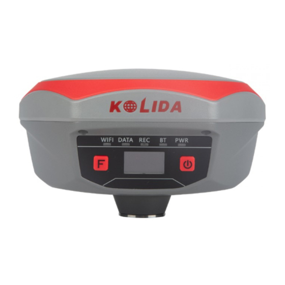
K1Pro ChapterⅡ Hardware Structure In this chapter, we can have knowledge on K1Pro hardware structure and basic function. § 2.1 Components of The Receiver K1Pro size is 163mm in diameter and 96mm in height. The whole shell is made of magnesium alloy material, which makes K1Pro more rugged and durable. - Page 9 K1Pro Indicators The indicators are located at the left side of front panel, for details meaning please check the table below. Component Description WIFI Flashes in red to indicate that WIFI hotspot is broadcasting normally as AP mode. DATA UHF mode: Flashes in red to indicate that the signal is receiving/transmitting with the interval Network mode: 1) Fast flashes in red to indicate that the receiver is dialing;...
- Page 10 K1Pro ⑤ ⑥ ④ ① ⑦ ② ③ Coordinates page ⑧ ⑨ ⑩ Skyplot page Component Description ① Display the remaining power in real-time Battery symbol ② Display the coordinates Coordinates ③ Solution/Message type In base mode, it will display the base's transmitted correction message type;...
-
Page 11: Side View
K1Pro symbol will change to be ; when it shows that means the receiver is broadcasting its WIFI hotspot (We recommend to turn it off while unused.) ⑦ Data link symbol K1Pro will indicate the current used datalink at this location. -
Page 12: Lower Housing
K1Pro § 2.1.3 Lower Housing ④ ⑤ ⑥ ③ ① ② Component Description ① SIM card Slot Where we can insert a SIM card when the receiver is set in GPRS mode ② Serial number of the Apply for a registration code, Bluetooth ID receiver ③... -
Page 13: Mode Select
K1Pro Press F key to move the config option from one to another, and press Power key to confirm. § 2.2.2 Mode Select In the configuration interface, press F key to access Mode Select option and press Power key to confirm. - Page 14 K1Pro antenna height, sampling interval, record mode and data type. Site: this is point ID for static, and it is the last 4 digits from serial number, but you can edit it if you choose this item, there are 0-9 and A-Z for each digit. Ant.Hgt: This is the antenna height measure from ground point to measurement tape Interval: This is the sampling rate for raw data storage Rec.Mode: Auto indicates to collect static data automatically when the environment is OK;...
- Page 15 K1Pro Base Mode Setting Press F key to select Base mode in Mode Select Interface and press Power key to confirm. Start Base Option This option is to set up base transmission parameters. Base Mode: Manual, Repeat and AutoBase for optional to start the base station. Diff Type: This is the correction format which base support to transmit, there are RTD, RTCM23, RTCM30, RTCM32,CMR, SCMRX for optional.
- Page 16 K1Pro Record Option This is used to set raw data collection parameters for base station. Rover Mode Setting Press F key to select Rover mode in Mode Select Interface and press Power key to confirm. Rover Setting This is used to configure the mask angle and SBAS satellite view for rover receiver Mask Angle: The minimum GPS satellite elevation angle permitted by a particular receiver design.
-
Page 17: Datalink Setting
This is used to set raw data collection parameters for rover station. § 2.2.3 Datalink Setting KOLIDA K1Pro is integrated with built-in UHF radio module, cellular module, bluetooth and WIFI, etc. K1Pro also can connect to external radio. When datalink is not used, we can close datalink to save power. - Page 18 K1Pro UHF Setting After selecting UHF option and in the configuration interface, we can set the channel, air baud rate, communication protocol and power for internal UHF. Channel: This is the communication channels for internal UHF, the value of the channel must be the same in both Base and Rover.
- Page 19 K1Pro Cellular Net Setting This mode is to use the internal cellular module that connects to internet and access to reference station for the corrections. Dual Transmitting Mode This mode enables Base station to transmit corrections by internal UHF and cellular net at the same time.
- Page 20 K1Pro WIFI Datalink Setting This is to use WIFI as the datalink that connect to the internet and access to reference station for corrections. External Device This mode enables receiver to connect external radio. Close Datalink This option is used to turn off all of the transmission method for development and customization, usually we keep all the datalink activated.
-
Page 21: System Setting
K1Pro § 2.2.4 System Setting In the configuration interface, press F key to access System Option and press Power key to confirm. And then we can do configurations including Language setting, Voice option, self-check, online service, Online Option, Other Option and Copy Static File items. Language In language interface, we can set the receiver language into Chinese, English, Russian, Korean, Spanish, and Portuguese, Etc. - Page 22 UHF, cellular module and Bluetooth module. Online Option This online service option is used for registration and upgrade firmware online for KOLIDA K1Pro, it is very convenient that you don‟t need any more PC software to do this.
- Page 23 K1Pro USB Mode: When we connect K1Pro to PC by 7-pin USB cable, there are two kinds of USB mode for selection: USB Disk and Ethernet (USB Network). If USB Disk is selected, then K1Pro' internal memory will display in PC, and we can access to the memory to copy static data.
- Page 24 K1Pro DisplaySV: DisplaySV enables us to decide which satellite constellation displayed in skyplot page on screen. The default setting is to display GPS. Power: If we select Saving, when there's no operations in a long time, the screen of K1Pro will turn off to save power automatically.
-
Page 25: Wifi Config
K1Pro § 2.2.5 WIFI Config In the configuration interface, press F key to access WIFI Config and press Power key to confirm. WIFI Info If the WIFI working mode is selected to be “Client”, the connected WIFI information will be displayed at WIFI Info page. - Page 26 WIFI working mode setting For the WIFI working mode, it is not only to be the hotspot, but also to be a datalink that help KOLIDA K1Pro to connect to internet and obtain corrections from reference station. - 26 -...
-
Page 27: Datalink Info (Only For Base/Rover)
K1Pro AP: This item means the WIFI hotspot broadcasted by K1Pro for mobile terminals such as smartphone or tablet to connect and access the Web UI. Client: If this item is selected, K1Pro will connect to the internet via WIFI connection and then download the corrections from reference station. -
Page 28: Config Mode
K1Pro WIFI Status If the WIFI is selected to be current datalink for Base or Rover, the WIFI Status item will be displayed at the main configuration page, press F key to move the select box to this item and then press Power key to enter its page to view more information. -
Page 29: Power Off
K1Pro § 2.2.8 Power Off There are two ways to power off receiver. One is to hold power button for 3 seconds directly; the other is to Press F key in configuration interface to access Power Off interface. In Power Off interface, we can select OFF to power off receiver or select RESET to restart receiver. -
Page 30: Chapterⅲ Web Ui Configuration
ChapterⅢ Web UI Configuration § 3.1 Overview With the help of smart embedded Linux operating system and KOLIDA intelligent cloud technology, we can configure and monitor the status of K1Pro on WEB UI. There are two ways to access K1Pro' WEB UI, by WIFI hotspot and by USB Ethernet mode. -
Page 31: Web Ui Main Interface
K1Pro § 3.2 Web UI main interface After connecting to K1Pro' WIFI hotspot, we can input 10.1.1.1 in browser and the login page will appear. IP Address Username/password - 31 -... -
Page 32: Status
K1Pro In the Web UI home page, Status, Configuration, Satellite Information, Data Record, Data Transfer, Network Config, Radio Config, Firmware Update, User Management and Help are listed at left side. And the positioning informaiton including positioning information and satellites are diplayed at right side. Component Description Positioning information, satellite tracking and the others will... - Page 33 K1Pro Help Offers solutions § 3.2.1 Status System Information, Work Status and Position Information are listed under Status menu. System Information In this page, information such as serial number, hardware ID, MAC address, firmware version and so on are displayed. Work Status K1Pro' status such as working mode, datalink, receiver temperature, remaining power and the free memory is displayed on this page...
-
Page 34: Configuration
K1Pro Position Information In this page, we can have a clear glance at current K1Pro position and detected satellites information. § 3.2.2 Configuration General Config, Base Setup, Antenna Setup, Satellite Tracking, Receiver Operate and Default Language are contained under Configuration menu. Users are able to configure all kinds of - 34 -... - Page 35 K1Pro to your local dealer to apply for another available code, then input the code into the blank or register the receiver online. KOLIDA K1Pro is allowed to setup the working mode and datalink from this Web UI that only need the mobile phone or tablet PC is able to connect the wifi hotspot of K1Pro.
- Page 36 K1Pro Work Mode: There are Rover, Base and Static contained in this dropdown list Datalink: In the list, we have multible datalink options such as Radio, Network, External, Bluetooth and WIFI. Radio Route: This function enables K1Pro to connect to reference station by network and transfer reference station's differential corrections to other receivers by radio.
- Page 37 K1Pro what kind of correction format is transmitted. CMR ID/RTCM2.X ID/RTCM3.X ID: Users can specify the ID for transmitting correction. Position: Click this button to capture the coordinates for current position Spare: This is used to the repeat station Base Start Mode: Here contains 3 methods to start the Base, manually start base, automatically start base by fixed point, automatically start base by current point.
- Page 38 K1Pro Antenna Height: This is the value for height of antenna while surveying. Measuring Method: Here provides several methods for measuring the antenna height such as carrier phase center, slant height, antenna edge, height plate and to the bottom. Satellite Tracking In this page, users can define the mask angle for satellite tracking, and check on the box of corresponding band from the constellation that to use this band or not - 38 -...
- Page 39 K1Pro Receiver Operate The page provides all kinds of operations to control the receiver such as self-check operation, clean epochs, factory reset, reboot and power off. Self-check: Users can also do the self-check from this configuration page, click on the Check all button to check all the modems or click on the check button corresponding to the modem to check one by one.
-
Page 40: Satellite Information
USB: This is used to configure K1Pro what kind of mode output from 7-pin port when connect the receiver with computer via USB cable. USB and network port for optional. Default Language: Configure the default language for KOLIDA K1Pro. Authority Zone: C means this receiver works in China only/ W means it works worldwide §... - Page 41 K1Pro Tracking Chart Tracking Chart is to show the used satellites' SNR (signal noise ratio). Skyplot Skyplot is to show the used satellites sky position. - 41 -...
- Page 42 K1Pro GPS on/off For all the running GNSS constellations or the augmentation system, K1Pro allows to configure to use which satellite or not. In gnss on/off page, all the running satellites are listed, and unselect the box corresponding to the satellite to not use it.
-
Page 43: Data Record
§ 3.2.4 Data Record The “Data Record” is mainly used to configure all the parameters for receiver in static mode. Much more operations can be done on KOLIDA K1Pro such as storage path, interval, data format and data files download. -
Page 44: Data Transfer
K1Pro Data Download This interface is to download collected raw data. § 3.2.5 Data Transfer This function contains General, Serial Port Config, TCP/IP Config, NTRIP Config and Data Flow Config. The “Data Transfer” allows to configure the output mode for raw observation data and differential data, as well as to the NTRIP performance configuration. - Page 45 Navigation Data: This is the navigation data output from receiver such as NMEA-0183, GSV, AVR, RMC and so on. It is configured in Data Flow Config page. SIC Observation Data: This is the user-defined format observation data from KOLIDA. OpenSIC Observation Data: This is the open version of KOLIDA user-defined format...
- Page 46 IP and port for server, and the data format what is uploaded. Then users are able to see the uploaded data on server. Server: KOLIDA K1Pro will upload the data onto internet by the static WIFI if server is selected, then users are able to obtain its dynamic data by accessing to K1Pro through the IP from receiver.
- Page 47 Active: Check on this circle to activate this function. Authentication Mode: These two modes use different protocol standard for the connection, Eagle Mode is KOLIDA standard mode, and TCP/IP Mode is for private network use, usually, choose the Eagle mode for the default setting.
- Page 48 HHHH_RTCM30 NtripCaster This feature is finally realized on KOLIDA K1Pro, the receiver is equivalent to a CORS system that it generates and broadcasts the user-defined correction for rover if K1Pro connects a static IP address.
-
Page 49: Network Config
K1Pro output or not to output what kind of data format. Click on the dropdown list for each data format to define the update rate § 3.2.6 Network Config The “Network Config” is able to configure the ways and the contents for internet access of K1Pro. - Page 50 K1Pro WIFI Config This is mainly used on the WIFI configuration for KOLIDA K1Pro, there are AP mode and Client mode for optional. This is used to enable the WIFI hotspot for K1Pro to broadcast for mobile terminals such as smartphone or tablet to connect and access the Web UI.
- Page 51 K1Pro Client: This option enables K1Pro to search and connect the other WIFI hotspot which connects to the internet, the receiver is able to download and use the mountpoint from reference station. Client_SSID: This is the WIFI hotspot which sis going to connect Scan: Click this button to search the surrounding available WIFI hotspot.
- Page 52 K1Pro Bluetooth Config In this page, users can view the information and connection status of Bluetooth, such the MAC of Bluetooth, discoverable or not, the PIN code, and the connection devices in following table. Port Forwarding This page is mainly used to view and configure the internet transmission port for K1Pro, customize and debug receiver.
- Page 53 NOTE: Usually we will keep the default setting in this page, if you would like to modify it, please contact with KOLIDA technician for more supports. Network Testing This function is mainly used to test network status for K1Pro after logging on the internet.
-
Page 54: Radio Config
Data Baud Rate: This represents the rate of data transmission port of internal radio, this rate should be the same in both Base and Rover. In general, the data baud rate of KOLIDA radio module has been unified to be 19200, keep it as default. -
Page 55: Firmware Update
Update the latest firmware for receiver or for corresponding modems can be done in “Firmware Update”. Firmware Update We can update the firmware of receivers and modules in this interface. Online Update: KOLIDA K1Pro supports to update the firmware online anytime if there is - 55 -... - Page 56 K1Pro something update or optimized. Local Update: Update the latest firmware by using a firmware file. How to upgrade the firmware with Local Update Click on “Browse” button to load firmware file (Please take in mind that the firmware is ended with .img as the extension name).
- Page 57 K1Pro SPECIAL REMIND: KOLIDA K1Pro doesn’t support to update the firmware with the help of INstar program any more, in the future, update the firmware for KOLIDA K1Pro shall be done through the Web UI. Module Update This page is used to update the firmware for corresponding module parts such as GNSS board, radio module, network module and other sensors.
-
Page 58: User Management
K1Pro § 3.2.9 User Management This page is used to manage the authority of login Web UI for users, including the username, password and add users. § 3.2.10 Help In this page, users can get help and check the log book of receiver (the log book can help to backtrack the working status of receiver). -
Page 59: Chapterⅳ Data Collector T17N
ChapterⅣ Data Collector T17N § 4.1 Basic introduction to the handheld Here takes T17N for example (If you want to know more about KOLIDA controller, please go to KOLIDA website http://www.kolidainstrument.com/ for for informaiton), appearance of T17N: - 59 -... - Page 60 K1Pro The yellow sections are the system defaults, and the functions of the 4 hotkeys are below: F1: Start menu. F2: Off. F3: Camera. F4: System main interface - 60 -...
- Page 61 K1Pro The other keyboard operation: System defaults to the digital input method System Default Lowercase letters Switch between / and - Press↑(shift) Press↑(shift) again, it will be digital input method Capital letters Switch between / and - Press the Caps button again for lowercase letters Press Caps Charging DC adapter: Open the DC IN cover on the right side, and charge with a specialized DC...
- Page 62 K1Pro Insert the SIM card and TF card according to the instructions in the battery cabin. Insert the battery according the instructions on the battery label. Close the back cover and turn the back cover screw to the lock position. - 62 -...
- Page 63 K1Pro Power on/off Make sure the battery has enough power, or connect the T17 to a DC adaptor. Press power button for 3~5 seconds to turn on (until the boot screen appears). Press the power button for 3~5 seconds, and confirm to power off. NOTE: If there are abnormal situations, such as the T17 cannot operate normally, use the tip of the stylus to press the reset key to restart the T17.
-
Page 64: Software Installation And Connecting
K1Pro How to use GPS Go to \My Device\GNSSViewer and run GNSSViewer.exe T17 supports COM3 and COM5 GNSS ports and its BaudRate is 9600. Choose a GPS Port and BaudRate by clicking Setup->Port Setup as indicated below. Click „OK ‟. If you want to check the working status of GPS via checking or collecting software, please set the COM port to COM6 and the baud rate to 57600. - Page 65 K1Pro computer, connect handheld to computer with a cable, and install EGStar into the handheld, at the same time, keep the mainframe power on, then set as follows: Open EGStar software and enter the main interface. Click “OK” on the "prompt" window. 2.
-
Page 66: Chapterⅴ Accessories
K1Pro ChapterⅤ Accessories § 5.1 Instrument Case and Accessories ① ① ⑦ ⑨ ⑧ ⑤ ② ② ⑥ ④ ③ ③ ⑨ ④ ⑥ Base Receiver and Accessories Rover Receiver and Accessories ① --- Instrument Case ② --- K1Pro Receiver ③... -
Page 67: Portable Battery Case (Power Bank)
⑤—— Power supply cable, this cable is used to connect the power source to receiver. § 5.3 Other Cables and Accessories 7-pin to OTG cable This cable is used to connect an external storage directly to KOLIDA K1Pro for static data storage and copy. - 67 -... - Page 68 K1Pro USB interface Communication cable This cable is used to connect the receiver to computer for receiver debugging, differential data checking and firmware update. Serial port, connect to computer 5-pin port, connect to receiver Other accessories include carbon-fiber pole, handheld controller bracket, tribrach, connectors, height measuring plate and measuring tape.
-
Page 69: Chapterⅵ Measuring Operation
K1Pro ChapterⅥ Measuring Operation Reading this chapter, you can grasp in detail how to use the K1Pro measurement to do system static, RTK operations. GPS measurement operation scheme refers to the operating scheme used to determine the relative position between the stations with the help of GPS technology. Point coordinate precision obtained is not the same;... -
Page 70: Operating Procedures
Project acceptance § 6.1.3 Field Operation Notes 1)Static mode of KOLIDA K1Pro receiver can be set in EGStar software or other software (Such as SurvX, Field Genius or SurvCE), also can be performed by receiver keypad. 2)Set up a tripod on the control point, leveling and centering strictly on the measuring point. -
Page 71: Gps Net Design
K1Pro 5)Power on, confirm the static mode, the mainframe begins to search satellites and satellite lights begin to flash. Recording condition reached, the status light flashes in accordance with the set sampling interval, flashing once indicates the acquisition of an epoch. 6)After the test, the mainframe shut down, and then begins data transmission and data processing (data transmission sees Chapter IV, data processing, please read another manual GPS data processing software operation manual). -
Page 72: Antenna Height Measurement
K1Pro and consistency. General speaking, the amount of baselines has such limit as follows: The advantage of circle net is the small workload, good self-checking and consistency. But the main disadvantage is that the accuracy of indirect-observed border is lower than that of direct-observed border, and the baseline accuracy of neighbor points distributes unevenly. - Page 73 K1Pro Measuring plate We use a formula to calculate antenna height. “h” is the inclined height that measure from point on the ground to the measuring plate edge. is the distance from middle of antenna to the edge of measuring plate. is the distance from antenna phase center to the bottom of receiver (measuring plate).
-
Page 74: Rtk Measurement
K1Pro § 6.2 RTK measurement RTK is the abbreviation of Real-Time Kinematic measurements. RTK technology is the real-time dynamic differential carrier phase positioning technology, combining global satellite navigation and positioning technology with data communication technology which includes base station and rover station. Base station transmits the data by radio or network to the rover station, which will perform differential analysis, thus providing real-time coordinates of the measurement point in the specified coordinate system. - Page 75 K1Pro § 6.2.1.1 Base Station Set up Base station shall be set up in the broad view, unobscured and higher places; avoid the vicinity of the high-voltage power transmission equipment and the transmitting and receiving antennas of radio communication equipment, the shade of trees, and the sides of waters, all of which will produce different degrees of impact on the GPS signal reception and emission of radio signals Set a tripod to the location with known coordinates (or unknown), attach base receiver to the tribrach adapter set (the measuring plate is recommended to install under base receiver).
- Page 76 Check the box of “Base” option and click “OK” and return to Instrument setting page. At this moment, KOLIDA K1Pro prompts the correct working mode with voice guide. Then tap on “Work mode setting” and then check the box of “Set data link”, then click on “Next”...
- Page 77 K1Pro Then tap on the symbol to save and complete the parameters. 10) Input the coordinates for base location or tap on the symbol to obtain a single position for base. 11) After all the parameters are completely set, click on “Start” button to start the base station. REMIND: If the base station is still set up on the same position next time, check the box of “repeated station”...
- Page 78 K1Pro Using internal Web UI Connect KOLIDA K1Pro with computer via 7-pin to USB cable and set the USB port to output as Ethernet on K1Pro. (a driver is required to installed on computer to enable this function). Login the internal Web UI of K1Pro with the default username and password (admin/admin).
- Page 79 K1Pro Get into “Radio Parameters” interface under “Radio Config”, configure the radio parameters for base station such air baud rate, channel value, power and protocol. - 79 -...
- Page 80 K1Pro § 6.2.1.3 Rover station set up After verifying the successful transmitting of the Base station, the rover station shall be set up at this moment. Install the bracket holder onto the carbon fiber pole, and fix the controller into the bracket, then power on the controller.
- Page 81 Tap on “Work mode setting” and then check the box of “Set work mode”, then click on “Next” to continue; Check the box of “Rover” option and click “OK” and return to Instrument setting page. At this moment, KOLIDA K1Pro prompts the correct working mode with voice guide. - 81 -...
- Page 82 K1Pro Then tap on “Work mode setting” and then check the box of “Set data link”, then click on “Next” to continue; Check the box of “Internal radio” option and click “OK” to complete the settings. - 82 -...
- Page 83 “Switch” button to apply this channel value. Using Web UI Connect KOLIDA K1Pro with computer via 7-pin to USB cable and set the USB port to output as Ethernet on K1Pro. (a driver is required to installed on computer to enable this...
- Page 84 K1Pro function). Login the internal Web UI of K1Pro with the default username and password (admin/admin). Get into “General Config” interface under “Configuration”; Choose “Rover” in “Work Mode” and “Radio” for “Datalink”, then click “Enter” button to save configurations; Get into “Radio Parameters” interface under “Radio Config”, configure the same radio parameters as set on base station for rover station such air baud rate, channel value, power and protocol - 84 -...
-
Page 85: By Using Radio (External Radio)
K1Pro § 6.2.2 By using radio (external radio) § 6.2.2.1 Base station setup Set a tripod to the location with known coordinates (or unknown), attach base receiver to the tribrach adapter set (the measuring plate is recommended to install under base receiver). Mount the UHF antenna set onto a tripod, and connect it to the external radio which is linked with the external power supply via the multi-function cable. - Page 86 K1Pro At least 2m away NOTE: place the 2 tripods at least 2m away from each other against signal interference. Using EGStar3.0 Set the base receiver as base working mode from “Config—Device Config—Instrument Config—Work mode setting—Set work mode--Base”, choose the External option in “Set data link”.
-
Page 87: By Using Internet (Gprs)
K1Pro § 6.2.2.2 Radio settings Make sure all connections are alright, then power on the radio by pressing power button, and then press “C” button to define the channel for data transmission. Please keep in mind the channel is selected to match the settings in controller later on. Radio starts to transmit when TX LED is flashing. - Page 88 K1Pro Input a name for NTRIP connection and choose “NTRIP-VRS” for “Mode” and choose “GPRS/CDMA” for Connect. Then click on “Change” button to define the ANP for your local SIM card. - 88 -...
- Page 89 K1Pro Input the IP address and port, then input the assigned username and password for your NTRIP connection. Press “Get Sourcetable” button to obtain mountpoint list, then select the appropriate one from the list in Access option, press “OK” button to confirm and return to Network Setting interface.
- Page 90 K1Pro NOTE; the parameters would be automatically saved up once input, the receiver would track the CORS info most recently input and connect when it gets started next time. Web UI settings Login the web UI of K1Pro and go to “General Config” interface, then choose “Network” in “Datalink”...
-
Page 91: By Using Internet (Wifi)
“Enter” button at the bottom to access. § 6.2.4 By using internet (WIFI) WiFi datalink is a new feature and new technology adopted on KOLIDA K1Pro, it is more faster and stable in network RTK job. Set the receiver as rover with WIFI mode on the control panel or on Web UI. - Page 92 K1Pro Instrument settings After choosing the rover mode for receiver, then press F button and get into the “Set Data Link” configure page, then move the select box to “WIFI Datalink” option and press power button to confirm. Then get into the “WIFI Config” configure page to check if the WIFI connection is already established.
-
Page 93: Inertial Measurement (Imu)
K1Pro Click on the “Scan” button to search the surrounding available WIFI hotspot, then select a proper one and input the password, click the “Enter” button at the bottom to confirm and access If the WIFI connection is successfully connected, go to “NTRIP Config” interface under “Data Transfer”, and input the CORS server information including IP, Port, User and password, then click “Get Point”... - Page 94 K1Pro activated in a few seconds. K1Pro IMU supports tilt survey in as much as 60 degrees angle. Without leveling, K1Pro IMU' positioning efficiency has been increased by over 30%. And at the same time, the algorithm of IMU+GNSS will guarantee a stable and accurate positioning result.
- Page 95 K1Pro 2. Work at Non-signaled Point 3. Conveniently Measure Inaccessible Points SPECIAL REMIND: Please run this Website for more IMU info: https://www.linkedin.com/pulse/inertial-measurement-rtk-k5-imu-bring-your-producti vity-andy-lau/?published=t - 95 -...
-
Page 96: Star-Link & Star-Fill
Star -Link KOLIDA Star-Fill is a new service that extends RTK positioning for several minutes when the RTK correction stream is not available. KOLIDA Star Fill corrections are broadcast by satellite, so they are generally available within covered areas wherever the GNSS constellations are visible. - Page 97 K1Pro value and protocol that are selected to match on rovers later on. Then choose “Network” for Datalink option and choose “internal radio” for Router option in “General Config” page, click on “Enter” button to confirm the settings. At this moment, configure the parameters for rover to access to the CORS server for corrections. Then the other rovers are able to connect the rover router via internal radio with the same channel value, after rovers have fixed solution, the base coordinates are same as CORS station.
-
Page 98: Appendix A Kolida K1Pro Technical Specifications
K1Pro Appendix A KOLIDA K1Pro technical specifications GNSS characteristics: ■ 336 GNSS channels (672 channels optional) - GPS : L1C/A, L1C, L2C, L2E, L5 - GLONASS : L1C/A, L2C/A, L2P, L3 - BeiDou: B1, B2, B3 - Galileo: E1, E5A, E5B,E5AltBOC,E6 - IRNSS: L5 - SBAS: L1C/A, L5 (QZSS, WASS, MSAS, GAGAN, EGNOS)... - Page 99 K1Pro Real-time kinematic (RTK) ■ Horizontal: ±8mm+1ppm ■ Vertical: ±15mm+1ppm Network RTK ■ Horizontal: ±8mm+0.5ppm ■ Vertical: ±15mm+0.5ppm RTK initialization time ■ 2~8s Physical characteristics Size ■ 16.3 x 16.3 x 9.6 cm Weight ■ 1.33 kg (with built-in battery) User interface ■...
- Page 100 ■ External DC power: 9-28 V UHF Radio characteristics ■ Built-in radio, 120 channels ■ Frequency Range 410-470MHz ■ Protocol: TrimTalk450s, TrimMark3, SOUTH (KOLIDA), Hi-target, CHC, Satel ■ 1W/2W/3W switchable ■ typically working range 7-8km ■“Barrier-Free” Measurement Technology: Repeater/ Router Cellular module characteristics ■...
-
Page 101: Appendix C Technical Terms
K1Pro Standard system components ■ K1Pro GNSS Receiver & built-in battery ■ Charger and adapter ■ All-direction antenna ■ 30 cm pole extension (with base only) ■ 7-pin to OTG cable ■ Field software: Engineering Star (Windows Mobile) ■ Post-processing software: KGO (Windows PC) ■... - Page 102 K1Pro for the 1023 bit duplex, the bit rate of which is 023MHz, and code repetition period of 1ms. Difference measurement: GPS measurements employ cross-satellite cross-receiver and cross-epoch. Difference Positioning: the method of determining the relative coordinates between two or more receiver by tracking the same GPS signal. Geometric dilution of precision: Describe the contribution of satellite geometry errors factor in dynamic positioning ...
-
Page 103: Fcc Statement
K1Pro FCC Statement This equipment has been tested and found to comply with the limits for a Class B digital device, pursuant to part 15 of the FCC Rules. These limits are designed to provide reasonable protection against harmful interference in a residential installation. This equipment generates, uses and can radiate radio frequency energy and, if not installed and used in accordance with the instructions, may cause harmful interference to radio communications.
Need help?
Do you have a question about the K1 Pro and is the answer not in the manual?
Questions and answers
Offset distance settings steps on kolida GPS controller