Table of Contents
Advertisement
Quick Links
1.FEATURES.......................................................................1
2. PREPARATION................................................................2
2.1 Precautions.................................................................................2
2.2 Appearance................................................................................3
2.3 Unpacking and Storage of the Instrument.................................5
2.4 Instrument Set Up......................................................................5
2.6 Assemble and Disassemble the Tribrach....................................8
2.7 Eyepiece Adjustment and Object Sighting..................................9
2.8 Power On & Off...........................................................................9
2.9 How to Enter Alphanumeric Characters...................................10
3. FUNCTION KEY AND DISPLAY.......................................12
3.1 Operating Key...........................................................................12
3.2 Function Key.............................................................................13
3.3 Star-key.....................................................................................16
4.1 Setting the Temperature and Atmospheric Pressure................18
4.2 Setting of the Atmospheric Correction.....................................19
4.3 Setting of the Prism Constant...................................................21
5. ANGLE MEASUREMENT................................................22
5.1 Measuring Horizontal Angle Right and Vertical Angles............22
5.2 Switching Horizontal Angle (Right/Left)...................................23
5.3 Setting of the Horizontal Angle................................................24
5.3.1 Setting by Holding the Angle..................................................................24
5.3.2 Setting the Horizontal Angle from the Keypad.......................................25
CONTENTS
....................................................................
18
Advertisement
Table of Contents

Related Manuals for Kolida CTS-632R10M


Summary of Contents for Kolida CTS-632R10M
-
Page 1: Table Of Contents
CONTENTS 1.FEATURES...............1 2. PREPARATION..............2 2.1 Precautions.................2 2.2 Appearance................3 2.3 Unpacking and Storage of the Instrument.........5 2.4 Instrument Set Up..............5 2.5 Battery Removal & Insertion – Information and Recharging..7 2.6 Assemble and Disassemble the Tribrach........8 2.7 Eyepiece Adjustment and Object Sighting........9 2.8 Power On &... - Page 2 5.4 Vertical Angle Percent Grade (%) Mode........26 5.5 Setting the Initial Zenith Angle..........27 6.DISTANCE MEASUREMENT..........28 6.1 Setting of the Atmospheric Correction........28 6.2 Setting of the Correction for Prism Constant......28 6.3 Distance Measurement (Continuous Measurement)....28 6.4 Changing the Distance Measurement Mode......29 6.5 Stake Out(S.O.).................31 7.COORDINATE MEASUREMENT........33 7.1 Procedures of Coordinate Measurement.........33...
- Page 3 10.2 Coordinate inverse calculation..........68 10.3 Area/ Perimeter..............69 10.4 Point to Line Inverse...............71 11. PROGRAM..............73 11.1 Road..................74 11.1.1 Horizontal Alignment Data..............75 11.1.2 Vertical Alignment Data...............79 11.1.3 Road Stake Out..................81 11.1.4 Calculation...................83 11.1.5 Road select...................83 12. Station…..............84 12.1 Known Point................84 12.2Resection.................89 12.3 Point to Line Measurement............90 12.4 Height Transfer……..............92 12.5 Backsight Check..............94 13.DATA................95...
- Page 4 13.7 Memory................103 13.8 Format..................104 14.SETTING..............105 14.1Measure Parameter...............106 14.1.1Angle Parameter..................106 14.1.2 Distance Setting.................106 14.1.3 Coordinate Settings................107 14.2 Unit Setting................108 14.3 Serial Comm Setting.............108 14.4 Backlight Setting..............109 14.5 Time/date Setting..............110 14.6 Other Setting................110 15.CHECK AND ADJUSTMENT.........111 15.1 Plate Vial................111 15.2 Circular Vial................112 15.3 Compensator................112 15.4 Inclination of Reticle.............114 15.5 Perpendicularity of Line of Sight to Horizontal Axis (2c)..115...
- Page 5 15.12 Related Parts for Reflector..........122 16.SPECIFICATION ............113 17. ERROR DISPLAYS............126 18. SAFETY INSTRUCTIONS..........126 18.1 Integrated EDM (Visible Laser)..........125 18.2 Laser Plummet..............128...
-
Page 6: Features
Automatic Data Collection Automated field data collecting program, can record measurement data and coordinate data automatically, CTS-632R10M can also transfer data to PC directly, realize the real digital survey. Lighter Telescope Lens This new generation total station has more scientific and reasonable design in appearance and internal structure, the smaller telescope makes the measurement more convenient. -
Page 7: Preparation
2. PREPARATION 2.1 Precautions 1). Please do not aim at the sun. If you need to do the outside working under sunshine, please use a filter. 2). Please do not store the instrument in extreme temperatures and also avoid sudden change. 3). -
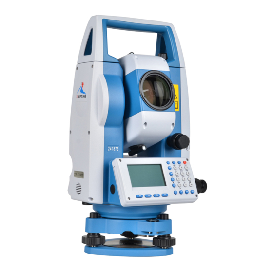
Page 8: Appearance
2.2 Appearance Collimator Instrument Center Mark Vertical Tangent unit Laser Plummet RS232/ SD Card/ USB Display Unit Leveling Screw Tribrach Clamp... - Page 9 Object Lens Battery Horizontal Tangent Unit EDM Trigger Key Circular Vial...
-
Page 10: Unpacking And Storage Of The Instrument
2.3 Unpacking and Storage of the Instrument Unpacking of the Instrument Place the case lightly with the cover upward, unlock the case and take out the instrument. Storage of the Instrument Replace the cover on the telescope lens, place the instrument into the case with the vertical clamp screw and circular vial upward (objective lens toward the tribrach), tighten the vertical clamp screw, close and lock the case. - Page 11 plate vial parallel with the line connecting leveling screw A and B, then bring the bubble to the center of the plate vial by turning the leveling screws A and B. Rotate the instrument 90° (100gon) around its vertical axis and turn the remaining leveling screw or leveling C to center the bubble once more.
-
Page 12: Battery Removal & Insertion - Information And Recharging
2.5 Battery Removal & Insertion – Information and Recharging Insert the battery into the battery slot and push the battery until it clicks. Press the right and left buttons of the battery compartment to remove the battery. Battery information Please stop the operation when battery is in low voltage, and change a recharged battery for operation. -
Page 13: Assemble And Disassemble The Tribrach
2.6 Assemble and Disassemble the Tribrach Disassemble If necessary, you can disassemble the tribrach from CTS-632R10M. Loosen the tribrach locking screw in the locking knob by a screwdriver. Turn the locking knob 180 degrees counter-clockwise to disengage anchor jaws and remove the instrument from the tribrach. -
Page 14: Eyepiece Adjustment And Object Sighting
Assemble Insert three anchor jaws into holes and line up the directing stub on the instrument with the directing slot of the tribrach. Turn the locking knob 180 degrees clockwise and tighten the locking screw by a screwdriver 2.7 Eyepiece Adjustment and Object Sighting Method of Object Sighting (for reference) Sight the telescope to the sky and rotate the eyepiece tube to make the reticle clear. -
Page 15: How To Enter Alphanumeric Characters
2.9How to Enter Alphanumeric Characters This Chapter is introducing how to input the alphanumeric characters, such as Instrument height, Prism height, station points and BS point etc, selecting * item and input of numbers. [Example 1] Select I.HT (instrument height) in the data Set Stn (first press the MENU button then 5: Set Stn and then press F4,. - Page 16 *How to enter characters *Example 2+ Input the code “ABCDE” for measuring point in Set Stn Mode Known Pt. 1.Press [▼] or [▲] key to move the arrow,when move to the inputting item,press the switch key α Press [7] key once for “A” Press*7+ key twice for “B”...
-
Page 17: Function Key And Display
3. FUNCTION KEY AND DISPLAY 3.1 Operating Key Keys Names Function Angle meas. Angle measurement mode Distance meas. Distance measurement mode Coordinate meas. Coordinate measurement mode Backspace Delete characters before cursor Direction key [▲] Up [▼] Down Direction key ]Left [ ]Right Escape Return to the measurement mode or previous page... -
Page 18: Function Key
Display marks: Display Content Vertical angle as a percentage (Gradient display) Horizontal angle (right/left) Atmospheric correction 3.2 Function Key Angle measurement mode ↓ ↓ ↓ ↓ Page Soft keys Display marks Function 0SET Horizontal angle is set to 0°0’0” HOLD Hold the horizontal angle HSET Set a required horizontal by entering numbers... - Page 19 Distance measurement mode ↓ ↓ ↓ ↓ Page Keys Display Function MEAS Begin measuring MODE Sets measuring mode, Fine/--/Tracking Select Stake Out measurement mode Coordinate measurement mode ↓ ↓ ↓ ↓...
- Page 20 Page Keys Display marks Function MEAS Start measuring MODE Sets a measuring mode, Fine/Tracking Sets instrument coordinate Shows the function of soft keys on page 2 R.HT Sets prism height I.HT Sets instrument height Setting coordinate for back sight orientation Shows the function of soft keys on page 1...
-
Page 21: Star-Key
3.3 Star-key Press the star key, following is displayed: 6. Settings Press 1. Target , shown as below: Three cooperation target could choose: Non-prism, Prism and Sheet, choose one mode then press [OK] return the last page. Note: In the prism mode, you can change the prism constant, as the default setting is “-30”. E bubble: electronic bubble can be adjust in this page.. - Page 22 Meas mode: Press [ ] or [ ] to switch Fine, Repeat and tracking measurement, press “OK” to confirm. Note: You can choose the measurement times in Fine measurement mode, as following image: Laser Pointer: On or off the EDM laser pointer Settings : Setting for Battery management, Back-light setting, Cross-hair back-light Laser plummet(Only for TS with Laser plummet): Control the on/off and luminescent of Laser plummet, choose [OK] to finish, as following image:...
-
Page 23: Initial Settings
4. INITIAL SETTINGS 4.1 Setting the Temperature and Atmospheric Pressure If the T&P correction of the Total Station is off, you should follow the steps below; If it is on, there is no need to set the Temperature and Atmospheric Pressure, the instrument will detect the Temperature and Atmospheric Pressure automatically, and make the correction with PPM. -
Page 24: Setting Of The Atmospheric Correction
④Input temperature, press OK to confirm. The same setting for Air Input pressure. The instrument will calculate temperature atmospheric correction value *1) automatically Remarks: *1) Please refer to 2.10 “How to Enter Alphanumeric Characters” Temperature operating range: -30°~+60‵(interval 0.1‵) or -22~+140℉(interval 0.1℉) Air pressure range: 560~1066hPa (interval 0.1hPa) or 420~800mmHg (interval 0.1mmHg) or 16.5~31.5inHg (interval 0.1inHg) The setting of Air pressure is same as temperature setting... - Page 25 P: Air Pressure (Unit : hPa If the unit is mmHg , please convert using 1hPa = 0.75mmHg 1mmHg = 1.333hPa T: temperature ( unit‵) Direct Setting Method of Atmosphere Correction Value Operation Procedure Operation Display ①Press star key into quick setting, then press 3 ②Press [▲] or [▼] to PPM ]or[...
-
Page 26: Setting Of The Prism Constant
4.3 Setting of the Prism Constant The default setting of prism constant for the total station is -30mm. If the constant of the prism is not -30mm, you must change this setting. Once the prism constant is set ,it will become the new default value until changed. -
Page 27: Angle Measurement
5. ANGLE MEASUREMENT 5.1 Measuring Horizontal Angle and Vertical Angle Make sure the angle measurement mode is selected Operation Procedure Operation Display ①Aim at the first target (A) Aim Target A ②To set horizontal angle of target A at 0°0’0”. Then press theF1 (0SET) key and then press theF4 (OK) key ③Aim at the second target (B). -
Page 28: Switching Horizontal Angle (Right/Left)
Reference: How to Aim at the Target ①Point the telescope toward a light surface or sky. Rotate the eyepiece ring and adjust the focus so that the cross hairs are clear in your view. ②Aim the target by the peak of triangle mark on the EDM. Allow a certain space between the sighting collimator and yourself. -
Page 29: Setting Of The Horizontal Angle
③Measurement same as HL mode *Each time the F2 (R/L) key is pressed the HR/HL mode switches 5.3 Setting of the Horizontal Angle 5.3.1 Setting by Holding the Angle Make sure the angle measurement mode is selected Operation procedure Operation Display ①... - Page 30 5.3.2 Setting the Horizontal Angle by Manual Make sure the angle measurement mode is selected. Operation procedure Operation Display ①Aim the target ②Press the F3 (HSET) key ③Input the required horizontal angle by using the keys*, for Eg. Input example:150.10.20, inputs 150.1020 150º10’20”.
-
Page 31: Vertical Angle Percent Grade (%) Mode
5.4 Vertical Angle Percent Grade (%) Mode Make sure the angle measurement mode is selected. Operation procedure Operation Display ①Press F4 key to get the function on menu page P2 ②Press the F1(V%)key * *Each time the F1(V%)key is pressed the display mode switches. When the angle measured is less than 45°... -
Page 32: Setting The Initial Zenith Angle
5.5 Setting the Initial Zenith Angle Vertical angle is displayed as shown below: vertical zero Make sure the angle measurement mode is selected. Operation procedure Operation Display ①Press F4 key to get the menu on page 2 ③ Press the F3(VA)key * * Each time the F3 key is pressed the display mode switches. -
Page 33: Distance Measurement
It is necessary to check I angle of the instrument at first. Please refer to the setting steps of V0 ADJUSTMENT (i angle) CTS-632R10M series have three kinds of measuring mode in distance measurement: 1)Prism, need to aim at the target prism. 2).Sheet, need to aim at the target sheet. -
Page 34: Changing The Distance Measurement Mode
②Press the key, distance measurement starts *1)-*4) *1) If you want to set automatic distance measurement after power on, please refer to the steps in Chapter 14 “Setting”. *2) The unit of distance is “m” (meter) in default ,the distance data will be updated after each measurement finished along with the beep. - Page 35 ②Press key*1) ③Press F2 to enter, then press F2,then ]or[ ] to switch between press[ fine mode, repeat mode and tracking mode *1)You can set the measuring mode when CTS-632R10M is power on...
-
Page 36: Stake Out(S.o.)
6.5 Stake Out(S.O.) This function can show the difference between measured distance and the input stake out distance; Measured distance - Stake out distance = Displayed value In a stake out operation you can select either horizontal distance (HD), relative elevation (VD), and slope distance (SD.) Operation procedure Operation... - Page 37 Prism measured distance and the stake out distance is displayed. ⑥Move the target until the value becomes 0 If the value come to zero or switch to other measurement mode, CTS-632R10M will back to normal distance measurement surface.
-
Page 38: Coordinate Measurement
7.COORDINATE MEASUREMENT By entering the coordinate of station point, instrument height ,prism height and the azimuth of Back-sight point, 3D coordinate of Measuring Point can be measured automatically. 7.1 Procedures of Coordinate Measurement Measure the coordinates by entering the instrument height and prism height, coordinates of unknown Point will be measured directly. - Page 39 When doing coordinate measurement, you need to set coordinates of occupied point, the instrument height, the prism height and back-sight azimuth at first. Operation procedure Operation Display Set direction ①Set the direction angle of angle known point A *1) ②Aim at target prism B, and Aim at target prism press...
-
Page 40: Setting Coordinate Values Of Station Point
7.2 Setting Coordinate Values of Station Point Set the coordinates of the instrument (Station point) refer to the origin points in coordinates, then CTS-632R10M can automatically converts and displays the unknown point (prism point) coordinates into this exist coordinate system. -
Page 41: Setting Height Of The Instrument
Enter ③Enter N coordinate value*1) coordinates ④Enter E and Z coordinate values in the same way. Then Enter data the display returns to the coordinate measuring display menu. 7.3 Setting Height of the Instrument The instrument height value will be retained after power off. Operation procedure Operation Display... -
Page 42: Setting Height Of Target (Prism Height)
②Press the F2 (I.HT). The value will show the current Inst.Ht. ③Enter the instrument height Enter the and press the ENT key to back I.H. to the coordinate measuring function. 7.4 Setting Height of Target (Prism Height) This mode can be used to calculate z coordinate values. The target height value will be saved after power off. - Page 43 ② Press F1 R.HT to display the current prism height ③ Input the prism height and Enter the press ENT to confirm and back R.HT. coordinate measuring function...
-
Page 44: Data Collection
8.DATA COLLECTION Data collect menu operation Collect COGO Station Point Measurement (refer to 8.1) F4. OK Data collection Distance Offset Measurement (Refer to 8.2) Plane Offset Measurement (Refer to 8.3) Column Offset Measurement (refer to 8.4) Missing Line Measurement (refer to 8.5) Remote Elevation Measurement (refer to 8.6) -
Page 45: Point Collect
8.1 Point Collect Point Collect has two different modes①: Measure first ②Input first. The difference between two modes is input point name and code at first or not. Choose “Auto” when automatic save is needed. Otherwise, choose “Manual”. Coordinate measurement, angle measurement and distance measurement can be switched anytime when measuring. - Page 46 ④ Input Point name and code first, then press[ ]or[ ] to switch Eg: Distance ⑤Aim at target point ⑥ Press F4 to measure and save automatically ⑦Input the next point name and code, aim at the target ⑧Repeat steps from ④to⑥...
-
Page 47: Distance Offset Measurement
8.2 Distance Offset Measurement Operation procedure Operation Display ① Press 2 key from collect mode ②Input L/R, F/B, U/D offset Input data distance ③ Press F4 key (Next) -
Page 48: Plane Offset Measurement
④Press F1key (Measure) ⑤Press F2key (Coordinate) to get the coordinate of offset point , then F1, Back ⑥PressF4 (Next) in step ④, record the measurement data, then measuring the next point 8.3 Plane Offset Measurement This function is used for the point cannot be measured directly, such as the distance or coordinate of the points on border. - Page 49 Operation procedure Operation Display ① Press 3key from collect mode to enter Plane Offset Measurement. Then choose F1/F2/F3 for measurement, or call or input coordinates. Aim point1, ② Aim at prism point 1,input Input R.HT, R.HT, press F1 (Meas.) key ③...
- Page 50 Aim point2 ④ The second and third point should be measured in same Aim point3 ⑤ Press F4 (Next) key ⑥ Aim at the target point on the plane, the display will show horizontal and vertical angle of the point*1) *2) ⑦...
- Page 51 ⑧ PressF3 (Coordinate) key, show the coordinate of the target point ⑨ Press F4 (ok) key to save the measured data ⑩ Input point name and code(Code also can be called by Press F3 from Code database. *1 ) If three measured point cannot define a plane by calculation, the display will show no intersection ,then the measurement should start from the 1 point again.
-
Page 52: Column Offset Measurement
8.4 Column Offset Measurement Measuring circumscription point (P1) on column at first, then the distance to the center of the column (P0) can be calculated by measured direction angle of circumscription points (P2) and (P3). The angle of center point is equals to the average value of direction angle about P2 and P3. Operation procedure Operation Display... - Page 53 Aim at the ③Press F4 (Next) left direction Aim at the ④Press F4(Next) right direction ⑤PressF4 (Cal.) to calculate the coordinate of center point Press F4 (Save) to save data ⑥Input Point name and Code...
-
Page 54: Missing Line Measurement (Mlm)
8.5 Missing Line Measurement (MLM) Measurement for horizontal distance (dHD) , slope distance (dVD),elevation relative(dVR) and horizontal bearing (HR) between two target prisms. It is possible to enter the coordinate value directly or calculate from coordinate data file. MLM Mode has two modes: 1. - Page 55 ③ Press1 as an example ④ Input start point name. Eg: Input character ⑤ Aim prism A, and press the F1 (MEAS) key. (or Call or Input F1 (MEAS) Coordinate) ⑥ PressF4 to return step ⑤, Press then input end point name, then press Eg:B keyboard...
- Page 56 ⑧ Press F4 ⑨ Press F4 (Calculate) key. HD, VD and SD between A and B will shown as picture ⑩ Measure distance between points A and C, press F4 (Next) key*1) ⑪ Input end point name, Eg: C Press F4 ⑫Aim at prism C and press the F1 (MEAS) key...
- Page 57 ⑬ Press F4 ⑭ Press F4 (Calculate) key. HD, VD and SD between A and C will be shown ⑮ Measure distance between points A and D, repeat procedure ⑩ to ⑭ *1) *1) Press the ESC key to return to previous surface HOW TO INPUT OR READ COORDINATE DATA It is possible to input coordinate values directly or read from a coordinate data file.
- Page 58 ② Press F4 (coordinate) key ③ Input point, continue to measure *To return to Menu, press the ESC key.
-
Page 59: Remote Elevation Measurement (Rem)
8.6 Remote Elevation Measurement(REM) To obtain elevation of the point where setting the target prism is not possible, place the prism at any point on the vertical line from the target then carry out REM procedure as follows 1)With prism height (h) input Operation procedure Operation Display... - Page 60 Input prism ③ Enter prism height *1) height ④ Aim at prism Aim P ⑤ Press the F1 (MEAS) key, measurement starts. Index value between instrument and prism will be shown ⑥ Aim target K. the elevation Aim K (Z) will be shown. *2) *1)Refer to 2.10 “How to Enter Alphanumeric Characters”.
- Page 61 2) Without prism height input Operation procedure Operation Display ① Press 1 key, enter the COLLECT menu ② Press 6 key, enter REM ③Aim the prism and press F1 (MEAS) start measurement. Index value target between instrument prism will be shown ④...
-
Page 62: Stake Out
9. Stake Out The Stake Out mode have two functions, measuring the location of the stake out point and stake out by the known coordinate from internal memory. The coordinate data is stored in a COORD. DATA file. About internal memory, please refer to Chapter “DATA”... -
Page 63: Choose Data File
9.1 Choose data file In stakeout mode, you should choose a coordinate data file first, which will be used for station point and data calling. Also the new measured data can be saved in selected coordinate data file. When stake out mode is operating, you can select file in the same way. Operation procedure Operation Display... - Page 64 2. Call from the coordinate data file For example: Call coordinate from the coordinate data file. Operation procedure Operation Display ① Press 1 (coordinate stake out) key . ②Press F3 (call) ③Choose points from coordinate data, press F1 key to check coordinate ④Press F1 (back) and F3 (OK)
- Page 65 ⑤Press (SO) start stake-out ⑥ Adjust horizontal tangent unit to make the Move level HAD(Horizontal angle screw difference) become value 0, then press Press F1 (Meas.) ⑦PressF3 (1/3) to switch page ⑧When all value in Page 1 and...
-
Page 66: Angle/Distance Stakeout
3 become 0, the stake out has completed ⑨Press F4 (Next Pt) key, into next point stake-out 9.3 Angle/distance stakeout Angle/distance stakeout can be carried out by inputting the relative position relation between stakeout point and station point. Operation procedure Operation Display ①... - Page 67 ③Adjust horizontal Move level tangent unit to make the dHA screw (Horizontal angle difference ) becomes value 0, then press F4 PressF1 (Meas.) ④Press F3 (1/3) to switch When all value in page 1 and 3 become 0, the test built of layout point has completed ⑥Press F4 (Next Pt), into next stakeout point...
-
Page 68: Reference Line Stakeout
9.4 Reference Line Stakeout Reference line stakeout is a new developed module of CTS-632R10M series, the target point will be stake out by comparing the distance relation between stakeout point and the line connected by two known points. Operation procedure... - Page 69 ④Press F4 (Next) ⑤Input setting out point, start from P1 to P2 as the baseline L-R: left, right keypad F-B: forward, back U+D: up, down ⑥ PressF4(Next) enter stakeout page...
- Page 70 ⑦ Adjust horizontal tangent Move unit to make the HAD value leveling becomes 0, then press F4 screw Press F1 (Meas.) ⑧Press F3 (1/3) to switch When all value in page 1 and 3 become 0, the setout has completed ⑨Press F4 (Next Pt) key, into next stake-out point...
-
Page 71: Cogo
10.COGO COGO menu operation procedure Normal measurement mode MENU COGO Coordinate Calculation(refer to 10.1) Coordinate inverse calculation (refer to10.2) Setting calculation file Area and Perimeter(refer to 10.3) 5. Point Projection Point and Line Inverse(refer to 10.4)... -
Page 72: Cal.xyz(Coordinate Calculation)
10.1 Cal.XYZ(Coordinate Calculation) Input or measure starting point, then get the coordinate of target point by input the azimuth, horizontal distance and vertical elevation. The coordinate of starting point has two ways to input: 1. Measure new coordinate point or input coordinate point 2. -
Page 73: Coordinate Inverse Calculation
④ PressF4 (Save) to save the data of the point 10.2 Coordinate inverse calculation Input or measure the starting point and end point, then the instrument can calculate the HD(horizontal distance), SD(slope distance), VD(vertical distance) and azimuth for the line connected by the two points. -
Page 74: Area/ Perimeter
③ Repeat step ② to measure end point ④ Press F4 (Cal.) 10.3 Area/ Perimeter The area and perimeter of graph which composed by those measured points can be calculated by measuring 3 or 3 more points. Operation procedure Operation Display ①Press3 (Area and Perimeter.) from calculation... - Page 75 ②Press F1 (Add) ③Press F1 (measure) ④Press F4 (OK) ⑤Press F4 (OK) ⑥Repeat ②and⑤ step measure other new add point...
-
Page 76: Point To Line Inverse
⑦Press F4 (Cal.) 10.4 Point to Line Inverse Measure 2 starting points P1 and P2 to define a straight line at first, then measure a setting point P3, you can get the coordinate of foot point from P3 to the straight line at last. The coordinate of each point has two ways to input: 1. - Page 77 ③Press F4 (OK) ④Repeat ②and③ step measure P2 and P3 ⑤Press F4 Cal. ⑥Press F4 (Save) ⑦Input this point’s name and coordinate, pressF4 (OK)
- Page 78 10.5 Point Projection Measure 2 starting points P1 and P2 to define a straight line at first, then measure a...
-
Page 79: Program
11. PROGRAM Normal measurement mode MENU... -
Page 80: Road
11.1 Road In ROAD program, you can define a curve formed by straight line, circular curve or transition curve as a reference to take measurement and stake out. The program will take coordinate calculation and stake out to designed point according to the confirmed stake number and difference of road design. -
Page 81: Horizontal Alignment Data
11.1.1 Horizontal Alignment Data Horizontal Alignment Menu Horizontal alignment consisted of following elements: starting point, straight line, circular curve , transition curve. Straight line When the starting point or other line type is well defined it allows you to define a straight line. - Page 82 Transition curve Press F4 key in the “HZ AL Screen” and a transition curve can be defined. The inputting of transition curve consists of transition curve parameter “Para”,starting radius , and ending radius . If the input radius is ∞ you can input 0 as its value. When Rs and Re value is positive, transition parameter A is symbolic number.
- Page 83 Operation procedure Operation Display ① Enter define horizontal alignment, if it is not defined, the display will show the start Enter point page ②Enter alignment data input page by press (OK) key Line ③Choose different alignment to input, then finish the Curve horizontal alignment design Trans...
- Page 84 Edit horizontal alignment Operation procedure Operation Display ①Choose 2 in HZ AL surface. Start Enter edit horizontal Line Curve alignment Enter Trans ② Choose the horizontal Choose alignment to check and edit. Import horizontal alignment Operation procedure Operation Display Enter import horizontal Enter...
-
Page 85: Vertical Alignment Data
11.1.2 Vertical Alignment Data Vertical Alignment Menu A vertical curve consists of series of intersection points. The intersection point consists of a stake number, elevation and curve length. The start/end points and end curve length must be a zero. Operation procedure Operation Display ①... - Page 86 Edit Vertical Alignment Operation procedure Operation Display ①Enter edit vertical alignment ② You can find/check the inputted vertical alignment data, also can edit when you enter check detail information Search View Import Vertical Alignment Operation procedure Operation Display ① Enter define vertical alignment...
-
Page 87: Road Stake Out
Clear vertical alignment Click to CLEAR to delete all the saved vertical alignment data. 11.1.3 Road Stake Out For the road stake out, the line type must be defined. Horizontal and vertical alignment can be defined according to the procedures in the previous sections.(If it does not need to fill or cut,user does not need to define the vertical alignment) Offset Left: the HD between left stake and center line Offset Right: the HD between right stake and center line... - Page 88 Operation procedure Operation Display ① Enter Road SO program, Start input start stake-No., interval, Interval difference vertical distance, then enter next step ② Show the stake-No. and difference information stakeout point, press F4(Next) to start ③ Show the information of stakeout point.
-
Page 89: Calculation
11.1.4 Calculation Single-point coordinate calculation Operation procedure Operation Display Enter single-point coordinate calculation, input mileage and point name, instrument will calculate automatically and save it Batch coordinate calculation Operation procedure Operation Display Enter batch coordinate calculation, input mileage and point name, instrument will calculate automatically and save it 11.1.5 Road select... -
Page 90: Station
12. Station Select a coordinate data file before enter setting a station, used for station measurement and data calling. It can also save the data of new point into the selected coordinate data file. Operation procedure Operation Display ① Press 5 (Set Stn) from the Choose a job menu ②Choose the correct file and... - Page 91 Eg: Set station point from the internal coordinate data file. Operation procedure Operation Display ① Press 1 (Known Pt) from the set station menu ② Press F3 (Call) ③ Choose a point and press F3 (OK) ④Press F4 (Next) to forward back-sight select *There are two different choices of back-sight...
- Page 92 1) Coordinate Operation procedure Operation Display ①Press1 to select coordinate ②Press F3 (Call) ③Press F3 (OK) ④Press F4 (Next), aim at target...
- Page 93 ⑤PressF4 (Orient)key ⑥PressF1 (Measure) key if need ⑦Press F1 (Angle), F2 (Dist.), F3 (Coord.) to get the results, then finish the measurement. 2) Angle Operation procedure Operation Display ①Press2 to select angle...
- Page 94 ②Input azimuth keyboard ③Press F4 (Next) ④ Aim at target, Press F4 (Orient) ⑤Press F1 (Meas.) if needed ⑥ Press F1 (Angle), F2 (Dist.), F3 (Coord. ) to get the data, then finish measurement.
-
Page 95: Resection
12.2 Resection The location of a new point can be determined by observing up to a maximum of seven known points. *Resection by distance measurement: 2 or more points must be measured, the angle between two points should not exceed 180°. The station point coordinate value will be calculated using the least squares method. -
Page 96: Point To Line Measurement
②Input Point name and prism height, then press Dist. key to get the result ③Press (OK) complete the measurement of first point ④Repeat ①to③ step measure several points, it can calculate automatically and show the result once meet the calculation condition, also can check and save the result 12.3 Point to Line Measurement This mode is used to obtain the coordinate data of an unknown occupied point from a... - Page 97 Operation procedure Operation Display ①Press3 (Point to line) from set station menu ②PressF1, measure distance from point A to station point ③Press F4 Next...
-
Page 98: Height Transfer
④Press F1 (Meas.) , measure the distance from point B to station point ⑤Press F4 F4 (Next) ⑥Press F2 (Coord.) to check station point coordinate. Input Input, the point name to save the F4 (set) coordinate. 12.4 Height Transfer his mode is used for adjust the elevation of station point, calculate the elevation of station point by measuring a coordinate of known point. - Page 99 Eg: Call the point coordinate from the file Operation procedure Operation Display ① Press 4 (Height Transfer ) from set Station menu ②Press F3 (Call) ③Press F3 (OK) ④Press F4 (Next)
-
Page 100: Backsight Check
⑤Press F1 (Meas.) ⑥Press F4 (OK) to get the elevation of new station point 12.5 Back-sight Check Operation procedure Operation Display ①Press 5 (BS check) from Set Stn menu ②Press F4 (Reset) key to reset the horizontal angle... -
Page 101: Data
13.DATA Data collect menu operation: Normal measurement mode MENU Job(refer to13.1) Measurement Data (refer to13.2) Coordinate Data (refer to 13.3) Code Data (refer to 13.4) Data Export (refer to 13.5) Data Import (refer to 13.6) Memory (refer to 13.7) Format (refer to 13.8) -
Page 102: Jobmanagement
13.1 Job Management 13.1.1 Deleting a File Operation procedure Operation Display ① Press 1 (Job) from data menu ②Press [▲]or[▼] key, choose [▲]or[▼] file which to be deleted ③Press F1 (Delete) ④Press F4 (OK) key to delete this file ⑤Press ESC key to return Data menu... -
Page 103: Create A New Job
13.1.2 Create a New Job Operation procedure Operation Display ①Press 1 (Job) from data menu ②Press F2 (New) ③Input the Job Name keyboard ④PressF4 (OK) key to finish the new job ⑤Press ESC key to return the data menu... - Page 104 13.1.3 Search for a File Operation procedure Operation Display ① Press 1 (Job) from data menu ②Press F3 (Search) ③Input File name keyboard ④Press F4 (OK) to find the file ⑤Press Enter to back to data Enter menu...
-
Page 105: Edit Job
13.1.4 Edit Job Operation procedure Operation Display ①Press 1 (File) from data menu ②Press F4 (Edit) ③Input the New file name keyboard ④Press F4 (OK) to finish the Edit ⑤ Press ESC to back to data menu... -
Page 106: Measurement Data
13.2 Measurement Data Operation procedure Operation Display ①Press 2 (Meas. data) from data menu*1) ②Press F4 (OK) or Enter key ③Press F4 (View) ④Press F3 (Edit) to edit point name and code*3) *1)Press F2 (New) to create a new file, press F3 (Find) to find the file *2)Press F3 (Find) to find data *3)Press F2 (Call) to call data... -
Page 107: Coordinate Data
13.3Coordinate Data Operation procedure Operation Display ①Press 3 (Coord. data) from the menu*1) ②Press F4 (OK) *1)*2) ③Press F1 (View) ④Press F3 (Edit) to edit point name, code and coordinate*3) *1)Press F2 (New) to create a new file, press F3 (Find) to find the file *2)Press F1 (Delete) to delete data *3)Press F2 (Call) to call data... -
Page 108: Code Data
13.4Code Data Operation procedure Operation Display Press (Code data) from the menu*1)*2)*3)*4) *1)Press F1 (delete) key to delete data *2)Press F2 (New) to create a new file, press F3 (Find) to find the file *3)Press F3 (Find) to find data *4)Press F4 (Edit) to edit data Press the [▲]or[▼] to show the next or last point 13.5 Data Export... -
Page 109: Data Import
13.6 Data Import Operation procedure Operation Display Press 6 (Data import) from the menu *1) First input the SD card, input export file name, data type, data type, then press F4 (OK) to finish. *2)Press F2 (Call), can directly call the file from SD card 13.7 Memory Operation procedure Operation... -
Page 110: Format
13.8 Format Operation procedure Operation Display ①Press8 (Format) from the menu, then press1 ②Press F4 (OK) to format memory ③Press2 to enter the clean code data ④Press F4 (OK) to format memory... -
Page 111: Setting
14.SETTING Setting menu operation Normal measurement mode MENU Measurement Parameter (refer to 14.1) Unit Setting (refer to 14.2) Serial Communication Setting (refer to14.3) Backlight Setting (refer to 14.4) Date/Time Setting(refer to 14.5) Other Settings (refer to 14.6)... -
Page 112: Measure Parameter
14.1Measure Parameter 14.1.1Angle Parameter Operation procedure Operation Display ①Press1 (Meas. parameter) from the menu ②Press (Ang setting) to adjust vertical zero bit, tilt on/off Press F4 (OK) to confirm 14.1.2 Distance Setting Operation procedure Operation Display ①Press1 (Meas. Para) from the menu ②Press (Dist. -
Page 113: Coordinate Settings
③Press (other correction setting) adjust Scale, Elevation. Press F4 (OK ) to finish *1)Press1 (TP correction setting),refer to previous Temperature & Pressure setting. *2)Press3 (Meas. mode setting), refer to previous Measurement mode select *3)Press4 (Target setting), refer to previous Target mode select 14.1.3 Coordinate Settings Operation procedure Operation... -
Page 114: Unit Setting
14.2 Unit Setting Operation procedure Operation Display ①Press 2 (Unit setting) from the menu ② Adjust each unit, then press F4 (OK) to finish 14.3 Serial Comm Setting Operation procedure Operation Display ①Press 3 (Serial Comm) from the menu ② Adjust each option, then press F4 (OK) to finish... -
Page 115: Backlight Setting
14.4 Back-light Setting Operation procedure Operation Display ① Press 4 (Back-light) from the menu ② Press 1 and 2 to adjust each option, press F4 (OK) to finish; Press enter cross-hair back-light setting, press F4 (OK) to finish. -
Page 116: Time/Date Setting
14.5 Time/date Setting Operation procedure Operation Display ①Press 5 (Time/date) from the menu press F4 (OK) to finish 14.6 Other Setting Operation procedure Operation Display ①Press 6 (others) from the menu ② Press 1 and 2 key to adjust each option , press F4 (OK) key to confirm... -
Page 117: Check And Adjustment
15.CHECK AND ADJUSTMENT The instrument has been checked and adjusted thoroughly at the factory to insure the instrument meets our quality requirements. But long distance transportation and the change of the environment could cause the instrument to go out of adjustment. It is recommended before using the instrument it should be checked and adjusted according to the procedures outlined below. -
Page 118: Circular Vial
15.2 Circular Vial Inspection No adjustment is necessary if the bubble of the circular vial is in the center after inspection and adjustment of the plate vial. Adjustment If the bubble of the circular vial is not in the center bring the bubble to the center by using the adjusting pin or hexagon wrench to adjust the bubble adjusting screw. - Page 119 5.Calculate the zero deviation of tilt sensor by using following formula: Deviation X=(X1+X2)/2 Deviation Y=(Y1+Y2)/2 Adjustment If the deviation value within ±20″, then no need adjustment, otherwise need adjustment as following: 1.Enter Tilt adjustment page in Adjustment function 2.Collimate a target in the right position 3.Press (OK), collimate the same target in the reverse position 4.
-
Page 120: Inclination Of Reticle
otherwise, exit the adjustment operation, and contact with the local dealer. 5.Follow the inspection step 1 to 5 again. If the result with ±20″, then the adjustment is over, otherwise, should adjust again. If it is still out of range after 2 to 3 times adjustment, please contact with the local dealer. -
Page 121: Perpendicularity Of Line Of Sight To Horizontal Axis (2C)
15.5 Perpendicularity of Line of Sight to Horizontal Axis (2c) Inspection 1. Set an object A at a far distance the same height as the instrument, then level and center the instrument and turn on the power. 2. Sight object A in the left position and read the horizontal angle value ( horizontal angle L=10°13 '10″... -
Page 122: Adjustment Of Vertical Index Difference And Vertical Angle 0 Datum
15.6 Adjustment of Vertical Index Difference ( I angle) and Vertical Angle 0 Datum Inspect the item after finishing the inspection and adjustment of item 15.3 and 15.4. Inspection 1. Power on after leveling the instrument. Sight object A in left position and read the Verticail angle value L. -
Page 123: Optical Plummet
4.Press F4 , display follow, then press (OK) key to finish. 5. Repeat the inspection steps to measure the Index difference ( I angle). If the Index Difference does not meet requirements redo the steps above. Please carefully repeat these steps to ensure the proper result. -
Page 124: Laser Plummet
center mark position coincides with the intersection point of the cross. 5. If the center mark always coincides with intersection point no adjustment is necessary. Otherwise, the following adjustment is needed. Adjustment 1. Take off the protective cover between the optical plummet eyepiece and focusing knob. 2. -
Page 125: Instrument Constant (K)
paper.. 4. Rotate the instrument, every 90° check contact ratio of laser point and intersection point. 5. If the laser point always coincided with the intersection point, no adjustment is necessary. Otherwise, the following adjustment is required.. Adjustment 1. Take off the protective cover 2. - Page 126 Point B and Point C on the same line with the distance of 50m between each point. Set the reflector accurately on each point when measuring. 2. After setting temperature and air pressure in the instrument measure the Horizontal Distance of AB and AC accurately. 3.
-
Page 127: Parallel Between Line Of Sight And Emitting Photoelectric Axis
15.10 Parallel between Line of Sight and Emitting Photoelectric Axis Inspection 1. Set the reflector 50m from the instrument. 2. Sight the center of the reflector prism with reticle. 3. Power on and enter Distance Measurement Mode. Press MEAS to measure. Rotate the Horizontal Tangent Screw and Vertical Tangent Screw, to do electric collimation and make the light route of EDM unblocked. -
Page 128: Related Parts For Reflector
15.12 Related Parts for Reflector 1. The Tribrach and Adapter for Reflector The plate vial and optical plummet in the adapter and plate vial should be checked, refer to Session 15.1 and 15.7 2. Perpendicularity of the prism pole As shown in picture in Session 13.8, mark ‘+’ on Point C, place the tine of the prism pole on the Point C and do not move it during the inspection. -
Page 129: Specification
16.Specifications model CTS-632R10M TELESCOPE image erect magnification effective aperture 45mm (distance meter: 47mm) resolving power 3” field of view 1°30’ minimum focus 1.5m telescope length 152mm ANGLE MEASUREMENT measuring method absolute encoding diameter of disk 79mm minimum reading 1” detection method... - Page 130 CTS-632R10M unit m/ft ‴2 +(2+2x10⁻⁶· d)mm accuracy ‴2 w/o prism: +(3+2x10⁻⁶· d)mm single fine measure: less than 1.3s; tracking: 0.4s; measuring time (initial) Repeat: 0.2s measuring system basic frequency: 70-150 mhz wave length 685nm atmospheric correction auto correction atmospheric refraction & earth auto correction.
- Page 131 DISPLAY type 3.0 inches LCD graphics, colorful and touch screen INPUT MODE type alphanumeric with numbers keyboard DATA TRANSFER RS232 USB interface Bluetooth SD CARD STORAGE SD card 8GB SD card as default BATTERY battery Li-battery voltage 7.4V(dc) operating time up to 8 hours OPERATION ENVIRONMENT -20‵...
-
Page 132: Error Displays
17. ERROR DISPLAYS Error code Description Countermeasures ERROR 01-06 Angle measurement If the error code appears continuously the system instrument needs repair. abnormal ERROR 31 Distance measurement If the error code appears continuously the ERROR 33 system abnormal instrument needs repair. 18. - Page 133 Precautions: Do not stare into the beam or direct it towards other people unnecessarily. These measures are also valid for the reflected beam. Warning: Looking directly into the reflected laser beam could be dangerous to the eyes when the laser beam is aimed at areas that reflect like a mirror or emit reflections unexpectedly (e.g. prisms, mirrors, metallic surfaces, windows).
-
Page 134: Laser Plummet
warning sign. Precautions should be taken to ensure that persons do not look directly, with or without an optical instrument, into the beam. The laser beam should be terminated at the end of its useful beam path and should in all cases be terminated if the hazardous beam path extends beyond the limit (hazard distance *) of the area in which the presence and activities of personnel are monitored for reasons of protection from laser radiation.
Need help?
Do you have a question about the CTS-632R10M and is the answer not in the manual?
Questions and answers