Table of Contents
Advertisement
Quick Links
FOREWORD
Thank you for purchasing KOLIDA Digital Level KL-03. Please read this manual carefully
before the operation.
Serial Number:
Please record the Model Name and Serial Number on the equipment. If you have any
question, you can send the SN to our dealer when necessary to receive our prompt service.
The meaning of following symbols:
※DANGER:
It means the dangerous situation, which might cause the human injury or even death.
※WARNING:
It indicates the risk of potential or accidental operation, which might cause the human
injury or even death.
※CAUTION:
It might cause a slight damage or obvious lost of equipment, economic or environment.
Please use the equipment in a correct and efficient way.
1
Advertisement
Table of Contents

Subscribe to Our Youtube Channel
Related Manuals for Kolida KL-03


Summary of Contents for Kolida KL-03
-
Page 1: Foreword
FOREWORD Thank you for purchasing KOLIDA Digital Level KL-03. Please read this manual carefully before the operation. Serial Number: Please record the Model Name and Serial Number on the equipment. If you have any question, you can send the SN to our dealer when necessary to receive our prompt service. -
Page 2: Precautions
PRECAUTIONS Please check the equipment before operation, in order to ensure the normal usage. Avoid the surface or connector damage on code staff The surface and connector are easily to be damaged by accident during the storage or shipment. Otherwise it will influence the accuracy of leveling. ... -
Page 3: Safety Guide
SAFETY GUIDE Please check the equipment before operation, in order to ensure the correct usage. Do not put the equipment beside the burning gas/liquid or the other explosive substance. Do not using the equipment at coal mine or dusty place, in order to avoid the combustion or explosion. -
Page 4: User
User The Digital Level KL-03 only for professional. The user should have the background for surveying or related knowledge. Please also read the safety guide carefully before the usage, checking and adjustment. ... -
Page 5: Exeception Clause
EXECEPTION CLAUSE The user should follow the guide which described in this users manual, and check the equipment regularly when necessary. The manufacture and dealer do not have any responsibility for any direct or indirect consequences and losses of profit under improper and destructive operation. ... -
Page 6: Table Of Contents
MENU FOREWORD ..........................01 PRECAUTIONS ........................02 SAFETY GUIDE ........................03 USER .............................04 EXECEPTION CLAUSE ......................05 1. BRIEF INTRODUCTION .....................08 1.1 Appearance ........................08 1.2 Features ..........................09 1.3 Measuring Principle ......................09 1.4 Instrument Setup ......................09 1.5 Others ..........................10 1.6 Optical Level ........................12 1.6.1 Height Measurement .....................12 1.6.2 Distance Measurement ..................13 1.6.3 Angle Measurement ....................13 2. - Page 7 3.6.4 Pt N ........................29 3.6.5 Input ........................30 3.6.6 E bubble .........................30 4. DATA ..........................31 4.1 Edit Data..........................31 4.1.1 Meas Point ......................31 4.1.2 Known Point ......................32 4.1.3 Job ..........................32 4.1.4 Code ........................33 4.1.5 Line ........................33 4.1.6 Line Tolerance ......................34 4.2 Memory Management ....................35 4.3 Export Data ........................36 5.
-
Page 8: Brief Introduction
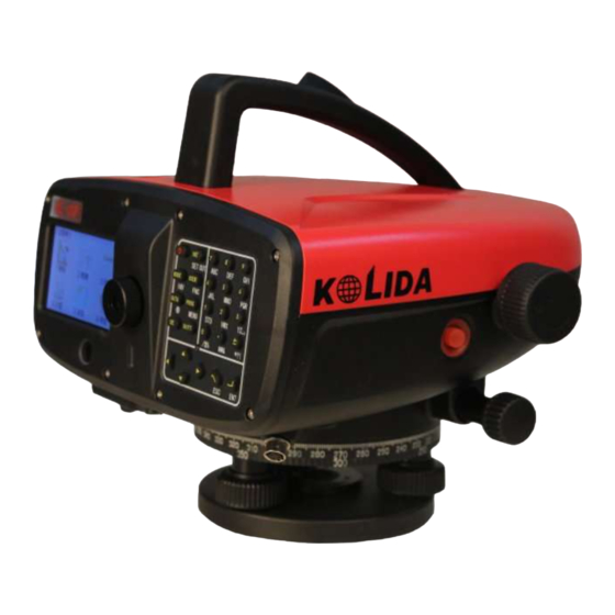
1. BRIEF INTRODUCTION 1. 1 Appearance 1 ON/OFF Key 2 Eyepiece Cover 3 Eyepiece 4. Trigger Key 5 Focusing Hand Wheel Unit 6 Keyboard 7 Display Unit 8 Handle 9 Battery 10 Circle Bubble 11 U-disk Port 12 RS232 COMM Port 13 Infinite Horizontal Tangent Unit 14 Optical Lens 15 Horizontal Circle... -
Page 9: Features
Electric Bubble 1.3 Measuring Principle The staff code was saved in KL-03 as a reference signal. When measuring, the image sensor will catch the staff image in the sight of view as the signal, then compare it with reference signal inside. Then it will get the height of sight line and the horizontal distance. Please up-right the staff vertically. -
Page 10: Others
D. Rotate the telescope focusing screw to clear the image. The code staff and cross-line will not move according the eyes’ movement. 1.5 Others 1) Please check the i Angle of KL-03, the circular bubble on equipment and staff before: ① doing the field measurement... - Page 11 Darkness: Please use a flashlight to lighten the code on staff Measurement at bottom code: KL-03 is available to aim at the position lower than 0 in a little. The value will be minus. Measurement at the top code: KL-03 is available to aim at the bottom, but it will influence the accuracy for level.
-
Page 12: Optical Level
5) Aim at the target precisely by adjusting horizontal tangent 6) Check the bubble 7) Record the center height H of cross-hair on the staff Eg. H=2.586m When using the digital level, press trigger key after repeat the step 1-6, KL-03 will record the code and distance automatically. -
Page 13: Distance Measurement
1.6.2 Distance Measurement After the same steps 1 -6 of Chapter 2.2.1 Height Measurement. Upper cross-hair: 2.670 m, bottom cross-hair: 2.502 m Interval L: 0.168 m, based on the formula distance= 100 x L Distance d: 16.8 m 1.6.3 Angle Measurement The bottom horizontal disk can be the reference of angle measurement in 360°/ 400 gon, each 1 scale means 1 degree. -
Page 14: Operation
2. OPERATIONS 2.1 Operation Keys Power on: Press [ON/OFF] key shortly Power off: Hold [ON/OFF] key in 1s Trigger Key: Press trigger key to start measurement ☞ If you press the keyboard too hard, it might cause the vibration of equipment. The vibration might influence the compensation and the accuracy for measurement. - Page 15 Press [INV] again to back for normal mode, the value will be minus. Press [SHIFT] [MODE] to enter. [FNC] Activate the other functions on KL-03. Press [SHIFT][USER] to enter. [MENU] Menu setting. Press [SHIFT][PROG] to enter. ] is for illumination. Press[SHIFT][DATA] to activate.
-
Page 16: Main Menu
[ENT] to start Option 3: Press the number 1-6 to start ☞ Note: In KL-03, you can enter any interface by one of those start-up methods.The following manual will only select one to explain. Main menu shown as below:... - Page 17 View/Add/Delete job Code View/Add/Delete code Line View/Add/Delete line Line Tolerance View/Add/Delete line tolerance Memory Memory Info Check the line/known pt/job...etc Management which store in internal memory Memory Format Formatting memory Export Data Export Job Export the job data to u-disk or Bluetooth device Expt Line 3 Adjust...
-
Page 18: Measurement
3. MEASUREMENT 3.1 Height Press [Meas], [Height] to enter the height measurement interface. Input BS height by manual, press Trigger Key to measure. Press [OK] to check the result. -
Page 19: Stake Out
3.2 Stake Out Press [Meas], [Stake Out] to enter the height measurement interface. Input or search the existed back-sight point and height. Press Trigger Key to measure this point. You can choose Elevation, Difference Height or Stadia stake out after press [OK] If the height is existed in the current job, it will display on the blank of S.O Pt Height automatically. -
Page 20: Line Meas
3.3 Line Meas Press [Meas], [Line Meas] to enter the line measurement interface. You can enter the sub-menu in following methods: 1) Click the corresponding area to activate 2) Use[↑↓] to move the cursor and press [ENT] to confirm 3) Press numeric keyboard, for example [1] for quick start The line tolerance has been settled in Level 1-4 Measurement. - Page 21 The below form has listed the measure method and tolerance for Level 1/2/3/4 Measurement. Line Measurement Method Line Tolerance (unit: m) Level 1 aBFFB Total Stadia Diff: 3 Max. Stadia:30; Min. Stadia: 4 Max. Sight Ht:2.8; Min. Sight Ht: 0.65 dH Tolerance: 0.0004 B-B/F-F: off B-F Diff: 1...
- Page 22 Level 4 BBFF Total Stadia Diff: 10 Max. Stadia:100; Min. Stadia: 3 Max. Sight Ht: off; Min. Sight Ht: off dH Tolerance: 0.005 B-B/F-F: off B-F Diff: 3.0 Turn Diff: off User-defined Line Measurement This user-defined line measurement is saved by station. It will save the data after pressing [OK].
- Page 23 (3) Set the line Choose 2.Line to create a new line. Name: Input the line name. Meas. Type: BF / aBF / BFFB / aBFFB/BBFF Start Pt: Start point H0: Height for start point. Measure Type Odd Station Even Station aBF (Alternate BF) BFFB BFFB...
- Page 24 Fine Mode: On one hand, the equipment will monitor the distance between ends of staff and the record. The code at the edge might decrease the accuracy of leveling. The equipment will warning the user when the distance to the ends is less than 50cm. When activate Fine Mode, the equipment will set the invar staff in 3m.
- Page 25 (6) Start After input all the configuration, press [Trigger Key] to start measurement. BS Point NO: Back-sight point (start point) number. If the line is continuously, it will show the name of last station. It will display the height, and distance on screen. Repeat measurement is available. Press [OK] to confirm and measure the fore-sight point.
-
Page 26: Com/Bluetooth
Choose [1.COM Port]. Setting the configurations, then press [Next] to next page. Comm port is only for remote control measurement, not for data transmission. 3.4.2 Bluetooth Choose [2.Bluetooth]. Set the password for Bluetooth connection. The data can be transferred from KL-03 to PC by Bluetooth or U-disk. -
Page 27: Measure Mode
3.5 Measure Mode Under measurement interface, press [MODE] key to set the measure mode. Measure mode: Fine: Fine measurement. (n=1) Fine Repeat: Repeat the fine measurement in n times, n ≤99, until pressing [stop]. The fine repeat mode will increase the quality of data, especially under the unstable environment. -
Page 28: Function
go on until the settled measure times. The equipment will check the standard deviation in each steps. Min. Meas Times: 2-99 Max. Meas Times: 2-99 Deviation/20m: the average standard deviation in 20m Eg. Measure Range= 60m, Standard Deviation/20m = 0.007m Standard = Deviation x 60m = 0.0021m In 60m, the max. -
Page 29: Code
3.6.3 Code In Code page, the user can input code in below method: 1) choose the code from code list when the codes are existed in memory previously. 2) Search or input the codes, press [Add] to add a new code, then press [Save] to confirm 3.6.4 Pt N Input the name of start point and interval for automatic increasing point number. -
Page 30: Input
number input by manual will increasing from the start point. 3.6.5 Input When the target distance is less than 1.8m, the equipment will not available for digital leveling. Please use optical level mode to finish the job by inputting data by manual. Please notice that: 1) Consider the correction of earth curvature 2) Whether the value of inverse measurement is negative... -
Page 31: Data
4. DATA The Data Page can input, edit and copy the data in other format. All the measured data can seamless export to PC by U-disk or Bluetooth device. Press [2] or click the icon directly to enter. 4.1 Edit Data Edit, create, view or delete the data of measure point, known point, job, code, line, line tolerance. -
Page 32: Known Point
Press [Next] or navigation key to check the next page. Press [Last] to check the last point. 4.1.2 Known Point The data of known point should including the coordinate (X, Y, H) or only Height. Choose the job and point name. (“*” means “all”) to search. -
Page 33: Code
User can delete or add a new job in this function. 4.1.4 Code The user can check the code list, with maximum 8 property in 2 pages. The code list will store at a fixed file. All the job on this equipment can view, edit or delete this code list. Del: Delete the existed code Add: Add a new code into list. -
Page 34: Line Tolerance
4.1.6 Line Tolerance The user can view, edit and add the tolerance standard in this interface. The tolerance standard will store at a fixed file. All the job on this equipment can view, edit or delete it, with maximum 10 property in 2 pages. -
Page 35: Memory Management
4.2 Memory Management Check the information, storage situation and memory formatting. 4.2.1 Memory Info The user can check the job name, existed quantity of lines and known points. 4.2.2 Memory Format The formatting password is 519... -
Page 36: Export Data
4.3 Export Data The equipment can export the data by U-disk or Bluetooth device. 4.3.1 Export Job If export to U-disk, the user should select the job, data type and export menu. Click [Expt] to confirm and export data. It will create a folder named “DEFAULT” (or the other job name) under menu “DL200”... - Page 37 Using export to Bluetooth device as an example, after select the job, line name and data type, click [Find] to search a new Bluetooth device for transfer. Then press [Next] to confirm. Input the folder’s name by manual, press [Expt] to export data into device.
-
Page 38: Adjust
5.1 Check KL-03 has two kinds of adjust method. The first is “A X B X” and the second is “ A X X B”. A/B means the code staff, X means the position for equipment. Press [1] or click it directly to... - Page 39 Steps: 1)Job: click Job column or press [1] to confirm the job name. 2)Method: choose the checking method “AXBX” or “AXXB”. The users can name the staff in this page. Each method including 2 ways: AXBX: Center measurement and Kukkamäki method. AXXB: Förstner and Nbauer method.
- Page 40 5.1.1 AXBX Method 1) Center Measurement. Set the equipment between the two code staffs of 30m. Then move the equipment closer to Staff B. As picture shown: The distance should meet the following conditions: A. Station 1, the equipment should set in the center, the deviation should within ±1m, without focusing.
-
Page 41: Dual-Axis Adjust
Set the equipment at 1/3 between two staffs. The distance between two staffs should be 40m-60m. It also need to meet the following conditions: A. Station 1: 0.2 x D < DIST_A1 < 0.4 X D B. Station 2: 0.2 x D < DIST_B2 < 0.4 X D 2) Näbauer Method Set the equipment outside the staff, a is about 15m-20m. - Page 42 1)Adjust and leveling the equipment. 2) Open the E bubble 3) Read the compensate value X1 and Y1 4) Rotate the equipment in 180°, read the value X2 and Y2. Deviation of X = (X1+X2)/2 Deviation of Y = (Y1+Y2)/2 If the deviation is over ±15”, please adjust the dual-axis by following steps: 1) Adjust and leveling the equipment 2) Open the dual-axis adjust page.
-
Page 43: Reticle Cross-Hair
5.3 Reticle Cross-hair If the tilt error is over 3mm/each 30m, the user need to adjust the equipment. 1. Adjust the screws by allen key slowly to correct the value 2. Check the tilt error: compare the digital value with optical value, the difference is the error value. -
Page 44: Calc
6. CALC 6.1 Line Adjustment In Line Adjustment program, the user can do the adjustment for single line. It can define any two points as occupied point with known height. This program will calculate the closure error and adjust it. Press [4.CALC] under main menu to enter the line adjustment page. - Page 45 Pt 1: is the first point in this line, the user can choose an arbitrary point. Pt 2: is the end point in this line, it should be an arbitrary point which can makes this line into correct order. The order of Pt 1 to Pt 2 should be accordance with the line. Pt 1 Ht/ Pt 2 Ht is the height for these two points.
-
Page 46: Set
7. SET 7.1 Quick Set Press [1.Quick Set] by numeric key or click on screen to enter this setting page. In Quick Set interface, the user can change the settings for Atmosphere correction, earth curvature, user key and decimals. 7.2 Complete Set In Complete Set page, it divide into four parts. - Page 47 7.2.1 Meas Setting Decimals: the digits for display and input Unit: m or ft Format: DL200 Earth Curvature: On or Off Staff Invert: On or Off Atmos Correction: On or Off Atmos Constant: User input the atmosphere constant by manual. 7.2.2 System (1) Sound Setting The sound setting including voice switch, sound switch and volume.
- Page 48 (2) Back Light The back-light setting including keyboard and bubble back-light, LCD auto back-light control. (3) Other Setting Date: Display and set the system date. The format is Year/Month/Day Time: Display and set the system time in Hour/Minute/Second User Key: User-defined for [User] key. It can settles View/Code/Pt N/Input/E...
- Page 49 User Manual: On or Off Auto Off: On or Off, if on, select the off time Sleeping Time: Select the sleeping time without operation. Press any key to wake up. Data Export: by U-disk or Bluetooth I Angle: display the current i angle. It can be modified by manual.
-
Page 50: E Bubble
7.2.4 Factory Mode Please notice that all the data will be recover under factory mode. 7.3 E bubble... -
Page 51: Help
8. HELP 8.1 User manual In Help page, the user can check the key note and adjust explanation in detail. 8.1.1 Key Note 8.1.2 Adjust Explanation... -
Page 52: Specifications
9. SPECIFICATIONS Height Measurement With Invar Staff 0.3mm (ISO17123-2) With Standard 1.0mm Optical Level 2.0mm Standard Deviation 5mm/10m Distance Measurement Accuracy D≤10m:10mm;D>10m:D*0.001 1.8m – 110m Digital Distance Range ≥0.6m Optical Height 1mm/0.1 mm/0.01mm optional Min. Display Distance 0.01m Measure Time 3 seconds Measure Mode Fine, Fine Repeat, Average, Median... - Page 53 Accuracy 0.2” Display 3.0inch TFT LCD 400*240, Colorful Touch Screen Tilt Error Automatic Value Correction Earth Curvature ON/OFF Dimension L×B×H 230mm×225mm×203mm Weight (Including battery) 3.1kg Working Temperature -20ºC - +50ºC Storage Temperature -40ºC - +70ºC Protection IP56 Battery Lithium 3100mAh/7.2V Working Time Over 20hrs...
-
Page 54: Correction Statement
Correction Statement Earth Curvature: E = X 2 / (2R) X = measured distance, R = 6378000m(Diameter of earth) Refractive index: K = rk* (X*X)/(2R) rk= refractive constant, X= measured distance. I Angle = arctan[(A1-B1+B2-A2) / (d1-d2+d3-d4)] A1, B1, B2, A2 = height of staff d1, d2, d3, d4 = the distance which relative to the height of staff Total Stadia difference = ∑...
Need help?
Do you have a question about the KL-03 and is the answer not in the manual?
Questions and answers