Table of Contents
Advertisement
Quick Links
Advertisement
Table of Contents

Related Manuals for Kolida K3 IMU


Summary of Contents for Kolida K3 IMU
- Page 1 K3 IMU KOLIDA K3 IMU Positioning System User Guide - 1 -...
-
Page 2: Table Of Contents
K3 IMU Contents Contents ............................- 2 - ChapterⅠPreface ......................... - 4 - §1.1 Introduction ......................... - 4 - §1.2 Applications ......................... - 4 - §1.3 Main Features ......................- 5 - ChapterⅡ Hardware Introduction ....................- 7 - §2.1 Bottom Components ....................- 8 - §2.2 Indicator and buttons .................... - Page 3 K3 IMU Appendix A KOLIDA K3 IMU technical specifications ............- 38 - Appendix B Technical Terms ..................... - 39 - FCC Statement ........................... - 40 - - 3 -...
-
Page 4: Chapterⅰpreface
GNSS receivers and Total Stations, etc. To know more about KOLIDA, please visit our official website http://www.kolidainstrument.com/. In the guide, we'll show you how to operate the K3 IMU RTK system as well as the accessories. We recommend you to read the guide carefully before getting started. -
Page 5: Main Features
A Lightest Receiver, Comfortable Experience K3 IMU is an ultra light GNSS receiver that leaves the competition behind. Its total weight is only 0.69 kg including battery, 40% even 50% lighter than a traditional GNSS receiver. The light-weight design reduces surveyor’s fatigue, increase their mobility, is especially helpful to... - Page 6 410MHZ-470MHZ. “Farlink” technology improves the signal-catching sensitivity from -110db to-117db, so K3 IMU can catch the very weak signal from a base station far way. Internal Web UI management Embedded Web UI management platform supports WIFI and USB mode connection.
-
Page 7: Chapterⅱ Hardware Introduction
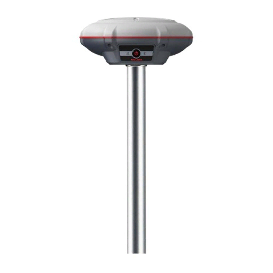
ChapterⅡ Hardware Introduction Reading this chapter, you can grasp the components, installation and the function of KOLIDA K3 IMU measuring system. The receiver is round and flat with height of 60mm and diameter of 137mm. It looks elegant, strong and durable. And it adopts a combination design of voice and buttons, easier to operate. -
Page 8: Bottom Components
K3 IMU §2.1 Bottom Components Speaker Serial number Label UHF antenna interface Battery indicator 5-Pin LEMO Port USB interface Component Description Mode setting and working status prompt Speaker SN label Apply for a registration code, Bluetooth ID Battery indicator Real-time indication of battery level. -
Page 9: Indicator And Buttons
Indicator §2.3 Check the remaining power When K3 IMU is charging, the corresponding light flashes before charging to the corresponding power. Press the power button once, the current battery level will show several lights. For example, when the battery is fully charged, the four lights of 25%, 50%, 75%, and 100% are all green on. -
Page 10: Check And Switch Working Mode
Press and hold the power button for about 20 seconds and pass over the foregoing states (power off, start to set work mode and self-check), K3 IMU will get into factory reset progress with voice message saying “start to restore factory default”, at this moment, release power button, the instrument will perform factory reset automatically. -
Page 11: Chapterⅲ Web Ui Management
Because of using the smart embedded Linux operating system and KOLIDA intelligent cloud technology, the web UI allows users to configure and monitor the status of K3 IMU in real-time. The accessing way is not only by WIFI connection, but also can be USB mode. -
Page 12: Access By Usb
Password: admin §3.3 Access by USB On this mode, the type-C USB port of K3 IMU works as an Ethernet port, then internal web UI shall be accessed via USB cable connection with computer.A corresponding driver is required to install to the computer, then this function could be activated. You can contact with KOLIDA technician for the driver and support. -
Page 13: Web Ui Main Interface
K3 IMU §3.4 Web UI main interface After login the Web UI management of K3 IMU by WIFI or USB connection, the main interface appears with displaying configuration items and positioning. As shown at following figures. In the Web UI home page, the configuration items are listed at left side. And the positioning informaiton including coordinates information and satellites are diplayed at right side. -
Page 14: Status
System Information, Work Status and Position Information are listed under Status menu. System Information In this page, all the information of K3 IMU is diplayed such as serial number, hardware ID, MAC address, firmware version and so on. - 14 -... - Page 15 K3 IMU Work Status The physical state of K3 IMU such as working mode, datalink, host temperature, remaining power and the free memory is obtained from this page. Position Information In this page, users can be clear at a glance on current position information and satellite information.
-
Page 16: Configuration
The registration for receiver working mode setting can be completed. If K3 IMU is expired, please provide the serial number of your K3 IMU for us to apply for another available code, then input the code into the blank or register the receiver online. - Page 17 K3 IMU K3 IMU allows users to setup the working mode and datalink from this Web UI that only need the mobile phone or tablet PC is able to connect the wifi hotspot of K3 IMU. Work Mode: There are Rover, Base and Static contained in this dropdown list.
- Page 18 Base Setup (works as an internet base station) When K3 IMU works as Base station, the basic configuration for base can be setup in this page. Users can input the correct coordinates or capture a current position for the base. Also users can define what kind of correction format is transmitted.
- Page 19 K3 IMU Antenna Height: This is the value for height of antenna while surveying. Measuring Method: Here provides several methods for measuring the antenna height such as carrier phase center, slant height, antenna edge, height plate and to the bottom.
- Page 20 Power: Configure the receiver to use the power saving mode or not. USB: The Type-c interface of K3 IMU is set to USB disk and network interface mode at the same time, no need to set up it for K3 IMU.When connected to the computer, you can open internal memory and runweb Ui at the same time for K3 IMU.
-
Page 21: Satellite Information
K3 IMU §3.4.3 Satellite Information The “Satellite Information” provides all kinds of tables, graph and the skyplot to view the information of tracking satellites. And it is allowed to configure to use which satellite in constellation on/off page by checking on the corresponding box. -
Page 22: Data Record
§3.4.4 Data Record The “Data Record” performance is mainly used to configure all the parameters for receiver in static mode. Much more operations can be done on KOLIDA K3 IMU such as storage path, interval, data format and data files download. - Page 23 K3 IMU. File Interval: This is used to defined the data storage time for the static file. Data Format: Here are 3 options to selected for KOLIDA K3 IMU to store what kind of format data, STH, Rinex2.0 and Rinex3.0.
-
Page 24: Data Transfer
CAUTION: do not change the default value in this page for each item, if you want to change the settings, please contact with KOLIDA technician for further support. In the dropdown list of data flow, there shows 4 items for selection. - Page 25 And there are Caster and Server working mode for this performance. Caster: If this working mode is selected, KOLIDA K3 IMU will be a client to upload the data to a specify server if it connects to the internet by WIFI. Input the specified IP and port for server, and the data format what is uploaded.
- Page 26 K3 IMU Server and NTRIP Caster. Data Flow Config In this page, users can optionally to configure the content and the update rate of data flow that to output or not to output what kind of data format. Click on the dropdown list for each data format to define the update rate...
-
Page 27: Network Config
Web UI. Check the box of AP in Work Mode to enable the WIFI hotspot for KOLIDA K3 IMU, and define the SSID, password, encryption method and broadcasting channel for WIFI connection. - Page 28 Bluetooth, discoverable or not, the PIN code, and the connection devices in following table. Port Forwarding This page is mainly used to view and configure the internet transmission port for KOLIDA K3 IMU, customize and debug receiver. - 28 -...
- Page 29 This is mainly used to view and configure the parameters for router, only under the condition of customize and debug receiver. NOTE: Usually we will keep the default setting in this page, if you would like to modify it, please contact with KOLIDA technician for more supports. - 29 -...
-
Page 30: Radio Config
Data Baud Rate: This represents the rate of data transmission port of internal radio. The rate should be the same in both Base and Rover. In general, the data baud rate of KOLIDA radio module has been unified to be 115200, keep it as default. -
Page 31: Firmware Update
Update the latest firmware for receiver or for corresponding modems can be done in “Firmware Update”. Firmware Update This page displays all the information of the firmware which current installed on KOLIDA K3 IMU, and allows to update the latest version firmware for receiver. To get latest version firmware please contact with KOLIDA technician. -
Page 32: Track Manage
This page is used to update the firmware for corresponding modem such as OEM board, radio module and sensor. §3.4.9 Track Manage K3 IMU supports to record the track while doing measurement, and upload the data onto the server. Parameter Setting... - Page 33 K3 IMU Record Config: Check on the box of “Record Enable” to activate track recording function, and choose a proper recording interval in dropdown list of “Record Interval”. Echo Config: This configuration dialog is used to upload the recording data to a server in real-time.
-
Page 34: Coordinate System(Reserve)
K3 IMU §3.4.10 Coordinate System(reserve) K3 IMU allows users to setup the local coordinate system on internal web UI management. The instrument would output the local coordinates according to this coordinate system. §3.4.11 Online Service (reserve) This function is to upload the data onto a server real-time, including Navigation data, raw observation data, correction data, SIC observation data and open SIC observation data. -
Page 35: User Management
K3 IMU §3.4.12 User Management This page is used to manage the authority of login Web UI for users, including the username, password and add users. §3.4.13 System log In this page, users can get help and check the log book of receiver (the log book can help to backtrack the working status of receiver). -
Page 36: Chapterⅳ Accessories
ChapterⅣ Accessories §4.1 Instrument Case The instrument case for KOLIDA K3 IMU contains two layers of packing: the inner layer is filled with anti-collision foam, the host and other accessories can be dispersed and embedded; the outer layer is a hard instrument case, sealing-strong, wear-resistant anti-wrestling. Compact, durable, can effectively prevent the impact, easy to clean. -
Page 37: Differential Antenna
§4.3 Differential Antenna UHF Antenna The UHF differential antenna is required to install to the interface at the bottom of receiver if KOLIDA K3 IMU is set up into internal UHF mode. §4.4 Cables Type-C data cable The cable is to connect the receiver and the computer to transfer static data and upgrade the host firmware. - Page 38 K3 IMU Appendix A: KOLIDA K3 IMU technical specifications - 38 -...
- Page 39 K3 IMU Appendix B Technical Terms Ambiguity: unknown quantity is the integer number of cycles of the carrier phase measured from the satellite to the receiver. Baseline: The connection line of the two measurement points, on which to receive GPS signals and collect observation data simultaneously.
- Page 40 K3 IMU L-band: The radio frequency range of 390-1550MHz. Multipath error: the positioning error caused by the interference between two or more radio signal propagation path. Observing session: the use of two or more receivers at the same time to collect GPS data period.
Need help?
Do you have a question about the K3 IMU and is the answer not in the manual?
Questions and answers