Table of Contents
Advertisement
........................................................................................................................................6
1. Features..................................................................................................................................................6
2. Precautions..............................................................................................................................................7
3. Nomenclature........................................................................................................................................9
4. Key Functions......................................................................................................................................11
5. Character Entry....................................................................................................................................13
6. Display Symbol...................................................................................................................................14
7. Mode Configuration...........................................................................................................................14
1. Unpacking and Storage of Instrument..............................................................................................18
2. Setting the instrument up................................................................................................................20
3. Battery dismounting, information, recharging.................................................................................21
4. Reflector Prisms..............................................................................................................................22
5. Mounting and Dismounting instrument from tribrach....................................................................22
6. Eyepiece adjustment and object sighting........................................................................................23
7. Power on/off and preparation for measurement............................................................................23
7.1 Power on/off..................................................................................................................................23
7.2 Vertical Angle Tilt Correction......................................................................................................23
7.3 Setting Instrument Options..........................................................................................................25
7.4 Setting Instrument Constant.........................................................................................................27
7.5 Setting Date and Time..................................................................................................................28
7.6 Explanations...................................................................................................................................28
8. Angle Measurement......................................................................................................................30
8.1 Measuring Horizontal Angle between Two Points...................................................................30
8.1.1 Example Measuring Horizontal Angle between Two Points...............................................31
8.2 Setting Horizonal Angle to a Required Value........................................................................32
8.2.1 Use HSET function to set a required direction Value ..........................................................32
8.2.2 Use HOLD to set a required direction value.....................................................................32
8.3 Horizontal Angle Display Selection (right/ Left)......................................................................33
CONTENTS
............................................................................30
www.kolidainstrument.com
............................................18
1
Advertisement
Table of Contents

Related Manuals for Kolida Total Station KTS-462R10L


Summary of Contents for Kolida Total Station KTS-462R10L
-
Page 1: Table Of Contents
CONTENTS FOREWORD ............................6 1. Features…...............................6 2. Precautions..............................7 3. Nomenclature............................9 4. Key Functions............................11 5. Character Entry............................13 6. Display Symbol...........................14 7. Mode Configuration...........................14 PART 1 PREPARATION FOR MEASUREMENT ..........18 1. Unpacking and Storage of Instrument....................18 2. Setting the instrument up……….......................20 3. Battery dismounting, information, recharging.................21 4. - Page 2 8.4 Horizontal Angle Repetition..................34 8.5 Slope in %........................35 9. Distance Measurement.........................36 9.1 Settings for Distance Measurement................37 9.2 Laser Pointer and Laser Plummet................39 9.3 Distance and Angle Measurement.................40 9.4 Review of Measured Data..................41 9.5 Output Data to a computer....................42 10. Coordinate Measurement......................43 10.1 Input Instrument Station Data..................44 10.1.1 Reading in Registered Coordinate Data..............45 10.2 Azimuth Angle Setting....................46...
- Page 3 17.3 Setting-out Line (Line)....................84 18. Point Projection......................86 18.1 Defining Baseline......................86 18.2 Point Projection......................87 19. Road Design and Setting-Out....................88 19.1 Road Design......................88 19.1.1 Define Horizontal Alignment..............88 19.1.2 Edit Alignment……..................93 19.1.3 Define Vertical Curve..................94 19.1.4 Edit Vertical Curve..................96 19.1.5 Import Horizontal Alignment................97 19.1.6 Import Vertical Curve..................98 19.1.7 Receiving Horizontal Alignment Data............98 19.1.8 Receiving Vertical Curve Data.............100...
- Page 4 20.2.1 Input Known Point Coordinate..............124 20.2.2 Known Coordinate Data Import..............125 20.2.3 Known Coordinate Data Export..............126 20.2.4 Receive Coordinate Data from Computer..........126 20.2.5 Sending Known Point Data to Computer..........127 20.2.6 Clearing Coordinate Data from Memory……..........128 20.3 Input Codes......................128 20.3.1 Codes Import....................129 20.3.2 Receive Codes..................130 20.3.3 All Clear………..................130 20.4 Disk Mode....................131...
- Page 5 24.5 Vertical Index Difference Compensation..............158 24.6 Adjustment of Vertical Index Difference (i angle) and Vertical Angle 0 Datum..159 24.7 The Adjustment of Horizontal Axis Error Correction..........161 24.8 Optical Plummet......................162 24.9 Instrument Constant (K).....................163 24.10 Parallel between Collimation Line and Emitting Photoelectric Axis......164 24.11 Reflectorless EDM....................164 24.12 Tribrach Leveling Screw....................165 24.13 Related Parts for Reflector………...................165...
-
Page 6: Foreword
This manual is applicable for KOLIDA Total Station KTS-462R10L. 1. FEATURES 1. Complete Function KOLIDA KTS-462R10L has complete surveying program and the functions of data record and parameter setting, is suitable for professional survey and construction survey. 2. Secure Digital memory card(SD card)... -
Page 7: Precautions
2. PRECAUTIONS 1. Never place instrument directly on the ground,as sand or dust may cause damage to the screw holes or the centering screw on the base plate. 2. Before carry on the measurement, we need to have an overall check with the inrsrument, such as: battery, parameters, and initial settings. - Page 8 Warning: Continuously looking straight at the laser beam is harmful. Prevention: Do not stare at the laser beam, or point the laser beam to others‟ eyes. Reflected laser beam is a valid measurement to the instrument. Warning: When the laser beam is shooting at prism, mirror, metal surface or window, the reflected laser beam is also harmful to eyes.
-
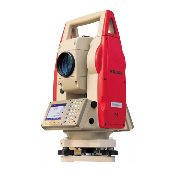
Page 9: Nomenclature
3. NOMENCLATURE Collimator Objective Lens Battery Plate Level Battery locking Horizontal Clamp Screw Screen Horizontal Tangent Scew SD Card Reader Mini USB port Base Plate www.kolidainstrument.com... - Page 10 Telescope Focusing Knob Center Mark Eyepiece Vertical Clamp Screw Vertical Tangent Scew Keyboard Communication Port Circular Level Tribrach Fixing Scew Leveling Screw www.kolidainstrument.com...
-
Page 11: Key Functions
4. KEY FUNCTIONS Alpha-Numeric Switch Input Target Height Back Space Number Key Star Key Power Direction Key Enter Soft Key F1-F4 Help · Power ON / OFF Key Power ON :Press POWER for 2 seconds Power OFF :Press POWER for 3 seconds ·... - Page 12 1. Enable target-height inputting in staking-out, missing line, and remote measurement. 2. Enter RECORD menu. Show KOLIDA web address HELP Cancel previous operation and return to previous screen Confirm to entry or save data on that line and move the cursor to the next line.
-
Page 13: Character Entry
Move cursor to the left / Select another options view the next page in data list 5. CHARACTER ENTRY Job names, data numbers, codes, etc are entered to KTS-462R10L using letters of alphabet and numerals. Change between alphabetic and numerical entry by pressing IM key. An is displayed on the right side of the screen when in alphabet entry mode. -
Page 14: Display Symbol
6. DISPLAY SYMBOLS Some symbols are used in MEAS mode. Their meanings are presented below. Symbol Meaning Prism constant Atmospheric correction Zenith angle( Zenith 0° ) Vertical angle( horizontal 0° / horizontal 0° ± 90° ) % Slope in % Slope distance Horizontal distance Height difference... - Page 15 1. Mode Diagram MEAS MENU CNFG www.kolidainstrument.com...
- Page 16 2. Menu List ① MEAS mode menu Name Function DIST Distance measurement Display switch between distance and coordinate 0SET Set horizontal angle to 0 HSET Set known horizontal angle Select horizontal angle right/Left Horizontal angle repetition measurement HOLD Horizontal angle Hold/Release ZA/%...
- Page 17 ② REC Mode Menu Name Function Stn data Occupied station data recording Back sight data Record backsight bearing angle and coordinate data Angle data Angle measurement data recording Dist data Distance measurement data recording Coord data Coordinates measurement data recording Dist + Coord.
-
Page 18: Part 1 Preparation For Measurement
PART 1 PREPARATION FOR MEASUREMENT 1. UNPACKING AND STORAGE OF INSTRUMENT · Unpacking Instrument Place the case lightly with the cover upward, and unlock the case, take out the instrument. · Storing Instrument Cover the telescope well, place the instrument into the case with the vertical clamp screw and circular level upward (Objective lens toward tribrach), tighten the vertical clamp screw and lock the case. - Page 19 4. Leveling by the plate level ① Rotate the instrument horizontally by loosening the Horizontal Clamp Screw and place the plate level parallel with the line connecting leveling screw A and B, and then bring the bubble to the center of the plate level by turning the leveling screws A and B. ②...
- Page 20 3) Use circular vial to roughly level the instrument Adjust length of three legs of tripod, make the circular vial bubble of the instrument in the middle. 4) Use plate vial to level the instrument accurately. ①Rotate the instrument horizontally by loosening the Horizontal Clamp Screw and place the plate vial parallel to the line connecting leveling screw A and B, and then bring the bubble to the center of the plate vial by turning the leveling screws A and B.
-
Page 21: Battery Dismounting, Information, Recharging
Unique Mini prism system allows to be set up at corners that are hard to reach. Illustrated are the prism manufactured by KOLIDA: www.kolidainstrument.com... -
Page 22: Mounting And Dismounting Instrument From Tribrach
5. MOUNTING AND DISMOUNTING INSTRUMENT FROM TRIBRACH Dismounting · When necessary, the instrument can be dismounted from tribrach. Loosen the tribrach locking screw in the locking knob with a screwdriver. Turn the locking knob about 180 degree counter-clockwise to disengage anchor jaws, and take off the instrument from tribrach. Directing Stub Anchor Jaw Directing Slot... -
Page 23: Power On/Off And Preparation For Measurement
7. POWER ON/OFF AND PREPARATION FOR MEASUREMENT 7.1 Power ON/OFF PROCEDURE · Power ON Operation Display Note After power on, instrument process self-check as left. Press SD Card Connected Checking the inserted SD card POWER Home Page Date 2015/07/28 Time 17:18:35 After Self-check, Home Page shows up. - Page 24 PROCEDURE Setting Tilt Correction Operating Procedure Operation Display MEAS(1/3) 1) Turn on the machine, enter MEAS screen. POWER 273°18′15″ 150°18′15″P1 DIST 0SET HSET Home Page Date 2015/07/28 Time 17:18:35 Ver. 20150415 2) Press ESC to enter status screen. Type KTS-460R6L K76400 A:/JOB.JOB MEAS...
-
Page 25: Setting Instrument Options
Steps Leveling instrument Operation procedure Display Single Axis 1) If instrument tilts over correction range, system launch tilt correction function. X-ON XYON Single Axis 2) Leveling the instrument according to the related chapter until the E-bubble centered in the tube X-ON: Only vertical angle be compensated XYON: Both horizontal and vertical angle are compensated... - Page 26 10 Min 20Min PowerOff 30Min N-E-Z * Coord. E-N-Z 0.1″ ; 1″* Angle Resolution 5″ ; 10″ Distance Resolution 0.1mm 1 mm * ON * Key Beep ON * Angle Beep Table 2: Settings Parameters Option(*:Factory Setting) 1200 b/s * ; 2400 b/s 4800 b/s ;...
-
Page 27: Setting Instrument Constant
DEG(360 degrees) * Angle GON(400 gon) MIL(mil) m(meter) * Distance ft(feet) Feet International Feet USA Feet 7.4 Setting Instrument Constant ·Refer to “22.8 Instrument Constant (K)” to get the instrument constant value. Set it as following: PROCEDURE Operating Procedure Operation Display Common Setting Reflect... -
Page 28: Setting Date And Time
The Additive Contant is effective under Prism mode only (measuring distance with prism). 7.5 Setting Date and Time · It is possible to set or revise the date and time displayed in the “Status Screen”. PROCEDURE Operating procedure Operation Display Settings(1/2)... - Page 29 Elimination of parallax Parallax is the relative displacement of the target image with respect to the reticle when the observer‟s head is moved slightly up and down or to the sides while looking through the telescope. Parallax will introduce reading errors and must be eliminated before observations are taken. Parallax can be removed by refocusing the reticle.
-
Page 30: Part 2 Basic Measurements
PART 2 BASIC MEASUREMENTS · This section explains the angle measurement, distance measurement, and coordinate measurement which can be performed in MEAS mode. · Measurement data can be recorded in the internal memory. For the recording method, refer to “19. Recording in Record Mode.”... -
Page 31: Example Measuring Horizontal Angle Between Two Points
PROCEDURE Operating Procedure Operation Display MEAS(1/3) 1) Press 0SET on the first page of the “MEAS Mode Screen”. 0SET 0SET H Angle? It asks “0SET H Angle?” YES NO MEAS(1/3) 2) Press F3 YES, the horizontal angle of the Press F3 collimation direction is set to 0°00′00″. -
Page 32: Setting Horizonal Angle To A Required Value
8.2 Setting the Horizontal Circle to a Required Value 8.2.1 Use HSET function to set a required direction value · It allows you to set the instrument sight direction to any required direction value. PROCEDURE Operating Procedure Operation Display Set H Angle 1) After sighting the target, from the MEAS mode 0°... -
Page 33: Horizontal Angle Display Selection (Right/ Left)
Operating Procedure Operation Display Allocate the MEAS(2/3) function 1.560m keys to 1) Under MEAS mode screen, Display the HOLD 1.240m function. 0.062m display 92° 36′ 25″ HOLD 30° 25′ 18″ REP. HOLD ZA/% Hold H Angle HOLD Current Value 2) Use the horizontal clamp and tangent screw to 92°... -
Page 34: Horizontal Angle Repetition
Press R/L, horizontal angle display switches from MEAS(2/3) [HAR] to [HAL]. 1.560m HAL = 360° - HAR 1.240m 0.062m Press R/L again, horizontal angle display switches 92° 36′ 25″ from [HAL] to [HAR]. 330° 00′ 00″ REP. HOLD ZA/% 8.4 Horizontal Angle Repetition ·... -
Page 35: Slope In
Repetition Sight at Take FS 3) After sighting the foresight point, press OK, foresight Reps Right screen is displayed. HARp 120° 20′ 00″ point 120° 20′ 00″ Press REST to cancel the measurement result and 0° 0′ 03″ measure again. REST Repetition Take BS... -
Page 36: Distance Measurement
MEAS 2) Press ZA/‴, use < > to switch between V%, 1.560m ± 90° . Zenith 0, vertical 0, 1.240m ZA/% 0.062m Press ZA/‴ again to switch vertical angle display 18.12% 30° 00′ 00″ again. REP. HOLD ZA/% ☆ Display range : within ± 100% ☆... -
Page 37: Settings For Distance Measurement
from the point which the crosshairs are sighting at. Therefore, it is recommended to verify that the laser is well collimated with the collimation axis. (Please refer to “22.10 REFLECTORLESS EDM”) ●Do not measure the same target with two total stations simultaneously. Red Laser Distance Measurement with Reflector Sheet The visible red laser beam can also be used to measure to reflector sheet. - Page 38 EXPLANATION Distance measurement mode · The following are the measuring time and the smallest distance displayed for each measurement method when a reflective prism is used. · Fine Measurement Accuracy :± (2 + 2PPM× D)mm (D is the measuring distance) Measuring time :...
-
Page 39: Laser Pointer And Laser Plummet
Prism constant Input the prism constant correction value suited to the reflector used. Select it with in following modes: Measurement mode Fine“r”, Fine A VG“n=1/2/3/4/5”, Fine“s”, Tracking Reflector Type NON-Prism, Sheet, Prism NOTE : Temperature entry range: -40° ~ +60° (step length 1‵) or –40 ~ +140℉ (step length 1℉)... -
Page 40: Distance And Angle Measurement
9.3 Distance and Angle Measurement · KTS-462R10L is able to perform angle measurement and distance measurement at the same time. · For recording measurement data, see “19. Recording Measurement Data”. · Check the following once more before measuring a distance: The KTS-462R10L is set up correctly over the station point. -
Page 41: Review Of Measured Data
MEAS(1/3) 120.00m 110.00m 50.00m 273°18′15″ 150°18′15″ 3) When distance measurement is completed, a DIST 0SET HSET short beep sounds, and the measured distance data (s), vertical angle (VA), and horizontal angle (HAR) DIST are displayed. Fine(r) 120.00m 110.00m 50.00m 273°18′15″ 150°18′15″... -
Page 42: Output Data To A Computer
PROCEDURE Operating Procedure Operation Display 120.00m 1) In MEAS mode, display the screen in which 110.00m [RCL] is registered, and press [RCL]. 50.00m 273°18′15″ 150°18′15″ 120.00m 2) Each time [D/C] is pressed, S (slope distance), H 110.00m (horizontal distance), V (height difference) are 50.00m displayed alternately. -
Page 43: Coordinate Measurement
DIST Fine[r] “1. Dist 120.00m 2) Use ▲▼ to select “1. Dist data,” and press ENT Data” 110.00m (or numeric key 1) to start distance measuring. 50.00m 273°18′15″ 150°18′15″ P1 STOP DIST 3) When distance measurement is completed, a Fine[r] 120.00m short beep sounds, and the measured distance 110.00m... -
Page 44: Input Instrument Station Data
· The following preparations are needed for coordinate measurement. Station point coordinates setting Azimuth angle setting · For the coordinate measurement method, see “7.4 Setting the Instrument Options”. 10.1 Entering Instrument Station Data · Before coordinate measurement, input instrument station coordinates, the instrument height, target height. -
Page 45: Reading In Registered Coordinate Data
3) Input the following items. REC Stn(1/4) N0 : 1234.688 N0,E0,Z0 (instrument station coordinate), Input station E0 : 1748.234 instrument height, target height. Z0 : 5121.579 data Each time you set an item, press ENT. Then press Stn : STN1 REC to record instrument station data. -
Page 46: Azimuth Angle Setting
2) Press ▲or▼ to align the cursor with the required SRCH point number which was read in. To use the point number to search for coordinate data, press [SRCH]. · Pt: Point number SRCH ▲ view previous data ▼ view next data turn back to previous page go to next page Coordinate... -
Page 47: Set Backsight Point By Angle
azimuth angle of the backsight station will be automatically set. 10.2.1 Set backsight point by Angle It allows you to set backsight azimuth angle by inputting angle value directly. Steps Operation procedures Display REC BS 1) Under coordinate measurement screen, use ▲▼ 1. -
Page 48: Set Backsight Point By Coordinate
10.2.2 Set backsight point by coordinate You can set backsight azimuth angle by inputting backsight coordinate, the machine calculates azimuth angle by station point coordinate and backsight coordinate. Operation Procedure Display REC BS 1. Angle 2.Coordina 2. Coordinate 1) In backsight setting menu, choose “2. Coordinate”. - Page 49 Station point coordinates: (N0, E0, Z0) Instrument height Prism height Height difference: Z The coordinate difference from the instrument center to prism center: (n,e,z) Unknown point coordinate: (N1,E1,Z1) N1 = N0 + n E1 = E0 + e Z1 = Z0 + instrument height + z – prism height ·...
- Page 50 120.00m 3) To record coordinate data in JOB, press REC. 110.00m Input the following items: 50.00m 1. Point number: target point number KOLIDA 2. Code: Codes or notes. Code After each entry .press ▼. SAVE CODE When the cursor is on the code line, code Quick Code function key show up automatically.
- Page 51 Coordinate 4) Sight at next target point and press OBS to begin 120.00m measuring. Press STN to access the station data 110.00m input screen, re-input the station data. OBS. 50.00m · The re-input station data will affect next 273°18′15″ measurement. So if the target height changes, enter *HAR 150°18′15″...
-
Page 52: Part 3 Advanced Measurement
PART 3 ADVANCED MEASUREMENT · This section explains resections, setting-out measurements, offset measurements, missing line measurements, REM measurements, area calculation, road design and others which can be performed in MEAS Mode. 11. SETTING-OUT MEASUREMENT · The setting-out measurement is used to set out the required point. The difference between the previously input data (the setting-out data) and the measured value can be displayed by measuring the horizontal angle, distance or coordinates of the sighted point. -
Page 53: Distance Setting-Out Measurement
11.1 Distance Setting-Out Measurement · The point can be found based on the horizontal angle from the reference direction and the distance from the instrument station. · From the menu mode, selecting “2. Set-Out” also can perform setting-out measurement. PROCEDURE Operating Procedure Operation Display... - Page 54 3) The screen will show as following: SO. H S.O H: the horizontal distance to the point to be set out. 89°45′23″ 150°16′54″ dHA: the horizontal angle to the point to be set out -0°00′06″ <--> REC. ← 15°34′28″ 4) Press <-->. The angle to the point to be set out is displayed on the first line.
-
Page 55: Rem Setting-Out Measurement
← 0°00′00″ ↑ 0.000m 9) Find the place where the distance is 0 m, that is 6.324 m the position of the point to be setout. 89°45′23″ 150°16′54″ <--> REC. 1.Observation 2.Set-Out 10) Press ESC to return to Setting-out measurement menu screen. - Page 56 MEAS(1/3) 2) The measurement result is displayed (If in 120.00m repetition mode, press STOP). 110.00m S: the slope distance to prism 50.00m 273°18′15″ ZA: the vertical angle to prism 150°18′15″P1 HAR: the horizontal angle to prism DIST 0SET HSET 1.Observation 2.Set-Out 3) Press S-O from the second page of MEAS mode.
-
Page 57: Coordinates Setting-Out Measurement
SO. HT -15.620m 7) Press REM to begin the setting-out, after 0.7 seconds, the distance between the setting-out data 89°45′23″ and the measured distance is displayed on the First 150°16′54″ line. (S-O. Ht). -0°00′06″ <--> REC. 8) After pressing <-->, then press REM, the ←... - Page 58 ·It is possible to perform coordinates setting out measurement by selecting “2. S-O” from Menu Mode. · It is possible to read the coordinate data previously entered and set it as the setting out coordinate. · To find the Z coordinate, attach the prism to a pole, etc., with the same target height. PROCEDURE Operating Procedure Operation...
- Page 59 3) After inputting station data, press OK to enter 1. Observation setting-out measurement menu. Select “4. Back “4.Back 2. Set-out sight sight data” and press ENT (or press numeric key 4 3. Stn data data” directly) to enter Angle Setting screen. 4.
-
Page 60: Distance Measurement Parameters Setting
9) Press ESC to return “Setting-Out” measurement 1.Observation menu screen”. 2.Set-Out To set out the next point, repeat the procedure from 3.Stn data step 4. 4.Back sight data 11.4 Distance Measurement Parameters Setting It is possible to set distance measurement parameters here, such as temperature, pressure, atmospheric correction, prism constant correction and distance measurement mode. -
Page 61: Offset Measurement
Method ②: Turn on Sensor, press F3 READ to read temperature and pressure Atmospheric correction value automatically, then calculate PPM out. Prism constant Enter the prism constant correction value for current prism Distance mode Press to select from following modes: Fine repetition, Fine N-time, Fine single, tracking Note: Temperature input range: -99.9°... -
Page 62: Single-Distance Offset Measurement
2. Angle offset measurement Install the offset point as close as possible to the target point to its left or right. 3. Dual distance offset measurement · Install the offset point A and B on a line extending from the target point, measure A and B, then enter the distance between B and the target point to find the target point. - Page 63 PROCEDURE Operating Procedure Operation Display MEAS(1/3) 120.00m 1) Sight the offset point then press DIST in the 110.00m DIST 50.00m MEAS Mode Screen. 273°18′15″ 150°18′15″ STOP MEAS(1/3) 120.00m 2) When the measurement is completed (during 110.00m repetition measurement, press STOP) the slope 50.00m distance from station point to offset point, vertical 273°18′15″...
- Page 64 6) Press REC to record the results. Set the following 10.00m items while referring to “17.1 Recording Distance 110.00m Measurement data.” 60.00m Pt: Point number (Target point number) CODE kolida Code (press CODE to read in code) SA VE SAVE R.HT CODE Tgt.h: Target height (press R.HT) R.HT Setting ·...
-
Page 65: Angle Offset Measurement
↓ offset point behind the target point ☆Re-observate the offset point: OBS. 12.2 Angle Offset Measurement · Install offset points for the target point on the right and left sides of and as close as possible to the target point. The distance from station point to offset point should be almost same with the distance from station point to target point. -
Page 66: Two-Distance Offset Measurement
OBS. The measurement result will be shown. 60.00m 273°18′15″ 150°18′15″ REC. OBS. REC/Distance 10.00m 110.00m 60.00m CODE kolida 4) Press REC to record measurement result. (See SA VE R.HT CODE “19.4 Recording Distance Measurement.”) REC. R.HT Setting Tgt. h 0.000m OFFS 1.Offset/Dist... - Page 67 ☆ NOTE: 1. The offset distance of Two-distance Offset Measurement depends on the distance between offset point 2 and target point on the line which consisted of target point, offset point 1and offset point 2. 2. It needs to measure the distance from the target point to the 2 target.
- Page 68 Offset/2D Take 1st o/s read 4) When observation has been completed, it displays 10.00m the “1 st Target Observation Result Screen.” The 110.00m coordinates of the 1 st are displayed. Then press 60.00m 273°18′15″ 150°18′15″ OBS. Offset/2D Take 2nd o/s read 10.00m 5) After pressing OK, the “2 nd Target Observation 110.00m...
-
Page 69: Missing Line Measurement
10) Press REC to input the Pt and code. 10.00m 110.00m Press R.HT to input Target height. 60.00m Press CODE to read in the recorded code in memory. CODE kolida SAVE R.HT CODE OFFS 1.Offset/Dist 11) Press SA VE to save data and return to the 2.Offset/Angle SAVE “Offset Measurement Menu screen.”... -
Page 70: Measuring The Distance Between Multiple Targets
13.1 Measuring the Distance between Multiple Targets · It is possible to perform Missing Line Measurement by selecting “4. MLM” from the Menu mode. PROCEDURE Operating Procedure Operation Display START 1) Select “4. MLM” from the Menu mode to start 4.MLM Missing Line Measurement. -
Page 71: Changing Start Point
13. 2 Changing the Starting Point · It is possible to change the last measured point to the next starting point. PROCEDURE Operating Procedure Operation Display 10.00m 110.00m 1) Observe the start point and target following the 60.00m steps 1 to 3 in “Chapter 13.1 Measuring the distance 273°18′15″... -
Page 72: Rem Measurement
14. REM MEASUREMENT · REM measurement is a function used to measure the height of a point where target prism can not be directly installed, for example a power transmission line, bridge, etc. · The height of the target is calculated using the following formula. Ht = h1 + h2 h2 = Sinθz1 ×... -
Page 73: Resection Measurement
0.442m 10.00m 2) Enter the REM measurement screen and press 110.00m OBS. OBS. 60.00m 273°18′15″ 150°18′15″ OBS. 0.000m 10.00m 3) When the observation is completed, the distance 110.00m measurement result is displayed. 60.00m 273°18′15″ 150°18′15″ OBS. 0.305m 10.00m 4) Rotate EDM head, sight at target point. 110.00m Ht. - Page 74 · The KTS-462R10L can calculate the instrument station coordinates by observing 2 to 8 known points. 1. When the distance can be measured, at least 2 known points are required. 2. When it not possible to measure distance, at least 3 known points are required. ·...
- Page 75 Resection 2) When coordinate entry for the 1st point has been < > 11.000m completed, press OK. Input 12.000m coordinate · Repeat step 1 to input the coordinates of all the 13.000m known point. Press < > key to input different point number. READ REC.
-
Page 76: Re-Observing
Sighting targets Sight 2 PT 8) Press OK to adopt measuring result, the result is 48°38′15″ recorded as station coordinate. It returns to “the Bearing Angle Setting Screen.” Menu(1/2) 1. Coordinate 2. Set-Out 9) Press YES to set bearing angle and return to 3. -
Page 77: Add Known Point
15.2 Add Known Points PROCEDURE Operating Procedure Operation Display Resection result -81525.432m -92594.484m 7.912m 1) Press ADD in the “Resection Result Screen”. 0.000m 0.000m 0.000m ROBS REC. Resection < > 11.000m 2) When the former known points are not observed, 12.000m 13.000m right upper screen is displayed. -
Page 78: Area Calculation
· Sometimes it is impossible to perform a correct calculation in a case such as that on the left. · When they are on the edge of a single circle, take the following measures. · Move the instrument station as close as possible to the center of the triangle. - Page 79 · Number of specified coordinate points: 3~30 · Area is calculated by observing the points on a line enclosing an area in order or reading in the previously registered coordinates in order. ‴NOTE: · If two or less points are used to measure an area, an error will occur. ·...
- Page 80 Area 4) Repeat steps from 2 to 3 until all points have been 01 Pt-01 measured. Points on an enclosed area are observed in a clockwise or anticlockwise direction. Coordinates value also can be read from memory. For example: read in coordinates value from READ OBS.
-
Page 81: Setting Out Line
17. Setting-out line Setting-out line is used for setting out a required point at a designated distance from the base line and for finding the distance from the baseline to a measured point. 17.1 Defining Baseline You need to define the base line before setting out straight line. You can define a baseline by inputting two points‟... - Page 82 Line 1. Stn data 2. Back sight data LINE 2) Select LINE 3. Define baseline 4. Point 5. Line REC Stn(1/4) N0 : 0.000 m 3) Select “1. Stn data.”, the station data can be E0 : 0.000 m manually input or read in by pressing READ key. Z0 :...
-
Page 83: Setting-Out Line (Point)
17. 2 Setting-out Line (Point) Setting-out line point measurement can be used to find the required point coordinate by inputting the length and offset based on the baseline. · Before performing setting-out line point, the baseline must be defined. PROCEDURE Procedure Display Line... -
Page 84: Setting-Out Line (Line)
Point 1.885 m 0.860 m 3) Press OK. The coordinate value of the required -0.119 m point is calculated and displayed. Dist 0.000m Ang. 20°45′22″ · REC: records the coordinate value as a known point data.(Refer to “20. Recording in Record REC. - Page 85 PROCEDURE Procedure Display Line 1. Stn data 2. Back sight data 1) Select “5. Line” in the “Set-Out Line Menu”. 5.Line 3. Define baseline 4. Point 5. Line Line 2) Press F3 Dist to input offset value. 0.919m 1.772m Offset: How much to move the baseline in Input offset 1.452m horizontal direction.
-
Page 86: Point Projection
18. Point projection Point projection is used for projecting a point onto the baseline. The point to project can be either measured or input. Displays the distances from the first point and point to project to the position at which a line extending from point to project intersects the baseline at right angles. 18.1 Defining baseline Defined baseline can be used in both setting-out line measurement and point projection. -
Page 87: Point Projection
Define baseline P1↓ Azimuth 20°45′22″ Hcalc 22.361m Hmeas 1.Stn data 3) Input the Station data and define the base line. Then (refer to 17.1 Define Baseline. Define baseline Scale X: 1.000000 3.Define Scale Y: 1.000000 baseline SLOP : 3.910 % Sy=1 Sy=Sx Point Projection... -
Page 88: Road Design And Setting-Out
4) Press OK, the following items are calculated and Point Projection displayed. Np : 0.799 m Ep : 0.744 m · Length: Distance along the baseline from the first Zp : -0.258 m point to the projected point (X direction). Offs :... - Page 89 Operating Procedure Operation Display Menu(2/2) MENU 7. Line 8. Area 1) From page 2 on MENU, select “9. Roads.” 9. Road “9. Road” 0. Proj ROAD 1. Define Roads 2. Set-Out Roads 2) Slect “1. Define Roads” in the “ROAD Menu” Choose“1.
- Page 90 Straight line When the start point or other line type is well-defined, it allows you to define straight line. A straight line consists bearing angle and distance, the distance value can not be minus. Operating Procedure Operation Display Horizontal AL NO.:...
- Page 91 Operating Procedure Operation Display Horizontal AL NO.: CN : 1.000 m 1) Press ARC key in the “Input Process Screen”,the AZ : 0°00′00″ “Define Arc” is displayed. TRNS Horizontal AL Input radius ARC : Rad.: 10.000 m and arc 2) Input radius and arc length, then press OK to Len.:...
- Page 92 Operating Procedure Operation Display Horizontal AL NO.: CN : 1.000 m 1) Press TRNS key in the “Input Process Screen.” TRNS AZ : 0°00′00″ TRNS Horizontal AL Input the TRNS: minimum Rad.: 10.000 m 2) Input the minimum radius and Spiral length of radius and Len :...
-
Page 93: Edit Alignment
Operating Procedure Operation Display Horizontal AL NO.: CN : 1.000 m Press PT key in the “Main line input screen”. AZ : 0°00′00″ TRNS Horizontal AL Input N, E N : 0.000 m coordinate, E : 0.000 m Input N, E coordinate, radius and A1, A2 manually, radius and Rad.:... -
Page 94: Define Vertical Curve
Horizontal AL START 2) Horizontal Alignment menu is displayed, press TRNS VIEW to midify data. VIEW SRCH TRNS TRNS: Rad.: 10.000 m Len.: 20.000 m 3) After modification, press OK to confirm. Use SRCH to edit alignment data Operating Procedure Operation Display Horizontal AL... - Page 95 Chainage 1000 1300 1800 2300 Elevation Curve length Intersection points can be input in any order. After input data of a point, press OK to save it and go to input next one. Press ESC to exit without saving. PROCEDURE Operating Procedure Operation Display...
-
Page 96: Edit Vertical Curve
19.1.4 Edit Vertical Curve To modify the vertical curve data, the procedure is same with editing horizontal alignment data. Vertical curve file was created with current working job. Operating Procedure Operation Display Define Raods(1/2) 1. Edit HZ AL 2. Edit VT AL select“2. -
Page 97: Import Horizontal Alignment
Vertical AL No. : CN : 1000.000 3) Input new data, press OK to record the modified Elev: 50.000 m data. Press ESC to exit without saving. Dist: 0.000 m 19.1.5 Import the Horizontal alignment This function requires SD card. It is to transfer a horizontal alignment data from SD card to local disk or SD card. -
Page 98: Import Vertical Curve
19.1.6 Import the Vertical curve (vertical alignment) The princelpe is same to the last chapter. Operating Procedure Operation Display Define Raods(1/2) 1. Edit HZ AL 1) Select “4. VT AL Import” from “Define Roads” Select “4. 2. Edit VT AL menu. - Page 99 STRAIGHT Bearing,distance Radius,arc length SPIRAL radius,length E,N,Radius, A1,A2 (A1,A2: length) Example 1: START 1000.000,1050.000,1100.000 STRAIGHT 74.0317,545.543 SPIRAL -100.000,64.000 ARC -100.000,131.354 SPIRAL -100.000,64.000 STRAIGHT 322.0730,166.004 ARC 200.000,334.648 STRAIGHT 57.5940,250.084 Example 2: START 1000.000,1050.000,1100.000 PT 1750.000,1300.000,100.000,80.800 PT 1400.000,1750.000,200 PT 1800.000,2000.000 Before downloading data, make sure that the receiving software in computer and the instrument are in the same parameters setting.
-
Page 100: Receiving Vertical Curve Data
Receive HZ AL 2) Start receiving software in computer, when total station displays “Ready? ”, press OK. Ready? (if you select USB communication then it shows “initializating USB”) Receive HZ AL 3) If any alignment data is existed in memory, it will display “Overwrite file?”... -
Page 101: Deleting Horizontal Alignment Data
Receive HZ AL 2) Sart receiving software in computer, when total station displays “Ready? ”, press OK. Ready? (if you select USB communication then it shows “initializating USB”) Receive HZ AL 3) If any alignment data is existed in memory, it will display “Overwrite file?”... -
Page 102: Deleting Vertical Curve Data
19.1.10 Deleting Vertical Curve The alignment data in memory can be deleted. PROCEDURE Operating Procedure Operation Display Define Roads(2\2) 7.Delete HZ AL ” in the “Roads” 1) Select “8. Delete VT AL 8.Delete VT AL screen. Define Roads(2\2) 2) When “Sure to delete?” is displayed, press YES, the data will be deleted, the screen restore the Roads screen. -
Page 103: Set Station Point
19.2.1 Set Station Point It allows you to set station point by reading from memory (N, E, Z coordinate) or inputting manually by keyboard (chainage and offset). Operating Procedure Operation Display Set-Out Roads 1. Stn data 2. Back sight data select“1. - Page 104 A: Input Stn data chainage, A: Chain: 1000.000 Input the chainage, offset, instrument height of the offset, Offset: 0.000m station point. instrument Inst.h: 1.600m height CRD. + OK B: Stn data N0: 0.000m B: E0: 0.000m To input coordinate, press CRD. Z0:...
-
Page 105: Set Backsight Point
19.2.2 Setting Backsight Point Program provides two methods for setting backsight point: setting it manually, setting it by using coordinate. 1)Setting backsight point by using angle Operating Procedure Operation Display Set-Out Roads 1. Stn data 2. Back sight data select“2.Bac 1) Select “2. - Page 106 Operating Procedure Operation Display Set-Out Roads 1. Stn data Select “2. 2. Back sight data 1) Select “2. Back sight data” from the “Set Out Back sight 3. Set-out Roads” menu. data” Back sight data 0.000m 2) Enter the setting backsight screen, and press 0.000m NE/AZ NE/AZ.
-
Page 107: Setting-Out
19.2.3 Setting Out After Setting station point and backsight point, it is possible to perform Setting Out measurement. PROCEDURE Operating Procedure Operation Display Set-Out Roads 1. Stn data Select 1) Select “3.Set-Out” in the “Set Out Roads Screen.” 2. Back sight data 3. - Page 108 SO.N 122.524 m SO.E 192.785 m CRD. 42.558 m 6) Sight at prism, press CRD., start measurement. 184°57′15″ -0°25′44″ <--> REC. CRD. 7) Press <--> then press CRD. To display the “SetOut guide screen.” The angle value which displays on the first line is the ←...
- Page 109 10) Move the prism to make the displayed value which is displayed on the second line be 0 m, press ← 0°00′00″ CRD. to start measuring. ← 0.001 1.136 When the difference value between the distance 96°32′31″ set-out value and the measured value is within 185°23′05″...
-
Page 110: Slope Setout
19.2.4 Slope Setout Slope setting-out can be performed as part of the Alignment setout option. After defining vertical alignment and horizontal alignment in the “Define Roads Menu”, it is possible to perform slope setting-out. Press (SLOPE) key, Slope Setout will be displayed. Slope Set-Out(1:N) Cut L 0.000... - Page 111 Operating Procedure Operation Display Set-Out Roads Chain: 100.000 -1.000 m 1) Press SLOP in the screen of alignment setting-out Offset: SLOP chainage and offset. 3.000 m HtDiff: Tgt.h : 1.600 m EDIT SLOP Slope Set-Out(1:N) Cut L : 0.000 Input slope Fill L :...
- Page 112 Slope Set-Out 5) Sight at the point that to be intercepted near the Left 6.398 m slope, press OBS. to start slope setting-out. It 9.321 m OBS. chooses proper slope from the data that input in 2.546 m 178°13′25″ previous step. Supposes the height of target point is Mode OBS.
-
Page 113: Part 4 Data Recording
PART 4 DATA RECORDING · This section explains JOB and memory settings which can be performed in Memory Mode and data recording methods which can be performed in Record Mode. · Press MEM in Home Page Screen to enter Memory Storage screen. 1.JOB 2. -
Page 114: Setting In Memory Mode
20 SETTING IN MEMORY MODE To enter Memory Mode, press MEM in the “Home Page Screen” Memory Mode Screen · In Memory Mode, it is possible to perform settings 1. JOB concerning JOB and memory. 2. Known data · JOB selection 3. -
Page 115: Check Memory Status
JOB Selection “1. JOB 2) Select “1. JOB Selection” then press ENT (or Selection” JOB1 press numeric key 1). VIEW JOB Selection 3) Input the filename you want to read. JOB1.JOB Or press VIEW to enter job list, press ▲or ▼key to VIEW JOB2.JOB move the cursor onto the file needs to be choosed,... -
Page 116: Create New Working Job
Disk Disk B‹› Type Sdcard ‹ › 3) Press direction key from keyboard to view FAT32 Used 8.13MB the information of other disk. Free 3707.56MB Total 3716.00MB To return to last menu, press OK. Format Disk 4) FORMAT Enter the interface for formatting YES Start formatting (the data will not be recovered Format?... -
Page 117: Changing Job Name
20.1.4 Change Job name Job name can be edited through the below operation. Procedure display JOB Selection JOB1 VIEW 1) Enter the “Job Selection” screen. VIEW Enter job list and choose the job to rename. VIEW JOB Selection JOB1.JOB REN. Rename the job. REN. -
Page 118: Coordinate Selection
JOB Selection Sure to Delete? 2) Press F3 YES to confirm deletion. JOB Selection JOB1.JOB 3) The screen returns to job list. ATTR REN. 20.1.6 Coordinate Selection Coordinates file can be selected through below operation. Operating Procedure Operation Display Mem./JOB(1/2) 1. -
Page 119: Job Export
JOB Selection 0002 VIEW Mem./JOB(1/2) 1. JOB Selection 2. Coord. Read JOB 3. JOB Export 4) Press OK to select the job. Finish the imputting and return to previous menu 4. Coord. Import 5. Coord. Send 6. Coord. Receive 20.1.7 Job Export This operation requires SD card. -
Page 120: Coordinate Import
Mem./JOB(1/2) 1. JOB Selection 2. Coord. Read JOB 4) Export finished and returned to previous menu 3. JOB Export 4. Coord. Import 5. Coord. Send 6. Coord. Receive 20.1.8 Coordinate Import It is to transfer a working job data from SD card to another job in local disk or other job in SD card. It is not allowed to transfer between two jobs which are all exisited in Local disk. -
Page 121: Comms Send
Mem./JOB(1/2) 1. JOB Selection 2. Coord. Read JOB 5) Finish import and return to previous menu 3. JOB Export 4. Coord. Import 5. Coord. Send 6. Coord. Receive Note: Import coordinate format: point name,code,E,N,Z 20.1.9 Coordinate Send It allows to output working jobs from instrument to computer. Operating Procedure Operation Display... -
Page 122: Comms Receive
It allows user to transfer data from computer to total station and restore it in working jobs. First, edit the coordinate data by KOLIDA data transmission software in computer Second, set the data communication parameters in total station and computer. -
Page 123: Transfer Coordinate Data To Job
When the cursor moves to the line of coordinate, Z : 0.000 m point name, CODE, softkey CODE will be shown, you can read Pt : code code from memory or input the number of code. CODE : KOLIDA After each entry press ▼. REC. CODE www.kolidainstrument.com... -
Page 124: Import Known Point Data
400.000 m “Coordinate Data Entry Screen” is displayed. Z : 80.000 m 点 Press ADD to input the following items: Pt : N, E, Z coordinate values, point name, code. Code : KOLIDA After each entry press ▼. REC. CODE www.kolidainstrument.com... -
Page 125: Known Coordinate Data Import
3) Press F4 REC to record the coordinate value into Known Data 1. Key in Coord. memory, next it is possible to input other coordinate 2. Coord. Import data. REC. 3. Coord. Export After the registration of all the coordinate data has 4. -
Page 126: Known Coordinate Data Export
E coordinate Z coordinate Point name Code 2. The coordinate format which is provided by KOLIDA software. Point number,,E,N,Z CRLF First, edit coordinate format with KOLIDA communication software on computer. · Second, set communication parameters on total station.(Refer to “21.1Changing Instrument Parameters”)... -
Page 127: Sending Known Point Data To Computer
Operating Procedure Operation Display Known Data 1. Key in Coord. “2. Known Select “2. Known data” in the “Memory Mode 2. Coord. Import data” + Screen” and press ENT to show the “Known Data 3. Coord. Export Screen”. 4. Coord. Receive 5. -
Page 128: Clearing Coordinate Data From Memory
Known Data 1. Key in Coord. 2. Coord. Import 3) Data sending finished, display returns to known 3. Coord. Export data screen. 4. Coord. Receive 5. Coord. Send 6. Clear 20.2.6 Clearing Coordinate Data from Memory This operation is for deleting all coordinate data in internal memory. Operation Procedure Display Known Data... -
Page 129: Codes Import
Operating Procedure Operation Display CODE 1) Select “3. Code” in the “Memory Mode Screen” 1. Key in Code “3.Code” 2. Code Import and press ENT (or press numeric key 3), the “Code 3. Receive Code menu screen” is displayed. 4. Clear list Code List 1:... -
Page 130: Receive Codes
Note: Firstly edit code with Windows Notepad, after typing in each code, type in a comma, press ENTER key after the last code. Then open this .txt file by KOLIDA data transfer software, upload it to total station. 20.3.3 All clear All code data in memory can be deleted by this operation www.kolidainstrument.com... -
Page 131: Disk Mode
Operating Procedure Operation Display CODE 1) Select “3. Code” in the “Memory Mode Screen” “3.Code” 1. Key in Code and press ENT (or press numeric key 3), the “Code 2. Code Import 3. Receive Code menu screen” is displayed. 4. Clear list CODE “4.Clear 2) Select “4. -
Page 132: Initialization
Disk ‹› Disk Type Sdcard 3) Press ‹or ›key from keyboard to switch from ‹ FAT32 disk A to B. Used 8.13MB Free 3707.88MB Total 3716.00MB Format Disk Format 4) Press F1 Format to format current disk. Format? Yes to cofirm, NO to cancel. Disk ‹›... -
Page 133: Setting For Grid Factor
Temp., pressure, atmosphere correction factor (PPM), prism constant correction value (PC), distance measurement mode. 5) Key function: Factory setting for key function. Operating Procedure Operation Display Setting(1/2) 1.Obs.Condition 2. Instr.const 3. Date&time “7. 4. Comms setup 1) From Home Page, press F4 CNFG to enter Initialize 5. - Page 134 :average radius of the earth ELEV:average height of sea level 2.Scale factor Scale factor:the scale factor of station point 3.Grid factor Grid factor = height factor × scale factor Distance calculation 1.Grid distance HDg = HD × grid factor HDg:Grid distance HD :ground distance 2.Ground distance HD = HDG/ grid factor...
-
Page 135: Data Recording In Record Mode
EDM Setting < > Fine[3] Mode < > Reflect NON-P 3) It gets grid factor, returns to the previous screen. 0.0mm To restore grid factor to default value, press 0SET. < > PointSet GRID CONS SIGN 21. DATA RECORDING IN RECORD MODE Record Mode Screen ·... - Page 136 READ ▼ displayed, there are totally 4 pages. Press key to REC Stn(2/4) switch between pages. CODE TREE Input the following data items: Name KOLIDA Date 2015-05-27 Instrument station coordinates Station Point number 时间 : 10:14:52 Code Instrument height REC.
-
Page 137: Recording Backsight Data
Weather:Press to select (Fine, cloudy, light rain, rain, snow) Wind:Press to select (calm, gentle, light, strong, storm) Mode:Press to select (Fine[r], N-Fine, Fine[s], Tracking) · To set the atmospheric correction factor to 0 ppm: 0PPM 21.2 Recording backsight data It allows you to record backsight point data by 2 ways: ·... -
Page 138: Set Backsight Point By Coordinate
21.2.2 Set backsight point by coordinate You can set backsight azimuth angle by inputting backsight point coordinate, the machine calculates azimuth angle by station point coordinate and backsight coordinate. Operation Procedure Display REC BS 1. Angle 2. Coordinate “2.Coordi 1) In backsight setting menu, choose “2.coordinate”. nate”... -
Page 139: Recording Angle Measurement Data
64°22′10″ Input the following items: point number, code, target height. REC. K2009 After each entry press ENT or ▼. CODE KOLIDA · Maximum point number size: 14(alphanumeric) Tgt. h 1.670 m · Maximum code size: 16 (alphanumeric) SAVE CODE REC/Angle 5) Press SA VE to record data. -
Page 140: Recording Distance Measurement Data
REC/Angle 45°18′23″ 6)Press Ang. to measure the angle again. Ang. *HAR 87°23′09″ K2010 REC. Ang. AUTO Record(1/2) 1.Stn Data 2. Back Sight data 3. Angle data 7) Press ESC to restore the “Record Mode Screen.” 4. Dist data 5. Coord data 6. - Page 141 · Point number automatically increases for 1 from REC. K2010 the last input number. This point number can be used to record data in the memory or can be CODE KOLIDA changed. SAVE R.HT CODE · Codes registered in advance can be read in by...
-
Page 142: Recording Coordinates Data
Record(1/2) 1.Stn Data 2. Back Sight data 7) Press ESC to return to “Record Mode Screen.” 3. Angle data 4. Dist data 5. Coord data 6. Dist+Coord data · Perform distance measurement and record automatically by pressing a single key: AUTO. When this key is used, it is unnecessary to perform distance measurement in MEAS Mode. - Page 143 REC Coordinate *N : 10.364 m *E : 234.897 m 3) Press OBS. to start measurement, the measured *Z : 49.098 m OBS. results are marked with *. 76°34′17″ *HAR 64°22′10″ K2013 REC. OBS. OFFS AUTO REC Coordinate 10.364 m 4) Press REC to record the measurement data which 234.897 m is with *.
-
Page 144: Recording Distance And Coordinate Data
21.6 Recording distance and coordinate data. The function can measure distance and coordinate at the same time then record distance data and coordinate data seperately in working jobs. · Under record mode, distance measurement data and coordinate data can be saved in working jobs. ·... -
Page 145: Reviewing Job Data
5) When the self checking is finished, Press SA VE REC/Dist+Coord. to record data. System will creates a new point 100.364 m number by adding “1” on the base of last point 234.897 m number. user can use this number directly or create 49.098 m SA VE another number by himself... - Page 146 ADD Add new coordinate Coordinate 10.364 m 135.174 m 3) Press VIEW and enter the display as the picture 100.760 m VIEW on right. CODE KOLIDA List Ang. 4) Press ESC to return to previous menu. Dist CRD. CRD. VIEW SRCH Record(2/2)...
-
Page 147: Part 5 Measurement Option Selection
PART 5 MEASUREMENT OPTIONS SELECTION · This section explains the setting of keys functions, the setting of parameters, etc. 22. KEY FUNCTION ALLOCATION · It is possible to allocate the soft keys in MEAS Mode to meet measurement conditions. The current soft key allocations are retained forever until they are revised again, even when the power is cut off. -
Page 148: Allocation And Registration
Existing Key Allocations 1. Setting 2. Registration Set new allocations in Key Allocation Mode RECORDING Registration Display new key allocations Call Out 3. Read in 22.1 Allocation and Registration · It is possible to set new key allocations in the “Key Allocation Screen.” When new key allocations are set, the content of the function keys in MEAS Mode are displayed. -
Page 149: Allocating Functions
cleared. 1) DIST: Distance measurement. 2) D/C: Select measurement mode (distance, coordinate) 3) 0set: Set horizontal angle to 0 4) H. ANG: Set known horizontal angle 5) L/R: Select horizontal angle Left/ right 6) REP: Repetition Measurement 7) HOLD: Lock horizontal angle/ Unlock horizontal angle 8) ZA/% : Switch between zenith angle/ slope in % 9) HT: Set the instrument height and target height 10)REC: Data recording... - Page 150 allocated to more than one key on the same page (example 2). Example 1 DIST, D/C, 0SET, HSET DIST, D/C, 0SET, HSET Example 2 DIST, SHV, H. ANG, DIST PROCEDURE Operating Procedure Operation Display Key function Current Key “6.Key DIST D/C 0SET HSET P1 1) In Setting Mode Screen, select “6.
-
Page 151: Instrument Parameters Setting
Setting(1/2) 1.Obs.condition 2.Instr.const 5) Press ESC to return to previous menu. 3.Date&time To restore factory setting, press RES.. 4.Comms setup 5.Unit 6.Key Function ☆ NOTE: When DIST is allocated to key, it will display distance or coordinate. Press D/C key to switch between them. - Page 152 5″ 10″ 0.1mm Minimum distance value * 1mm * ON Key beeps * ON Distance measurement beeps Angle measurement beeps * OFF Table 2 Setting Screen Parameter Options(*: Factory Setting) 1200 b/s , 2400 b/s 4800 b/s , * 9600 b/s Baud rate 19200 b/s ,...
- Page 153 GON (400 gons) Angle Distance fi(inch) PROCEDURE Operating Procedure Operation Display Home Page Date 2015/05/05 Time 14:50:50 1) From Home Page, press CNFG to enter setting Ver. 20130717 screen. CNFG Type KTS-460R6L K76400 0001.JOB MEAS MENU CNFG Settings(1/2) 1.Obs. Condition 1.Obs.
- Page 154 Settings(1/2) 1.Obs. Condition 2.Instr.Const 4) After setting is complete press OK. The “Setting 3.Date&Time Mode Screen” is displayed. 4.Comms Setup 5.Unit 6.Key Function Comms setup Transfer Checksum “4.Comms BaudRate 1200b/s 5) Select “4. Comms setup” and press ENT to show the “Communication setup Screen”.
-
Page 155: Part 6 Checking And Adjustment
PART 6 CHECKING AND ADJUSTMENT The instrument has been checked and adjusted strictly in the factory and can meet the quality requirement. But the long distance transportation and the change of the environment will have great influence on internal structure of the instrument. So before using, the instrument should be checked and adjusted according the items of this section. -
Page 156: Inclination Of Reticle
Adjustment · If the bubble of the circular level is not at the center, bring the bubble to the center by using the adjusting pin or hexagon wrench to adjust the bubble adjusting screw under the bubble. Firstly loosen the screw that is opposite to the offset side, and then tighten the other adjusting screw on the offset side, bringing the bubble to the center. -
Page 157: Perpendicularity Of Collimation Line To Horizontal Axis(2C)
24.4 Perpendicularity of Collimation Line to Horizontal Axis (2c) Inspection 1. Set object A at a far distance (for example 100 meters away) and the vertical angle between instrument and target should be within ± 3° . Then level and center the instrument and turn on the power. -
Page 158: Vertical Index Difference Compensation
Collimation Face right Step-2 5) Rotate telescope. At the reverse position (face and sight at 0°21′39″ right) sight at the same target precisely, press 180°01′07″ target MEAS. 0°00′00″ MEAS RSET MEAS Collimation 2C Calculated! 0°21′39″ 6) After adjustment, it shows “2C Calculated!” on 180°01′07″... -
Page 159: Adjustment Of Vertical Index Difference (I Angle) And Vertical Angle 0 Datum
2. After turning on the power, zero the vertical index. Lock the vertical clamp screw and the instrument should display the vertical angle value. 3. Rotate the tribrach footscrew X slowly in one direction about 10mm in circumference, and the error message “b”... - Page 160 “2.V0 Instr. Const 1. V0/Axis const. Adjustment 3) Press ▼ key to choose “2.V0/ Adjustment”, then 2. V0 Adjustment ” press ENT key(or press numeric key2), enter 3. Collimation Vertical index difference adjustment function. 4. Horizontal Axis V0 Adjustment Face left, Step-1 sight at target 90°21′49″...
-
Page 161: The Adjustment Of Horizontal Axis Error Correction
24.7 The adjustment of horizontal axis error correction As the horizontal axis error only affects the angle of sight line, it can be only confirmed through observing the target which height is obviously lower or higher than instrument. To avoid the influence of collimation axis error, user must have an associated adjustment before adjusting collimation axis. -
Page 162: Optical Plummet
Instr. Const 1. V0/Axis const. 2. V0 Adjustment 5) It returns to instrument constant screen. 3. Collimation 4. Horizontal Axis 24.8 Optical Plummet · Inspection 1. Set the instrument on tripod and place a piece of white paper with two perpendicular lines writed, put it directly under the instrument. -
Page 163: Instrument Constant (K)
24.9 Instrument Constant(K) Instrument constant has been checked and adjusted before release from factory, K=0. It seldom changes and it is suggested to check one or two times every year. The inspection should be made on standard base line, also can be made according to the following method. Inspection 1. -
Page 164: Parallel Between Collimation Line And Emitting Photoelectric Axis
24.10 Parallel Between Collimation Axis and Emitting Photoelectric Axis Inspection 1. Set the reflector prism 50m away from the instrument. 2. Sight at the center of the reflector prism with reticle. 3. Power on and enter Distance Measurement Mode. Press [DIST] to measure. Rotate the Horizontal Tangent Screw and Vertical Tangent Screw, to do electronic collimation and make the optic path of EDM unblocked. -
Page 165: Tribrach Leveling Screw
Inspection: A target plate is provided. Set it up between five and 20 meters away with the grey reflective side facing the instrument. Move the telescope to face II. Switch on the red laser beam by activating the laser-point function. Use the reticle to align the instrument with the centre of the target plate, and then inspect the position of the red laser dot on the target plate. -
Page 166: Specification
25. SPECIFICATION KTS-462R10L TYPE Red visible laser 0.650 – 0.690 μm Carrier Wave Measuring system Basic frequency 150MHZ EDM type Coxial Minimum display 0.1mm About 7× 14 ㎜ / 20m Non-reflector Laser facula About × 20 ㎜ / 50m With-reflector Weather correction Manually input, Auto correction/ Sensor Auto Correction Atmosphere reflection and earth... - Page 167 Objective strongly flashes under 460m 270m sunlight Cloudy or objective under shadow 600m 340m Morning and evening 1000m 480m ‴ Kodak Grey Card used with exposure meter for reflected light Other parameters KTS-462R10L Angle measurement Angle measurement type Continuous, absulute 79mm Diameter of disc 0.1″/ 1″/ 5″/ 10″choosable...
-
Page 168: Error Displays
3 known points on a dangerous circle Select the known point again Range Error! The direction of known point error. Check the known point again Error 01-08 Angle measurement system error If these error messages are continuously showed, send the instrument to KOLIDA agents. www.kolidainstrument.com... -
Page 169: Accessories
27. ACCESSORIES ● Case 1pc ●Main body 1set ●battery 2pcs ●Charger 1pc ●Plummet 1pc ●Correction pin 2pcs ●Fur brush 1pc ●Screwdriver 1pc ●Hexagon wrench 2pcs ●Cloth 1pc ●desiccant 1bag ●Operating manual 1pc ●Certification of QC 1pc reflector sheet(20× 20, 30× 30, 40× 40, 60× 60mm)different size one for each www.kolidainstrument.com... -
Page 170: Appendix A: Data To Import And Export
APPENDIX A: DATA TO IMPORT AND EXPORT 00NMSDR33 V09.011.27 2015-12-10 14:55 1000010000 10NMA:\JOB1.JOB 06NM1.00000000 01NM:KTS460 2015.11.27 K26662 08KI 2 45.000 0.000 0.000 JMDAG 02TP ST001 6.562 9.842 13.123 1.704 07TP ST001 255.5959 086.4350 JMDAG 03NM2.685 09F2 ST001 288.3103 045.0005 JMDAG 09F2 ST001 3.834 074.5221... - Page 171 0: ‵ D) Temperature unit 1: ℉ E) Coordinate format 0:N,E,Z 1:E,N, Z F) Earth curve and atmospheric correction factor 0: No correction 1: Correction (K=0.142) 2: Correction (K=0.2) G) Vertical angle format 0: Zenith 0 1: horizontal 0 2: horizontal±90° H) Tilt correction 0: No correction 1: Single Axis...
- Page 172 08KI 2 45.000 0.000 0.000 JMDAG “08KI” (Imput coordinate symbol) “2 ” (point name) “45.000” (North coordinate) “0.000” (East coordinate) “0.000” (Elevation) “JMDAG ” (Code) Note: the order of East and North coordinate will be changed according toinstrument setting 02TP ST001 6.562 9.842 13.123...
- Page 173 09F2 ST001 288.3103 045.0005 JMDAG “09F2” (Symbol of angle value, 09F2 means face right, 09F1 means face left) “ST001 ” (Station point name) “3 ” (Current point name) “288.3103” (Vertical angle) “045.0005” (Horizontal angle) “JMDAG” (Code) 09F1 ST001 4 3.834 074.5221 045.0008 JMDAG...
-
Page 174: Appendix B: Bidirectional Communication
APPENDIX B: BIDIRECTIONAL COMMUNICATION Bidirectional communication command divides into 3 kinds: QP output command, input command, setting command. Note: Communication command will be available only in status mode or measurement mode. 1.1 Outputting Commands Following commands are used in sending data from total station to computer, relative data format will be sent with commands, “... - Page 175 · Standard command format Check sum The calculation of check sum starts with the first data info and ends the space before the check sum. The result comes from the summation of hexadecimal ASCII Code of each such separate valid data, the last two significant figures of the gained sum is check sum.
- Page 176 2) Instrument parameters output command (B) B 0, 0, 0, -30, 0, 0, 0, 0, 0, 0, 0, 0[,SUM]CRLF a) Data identification b) Distance unit (0: meter/ 1: foot/ 2: International foot/ 3: foot and inch) c) Temperature and pressure unit 0: ‵ and hpa 1: ‵...
- Page 177 3) Instrument station coordinate output command (Da) Da 1234.567, -1234.567, -9999999.999[,SUM]CRLF a) Data identification code b) Instrument station point N coordinate value c) Instrument station point E coordinate value d) Instrument station point Z coordinate value Note: the order of East and North coordinate will be changed according toinstrument setting 4)Distance and angle setting-out data output command(Db)...
- Page 178 7)Coordinate setting-out data output command (Df) 1234.567, -12.345, 9.182[,SUM]CRLF a) Data identification code b) N coordinate setting-out value c) E coordinate setting-out value d) Z coordinate setting-out value Note: the order of East and North coordinate will be changed according toinstrument setting 8)Slope distance and angle value output command (Ea) 0000, 0, 1.500, -199, 999, 89.5959, 359.5959[,SUM]CRLF a) Data identification code...
- Page 179 9)Horizontal distance and angle value output command (Eb) Eb 0000, 0, 1.500, -199, 99.999, 89.5959, 359.5959 [,SUM]CRLF a) Data identification code b) State data (same as Ea) c) Always be “0” d) Target height e) ppm Height difference value g) Zenith value (Vertical angle value) h) Horizontal angle value 10)Height difference and angle data output command (Ec) Ec 0000, 0, 1.500, -199, 99.999, 89.5959, 359.5959 [,SUM]CRLF...
- Page 180 12) Angle and angle of inclination data input command (Ee) Ee 0000, 0, 1.500, -199, 89.5959, 359.5959, -0.0032, 0.0216[,SUM]CRLF a) Data identification b) Status data (same as Ea) c) Always be “0” d) Target height e) ppm Zenith value (vertical angle value) g) Horizontal angle value h) X angle of inclination Y angle of inclination...
-
Page 181: Input Commands
16)Horizontal distance setting-out data output command (Gb) Gb 123.456, 777.777[,SUM]CRLF a) Data identification code b) Horizontal distance setting-out value c) Horizontal distance measured value 17)Height difference setting-out data output command (Gc) Gc 123.456, 666.666[,SUM]CRLF a) Data identification code b) Height difference setting-out value c) Height difference measured value 18)Coordinate setting-out data output command (Gd) Gd -378.902, -248.908, -99.999, -278.902, -149.908, 0.003[,SUM]CRLF... - Page 182 · When inputting angle value, the decimal should be behind integer value of angle. For example: Angle value 359°59′59″ should be entered as 359.5959. Instrument Computer Computer send 06H (ACK) Well-received Received after 0.7 second 06H (ACK) Send 15H (NAK) Received bad-received After 0.7 second...
- Page 183 3) Distance and angle setting-out data input command ( /Db) -123.456, 359.5959[,SUM]CRLF The format is same as input command Db. 4) Horizontal angle input command ( /Dc) 359.5959[,SUM]CRLF a) Data identification code b) Horizontal angle value 5)Backsight coordinate input command ( /Dd) /Dd 123.456, _123.456, _999.999[,SUM]CRLF The format is same as input command Dd.
-
Page 184: Set Commands
9)Property code input command ( /Dh) /Dh ABC.DEF, …, XYZ[,SUM]CRLF a) Data identification code b) It is possible to input 40 pieces of property codes which contains 16 characters length into instrument memory. 1.3 Set Command After computer send input command (1) to instrument, a receiving status code will be send from instrument to computer. -
Page 185: Appendix C: Calculate Road Alignment
【APPENDIX-C】CALCULATE ROAD ALIGNMENT The road alignment stake-out program can stake out the alignment elements including straight line, arc and transitional curve. NOTE: 1) Road alignment data can be uploaded from computer or can be input manually. 2) Road alignment data is managed by chainage. ROAD ALIGNMENT ELEMENTS There are two ways to input alignment elements:... - Page 186 North East Radius Transitional curve A1 Transitional curve A2 1100.000 1050.000 IP1 1300.000 1750.000 100.000 80.000 80.000 IP2 1750.000 1400.000 200.000 0.000 0.000 2000.000 1800.000 Example: From MENU, choose Define HZ AL, input data as following format: Stake number 1100.000 1050.000 Press [OK] and then press [F4] (PT), input data as below: 1300.000...
-
Page 187: Calculation Of Road Alignment Elements
PT 1400.000,1750.000,200.000,0.000,0.000 CRLF PT 1800.000,2000.000, 0.000, 0,000, 0.000 CRLF CALCULATION OF ROAD ALIGNMENT ELEMENTS ⑴ Calculation of the length of transitional curve : Length of transitional curve : parameter of transitional curve : radius =64 m =64 m ⑵ Calculation of Deflection Angle ... - Page 188 ..) 1320 7560 10666667 00078019 0000025 6.777 The example is a symmetrical transitional curve. N1=N2,E1=E2 ⑷ calculate vector height R °20′06″) ...
- Page 189 =R(111°55′47″-2 * 18°20′06″) =100( 75°15′35″ =131.353 m ⑼ Calculation of the coordinate KA2 322°07′30.1″ Bearing from IP1 to IP2 1300 –(-182.468) * cos 322°07′30.1″= 1444.032 m KA 2 ...
- Page 190 See below the calculation result: The coordinates and the distance are calculated as below: 1) Compute the length of straight line straight line BP· KA1= 1249 1100 1574 1050 straight line KA2·...
- Page 191 Arc between KE1 and KE2 -100 m (“-”sign is that curve turns left toward the end point) Radius Length 131.354 m Transitional curve between KA2 and KE2 -100 m (“-”sign is that curve turns left toward the end point) Radius Length 64 m Straight line between KA2 and BC...
Need help?
Do you have a question about the Total Station KTS-462R10L and is the answer not in the manual?
Questions and answers