Table of Contents
Advertisement
Quick Links
Advertisement
Table of Contents

Subscribe to Our Youtube Channel
Related Manuals for Kolida KL-15


Summary of Contents for Kolida KL-15
- Page 1 Digital Level KL-15...
-
Page 2: Table Of Contents
CONTENTS FOREWORDS ....................3 PRECAUTIONS: ....................4 SAFETY GUIDE ....................5 OPERATOR ..................... 6 DECLARATION OF EXCEPTIONAL RESPONSIBILITY ..........6 1. NAME OF EACH COMPONENT & ITS FUNCTION ......... 7 1.1 Name of Each Component ............7 1.2 Operation Keys & Functions ............9 1.3 Display .................... -
Page 3: Forewords
FOREWORDS Congratulations on your purchasing the Digital Level KL-15. In order to operate this instrument correctly, please read this user manual carefully and keep it well so as to refer to it easily in the future. Before use, please check the standard features and make sure all the equipments and accessories are available. -
Page 4: Precautions
PRECAUTIONS: Before using this instrument, please make sure that each function is running well. ● Avoid to make the surface of the digital staff as well as the joints between each section dirty or damaged, otherwise it will influence the accuracy of reading and measurement. -
Page 5: Safety Guide
SAFETY GUIDE Serious injury or even death may occur if the following cautions are ignored. ● In case of explosion, do not place the instrument close to inflammable gas, liquid, or solid. Do not operate it in coal mine or dusty place. ●... -
Page 6: Operator
well. OPERATOR ● This instrument is only operated by specific persons. It is required that the operator should be a qualified surveyor. Before operation, inspection and calibration, operators should be acknowledged the safety guide. ● During using the instrument, please wear necessary suits for protection (e.g. safety shoes, safety helmet). -
Page 7: Name Of Each Component & Its Function
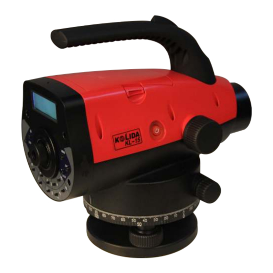
1. NAME OF EACH COMPONENT & ITS FUNCTION 1.1 Name of Each Component... - Page 8 battery rough collimator LCD display keyboard panel keys eyepieces: use for adjusting the definition of the crosshair. protecting cover of eyepieces: by releasing this cover, you can implement the mechanical adjustment of the reticle in order to correct the optical collimation line error.
-
Page 9: Operation Keys & Functions
1.2 Operation Keys & Functions name function Power ON/OFF Power ON/OFF, and start to measure. POW/MEAS measure Power ON: press once; Power OFF: hold on for 2 seconds. MENU menu Return to the menu list. DIST distance In measurement status, press it to start measure measure the distance and display the distance. -
Page 10: Preparation For Measurement
2. PREPARATION FOR MEASUREMENT 2.1 Mounting the Instrument Placing the Tripod. Type E aluminum tripod with flat or dome head tripod is required. (1) Adjust the three legs of the tripod to a proper length and tighten the fixing screws at the middle of the leg. (2) Tighten the hexagonal nut on the head of the tripod in order to make the tripod legs not too loosen. -
Page 11: Power On
the bubble and screw C is perpendicular to the line between screw A and B (refer to Picture A). Then rotate the screw C to move the bubble to the center of the central circle. This procedure should be repeated for times until the bubble is centered on any directions. -
Page 12: Setting The Data Save Mode
half battery low. Please change anther battery or charge the battery. unable to measure. The power will be cut off soon. You need to change the battery. 2.4 Setting the Data Save Mode In order to save the measurement data into the internal memory of the instrument, before leveling measurement, the data saving mode should be set to auto save, as the default setting is “OFF”. -
Page 13: Surveying Note
A precise focusing can shorten the measuring time and improve the accuracy. Measurement of high accuracy requests precise focusing as well as continuous measures. (2) Obstacles Measurement can be implemented if the staff is blocked less than 30%. Even if the crosshair center is blocked, as long as the field of view is blocked less than 30%, measurement still can be implemented. -
Page 14: Measure
3. MEASURE 3.1 Measure Mode This mode is to measure the staff reading and distance without calculating the height. Refer to “Set” to set the measure times. Using the average value upon several times can improve the accuracy. Operation Procedure Operation Display Menu... -
Page 15: Gh (Stake Out Ground Height)
3.2 S.O GH (Stake out Ground Height) Under this mode, user can stake out by inputting the ground heights (GH) of backsight point and stakeout point. Operation Procedure Operation Display Menu 1. Press [ENT] [ENT] ►1.Measure ↓ 2.Press [▲] [▼] to select “2.Stake out” [ENT] 1.Measure Mode ►2.Stake out... -
Page 16: Hd (Stake Out Height Difference)
3.3 S.O HD (Stake out Height Difference) User can stake out by inputting the HDs (height differences) of the backsight point and the stakeout point. Operation Procedure Operation Display Menu 1. Press [ENT]. [ENT] ►1.Measure ↓ 2.Press [▲] or [▼] to select “layout” [ENT] 1.Measure Mode ►2.Stake out... -
Page 17: Dist (Stake Out Distance)
3.4 S.O Dist (Stake out Distance) User can stake out by inputting the distance. Operation Procedure Operation Display 1. Press [ENT]. [ENT] Menu ►1.Measure ↓ 2.Press [▲] or [▼] to select “S.O Dist” [ENT] 1.Measure Mode (stake out distance) and press [ENT]. ►2.Stake out ↓... -
Page 18: Leveling
3.5 Leveling In Leveling mode, the saving mode should be set to “Auto” or “Manual save”. In this session we set it Auto Save. Operation Procedure Operation Display 1. Press [ENT]. [ENT] Menu ►1.Measure ↓ 2.Press [▲] or [▼] to select “Leveling” [▼] 1.Measure Mode and press [ENT]. - Page 19 Input point FS PN number 9.Input the point number of frontsight =>P2_ point and press [ENT]. [ENT] Meas the FS Pt 10. Collimate the staff until it is clear and press [MEAS]. [MEAS] FRod: 0.9550m FDist: 8.486m [►] or [◄] 11 ....
-
Page 20: Gh&Hd
Measurement value of front sight point FRod:1.032m FDist: 15.07m Ground height of front sight point G H: 22.555m Point number of front sight point Height distance of this station H D: 0.532m ∑: 25.003m Total length When the measurement of interval point is finished, press [▲] or [▼] to display the following screen. - Page 21 Save Data? 3. Press [ENT] to save the data. [ENT] Y: ENT N:ESC Input job Job Name? 4. Input the job name and press [ENT]. name =>H5_ [ENT] [ENT] 5.Input the GH (ground height) of the Input BS GH? backsight point. Y:ENT N:ESC Input point...
-
Page 22: Adjust
4. ADJUST Inspection of the collimating sight line (i angle) of the instrument. (1) As Picture 1 displays, mount the instrument on a tripod between 2 staff which is 50m away from each other. Divide the distance between A and B into 3 sessions with the same distance. - Page 23 Adjust 5.Press [ENT]. Ab Rod:1.023m [ENT] Relocate You can power off the instrument and A------------------ >B move it. Adjust [MEAS] 6. Press [MEAS]. a< ----B------b [ENT] 7.Press [ENT]. Adjust Ba Rod:0.808m [MEAS] 8. Press[MEAS]. Adjust a -----B------ >b Adjust 9. Press [ENT]. [ENT]...
-
Page 24: Parameter Setting
5. PARAMETER SETTING Meas.Mode N Times/Continuous Min.Reading 1mm/0.5mm Inverse Not Use/Use Meas Para. Mode Display Unit m(meter)/ft(US. ft) Save Mode OFF/Auto/Manual save Auto OFF On/Off Contrast Backlight Off/On Ins.Para. Ins.Info Date/SN# Regis.Info Setting the measuring times of average measurement. Operation Procedure Operation Display 1. -
Page 25: Data Manage
6. DATA MANAGE Operation Procedure Operation Display Menu 1. Press [▲] or [▼] to Data Manage. [▲]or[▼] ►1.Measure ↓ [ENT] ►4. Data Manage ↓ 2. Press [ENT]. [ENT] ►1.Input PN 3. Press [▲] or [▼] and [ENT] to select. [▲] or [▼] ↓... -
Page 26: Other Functions
7. OTHER FUNCTIONS 7.1 Distance Display [DIST] Use the [DIST] to measure the distance before surveying, to make sure the distances between the frontsight and backsight are same. 7.2 Inverse Staff Mode [-] Under this model, staff can be inverted for the ceiling measure. Firstly, set the “Inverse Mode”... -
Page 27: Battery And Charger
8. BATTERY AND CHARGER The on-board battery is B-21. Charging (1) The output voltage of the charger is AC110V~220V. The electric current is 450mA. (2) Red light means the battery is being charged. Green light means charging is finished. (3) It will take 5 hours to charge the battery. Note: a. - Page 28 (1) Notice the temperature when storing the instrument, especially the temperature inside the car in hot summer. (2) The battery should be removed if the instrument is going to be stored for a long time. (3) Do not store the wet instrument into the case before it is wiped dry. Clean (1) Clean the instrument after use.
-
Page 29: Specification
11. SPECIFICATION KL-15 height accuracy digital reading 1.5mm (standard deviation for 1km double run optic reading 2.0mm leveling) D≤10m:10mm;D>10m:D*0.001 distance accuracy digital reading distance range digital reading 1.5m~100m 1mm/0.5mm minimum display distance 0.1/1cm measuring time within 3s in normal condition magnification 32×...
Need help?
Do you have a question about the KL-15 and is the answer not in the manual?
Questions and answers
how to take level readings using the kolida kl 15 level