
Related Manuals for PowerWalker VFI 10K ICT IoT 3/3 BI


Summary of Contents for PowerWalker VFI 10K ICT IoT 3/3 BI
- Page 1 PowerWalker VFI 10k ICT/ ICR IoT VFI 20k ICT/ ICR IoT 3-Phase UPS Manual Uninterruptible Power Supply System Service and support: Call your local service representative...
- Page 2 SAFETY INSTRUCTIONS SAVE THESE INSTRUCTIONS. This manual contains important instructions that should be followed during installation and maintenance of the UPS and batteries. The UPS that are covered in this manual are intended for installation in an environment within O to SO°C, free of conductive contaminant.
- Page 3 Safety of persons RISK OF VOLTAGE BACKFEED. The system has its own power source (the battery). Isolate the UPS and check for hazardous voltage upstream and downstream during lockout- tagout operation. Terminal blocks may be energized even if the system is disconnected from the AC power source.
- Page 4 An additional AC contactor is used for back feed protection and must comply with IEC/EN 62040-1 (the creep age and clearance distances shall meet the basic insulation requirements for pollution degree 2). Disconnection and overcurrent protection devices shall be provided by others for ...
-
Page 5: Table Of Contents
CONTENTS 1 Introduction ........................1 1.1 Product features ......................1 1.2 Environmental protection ................... 2 2 Product Overview ......................3 2.1 Model list ........................3 2.2 Presentation ....................... 6 3 Installation ........................12 3.1 Unpacking and inspecting ..................12 3.2 Checking the accessory kit ..................13 3.3 Mechanical installation ..................... -
Page 6: Introduction
1 Introduction Thank you for selecting our UPS to protect your electrical equipment. We recommend that you take the time to read this manual to take full advantage of the many features of your UPS. Before installing your UPS, please read the booklet presenting the safety instructions. Then follow the indications in this manual. -
Page 7: Environmental Protection
1.2 Environmental protection Products are developed according to an eco-design approach. Substances This product does not contain CFCs, HCFCs or asbestos. Packing To improve waste treatment and facilitate recycling, separate the various packing components. The cardboard we use comprises over 50% of recycled cardboard. •... -
Page 8: Product Overview
Net Weights Unit Size Product Description (kg) (W x H x D) (mm) VFI 10K ICT IoT 3/3 BI VFI 15K ICT IoT 3/3 BI 146.7 VFI 20K ICT IoT 3/3 BI 159.5 300*805.5*633.2 VFI 15K ICT IoT 3/3 BX 52.9... - Page 9 Rack model: Net Weights Size Product Description (kg) (W x H x D)(mm) VFI 10K ICRS 16 TFT 23.8 RT 3-3 10KS 20 TFT RT 3-3 15KS 32 TFT RT 3-3 15KS 40 TFT 24.8 RT 3-3 20KS 32 TFT RT 3-3 20KS 40 TFT 438*129(3U)*559 RT 3-3 10K 16 TFT...
- Page 10 Optional modular or accessory: If order other type function modular or accessories, please contact distributors/agents. Type Description Remark RT 3-3 10K/15K/20K MBP For Rack model only Rack MBP For Rack model only in a parallel RT 3-3 10K/15K/20K PARA MBP system installation Dry Contact card (AS400) Intelligent...
-
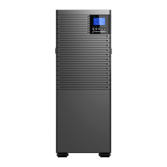
Page 11: Presentation
2.2 Presentation 2.2.1 Tower model: • UPS modular: Front view 1. Ventilation area 2. LCD Modular, including: (1)---Power button (2)---Touch screen (3)---LED indicator... - Page 12 Rear view 1. Intelligent slot 2. RS232 3. Ethernet port {RJ45, for IoT function) 4. USB 5. Wireless {HDMI, For IoT function) 6. Parallel port {optional by factory, default is no) 7. DRY in/out 8. RPO 9. RJ45 {for EBM detect) 10.
- Page 13 • EBM {External Battery Modular): Front view 1. Ventilation area 2. EBM label Rear view 1. Fuse board cover (replace EBM fuse) 2. EBM port 1 3. EBM port 2 4. EBM detection (RJ45 port)
- Page 14 2.2.2 RT model: UPS Modular • Front view 1. Ventilation area 2. LCD Modular, including: (1)---Power button (2)---Touch screen (3)---LED indicator Rear view 1. Intelligent slot 7. DRY in/out 2. RS232 8. RPO 3. Ethernet port {RJ45, for IoT function) 9.
- Page 15 EBM {External Battery Modular): • Front view 1. EBM label area 2. EBM label Rear view of EBM (for l0kVA) 1. Fuse board cover (replace EBM fuse) 2. EBM port 1 3. EBM port 2 4. EBM detection Box (RJ45 port) 5.
- Page 16 Rear view of EBM (for 15/20kVA) 1. Fuse board cover (replace EBM fuse) 2. EBM port 1 3. EBM port 2 4. EBM detection Box (RJ45 port) 5. Ground screw...
-
Page 17: Installation
3 Installation It is recommended to move the equipment to the installation site by using a pallet jack or a truck before unpacking. The system may be installed only by qualified electricians in accordance with applicable safety regulations. The cabinet is heavy, please install it with at least two peoples. 3.1 Unpacking and inspecting Unpacking the unit in a low-temperature environment may cause condensation occurred in and on the cabinet. -
Page 18: Checking The Accessory Kit
RT EBM Note: The cabinet is heavy, please see weight provided on the carton/label. Do not lift the unit’s front panel and rear panel. Discard or recycle the packaging in a responsible manner or store it for future use. Packing materials must be disposed in compliance with all local regulations concerning waste. -
Page 19: Mechanical Installation
√ √ USB cable RS232 cable Parallel cable √ √ Tower foot √ √ √ Rack ear Rack rail kit √ Quick start (EBM) √ √ User manual (UPS) √ Note --- Standard configuration; O---Option, default is Not configured : 3.3 Mechanical installation 3.3.1 Tower model To keep air-flowing freely, it is recommended to keep a clearance with 500mm space... - Page 20 EBM model It is recommended to place EBM modular to UPS’s right side. 1.Place the unit on a flat surface in its final location and install ‘Tower foot’ for stability. 2.Install the unit to ground(optional): place 4pcs bolts (M8 is recommended) to the final location previously, bolt’s position please refer to below, then fix the unit to the bolts.
- Page 21 Fasten the rail kit to the cabinet with 8pcs M5 screws + washers (as below): 2. Install ‘Rack ear’ to the unit by the M4 screws (flat head). 3. Slide the unit into ‘rail kit’ and make sure tighten the ‘rack mounting screw’.
- Page 22 EBM model EBM modular installation steps are same as UPS as above, Pay attention to this installation: 1. EBM modular must be installed on the lower level of the UPS {as shown below). 2. 2 EBMs are required for RT 15/20kVA UPS, each EBM with a height of 3U; therefore, 6U installation space is required.
-
Page 23: Power Cables Connection
3.4 Power cables connection This chapter introduces how to wire AC IN/OUT cable to UPS in different mode, and UPS connecting with EBM/MBP. 3.4.1 Input /Output wiring specification Before wring UPS, upstream breaker and backfeed contactor should be configured to avoid power backfeed to unity. - Page 24 Recommended circuit breaker and contactor current specifications: UPS power rating Input mode Breaker Contactor 1 phase main input ≥80A 3 phase main input ≥32A 10000VA 1 phase bypass input ≥63A 3 phase bypass input ≥32A 1 phase main input 125A ≥125A 3 phase main input ≥50A...
- Page 25 Recommended cable minimum cross-sectional area (unit: mm2) Input Output Battery Main input Bypass input Input/ power Output rating Mode 10000VA 15000VA 20000VA Note: 1. Please select the larger cross-section conductor for the UPS input cable in the single source application. 2.
- Page 26 Tower model: Remove the cover of terminal block, Layout of AC input/output as below: Note: 1. UPS input: PE/N/N/mL1/bL1/mL2/bL2/mL3/bL3{'m' is main input, 'b' is bypass input) 2. UPS output: N/N/L1/L2/L3/PE UPS provide busbars {as below) for 6 modes of wiring application, default is 3-3 mode {single source).
- Page 27 Mode 3-3(single source) Input: Connect ground cable (PE) to ground screw of chassis first; Short terminal N/N with busbar #1, connect AC cable(N); Short terminal mL1/ bL1 with busbar #1, connect AC cable(L1); Short terminal mL2/ bL2 with busbar #1, connect AC cable(L2); Short terminal mL3/ bL3 with busbar #1, connect AC cable(L3).
- Page 28 ode 3-1(single source) Input: Connect ground cable (PE) to ground screw of chassis first; Short terminal N/N with busbar #1, connect AC cable(N); Short input terminal mL1/bL1/bL2/bL3 with busbar #4, connect to AC cable(L1); Connect terminal mL2 to AC cable(L2) and terminal mL3 to AC cable(L3). Output: Connect ground cable (PE) to ground screw of chassis first;...
- Page 29 de 1-1(single source) Input: Connect ground cable (PE) to ground screw of chassis first; Short terminal N/N with busbar #1, connect AC cable(N); Short terminal mL1/bL1/mL2/bL2/mL3/bL3 with busbar #6, connect AC cable(L). Output: Connect ground cable (PE) to ground screw of chassis first; Short terminal N/N with busbar #1, connect AC cable(N);...
- Page 30 RT model: Remove the cover of terminal block, Layout of AC input/output as below: Note: 1. UPS input (PE/N/N/L1/L2/L3) 2. UPS bypass input(L1/L2/L3) 3. UPS output (PE/N/N/L1/L2/L3) 4. External battery port (PE/+/N/N/-) UPS provide busbars and jumper cables as below for 6 modes of wiring application, default is Mode 3-3(single source).
- Page 31 Mode 3-3(single source) Input: Connect ground cable (PE) to chassis first; Short terminal N/N with busbar #1, connect AC cable(N); Connect input terminal L1/L2/L3 with AC cable(L1/L2/L3) and jumper cable, then fix ‘jumper cable’ to bypass terminal L1/L2/L3’. Output: Connect ground cable (PE) to chassis first; Short terminal N/N with busbar #1, then connect AC cable(N);...
- Page 32 Mode 3-1(single source) Input: Connect ground cable (PE) to chassis first; Short terminal N/N with busbar #1, connect AC cable(N); Connect input terminal L2/L3 to AC cable(L2/L3); Fix ‘jumper cable’ to input terminal L1 and busbar #2, short bypass terminal L1/L2/L3 with this busbar #2, connect AC cable(L1).
- Page 33 Mode 1-1(single source) Input: Connect ground cable (PE) to chassis first; Short terminal N/N with busbar #1, connect AC cable(N); Fix ‘jumper cable’ to input terminal L1/L2/L3 and busbar #2, short bypass terminal L1/L2/L3 with this busbar #2 and connect AC cable(L). Output: Connect ground cable (PE) to chassis first;...
- Page 34 3.4.3 Wiring with external battery modular (EBM) (DC source to UPS) 1. Be sure to disconnect the battery cable from the EBM before connecting the battery terminals of the UPS. 2. Make sure the UPS is completely off before connecting or disconnecting the EBM. 3.
- Page 35 RT EBM For 10kVA UPS: Note: Extended runtime with up to 6 EBMs for each RT 10kVA UPS. For 15-20kVA UPS: Note: Extended runtime with up to 6 sets of EBM for each RT 15/20kVA UPS.
- Page 36 Connect with user’s own EBM: Tower model: Connect user’s own EBM to UPS with ‘Battery cable’(if configured). RT model: Connect user’s own EBM to UPS with below indication of ‘External battery port’: Note: 1. The EBM must be grounded individually or grounded to UPS. 2.
- Page 37 3.4.4 Wiring with RT MBP (MBP source to RT UPS only) RT MBP is RT UPS’s optional modular, UPS can be used with the MBP to implement the maintenance bypass switching function to ensure that the output of the system is not affected during the UPS maintenance.
-
Page 38: Parallel System Installation And Operation (Optional)
4.1 Wiring for AC/DC cable 1. Wiring length requirement: When the distance between the load and the parallel UPS is less than 10 meters, the length difference between the input/output lines between the UPSs in the parallel system is less than 20%. When the distance between the load and the parallel UPS is greater than 20 meters, the length difference between the input/output lines between the UPSs in the parallel system is less than 5%. - Page 39 Parallel system installed by 15kVA UPS (conductor cross-section, unit: mm2) Main input Bypass input Output Mode number 2 UPS 3 UPS Parallel system installed by 20kVA UPS (conductor cross-section, unit: mm2) Main input Bypass input Output Mode number 2 UPS 3 UPS Note: 1.
- Page 40 4.1.2 Wiring for AC cable (AC source to UPS) AC cable wiring are shown in below diagrams for different configuration. 3-3 configuration (single source) 3-3 configuration (dual source) ...
- Page 41 3-1 configuration (single source) 3-1 configuration (dual source) ...
- Page 42 1-1 configuration (single source) 1-1 configuration (dual source) ...
-
Page 43: Wiring For Parallel Signal Cable
4.1.3 Wiring with external battery modular (EBM) (DC source to UPS) Parallel UPS connection with ‘independent battery’ In the parallel system, independent EBM connect to each UPS please refer to chapter 3.4.3. Parallel UPS connection with ‘common battery’ In the parallel system, you can also set up ‘common battery’(user’s own battery) for all UPSs. -
Page 44: Parallel System Operation
Connect each UPS one by one with ‘parallel cable’, make sure the cable is screwed to parallel port tightly. It is recommended to lock the ‘parallel cable’ (as above) for preventing the parallel ports suffering an unexpected pulling-force and causing the parallel system fault. 4.3 Parallel system operation 1. -
Page 45: Operation
5 Operation 5.1 LCD panel The UPS has a touch graphical LCD. It provides useful information about the UPS itself, load status, events, measurements, and settings. The LED: LED status description UPS status Red on Fault mode Red flash General alarm Yellow on Battery mode Yellow flash... -
Page 46: Lcd Description
5.2 LCD description Display Area Icon Description Battery status Battery capacity Backup time UPS mode The work mode of the UPS Load percentage When it is 3 phase output, the load for each of the 3 phases is displayed in this area Bypass status and Different icon shows the phase... -
Page 47: Menu Structure
Energy flow chart The sick solid line means there is energy flow, the double thin line means nothing System time It can be set in user settings Menu icon Click on this icon can entry the menu screen Alarm area When UPS enters fault mode, fault ICON and the fault information will be displayed. -
Page 48: Control And Product Information
5.4 Control and product information Main menu Submenu Menu function Battery test Starts a manual battery test in stand-alone mode Reset IoT function Reset IoT function inside UPS Battery test (Parallel) Starts a single battery test in parallel mode Control Reset fault Clear active fault Reset factory setting... -
Page 49: Starting The Ups With Utility
[Normal mode], [ECO mode], UPS Mode Normal mode [CVCF mode] Output voltage [220V], [230V], [240V] 230V Output frequency [Auto detection], [50Hz], [60Hz] Auto detection Output ESS function [Enabled], [Disabled] Disabled Auto bypass [Enabled], [Disabled] Enabled Auto restart [Enabled], [Disabled] Enabled Short circuit auto clear [Enabled], [Disabled] Disabled... - Page 50 Verify that the total UPS output load does not exceed the rated capacity of the • UPS. • The wiring of the UPS input and output is correctly connected according to the required mode. • Confirm that the UPS output device is not started. •...
-
Page 51: Starting The Ups On Battery
4. Power off the UPS again, insert the RPO terminal. 5.7 Starting the UPS on battery Before using this feature, the UPS must have been powered by utility power with output enabled at least once. Battery start can be disabled. See the "DC start" setting in "Battery/DC Start". To start the UPS on battery: Press the button for more than 0.1 seconds. -
Page 52: Communication
6 Communication 6.1 RS232 and USB 1. Communication cable to the serial or USB port on the computer. 2. Connect the other end of the communication cable to the RS232 or USB communication port on the UPS. 6.2 UPS remote control functions Remote Power Off (RPO •... -
Page 53: Iot
6.3 loT Built-in ethernet port and WLAN (optional accessary) port enable market-leading and easy-to-use IoT solutions for: Winpower View mobile app which allows you to remote monitor UPS(s) and keep informed about critical UPS event always. Remote report UPS faults and status (contact with your service for detail) from APP or registered APP account (Email address). -
Page 54: Modbus Tcp
For more detail information and Q&A about the IoT and APP, please refer to the HELP menu in the app. - Wireless network connection The wireless module (WLAN dongle} is optional, please contact your local distributor for details. 6.4 Modbus TCP Built-in ethernet port offers Modbus TCP feature to facilitate remote monitoring of the UPS into your own software. - Page 55 Installation procedure: 1. Go to the website: https://powerwalker.com/?lang=en&page=winpower 2. Choose the operation system you need and follow the instruction described on the website to download the software. 3. When downloading all required files from the internet, enter the serial No: 511C1- 01220-0100-478DF2A to install the software.
-
Page 56: Ups Maintenance
7 UPS Maintenance 7.1 Equipment care For the best preventive maintenance, keep the area around the equipment clean and dust free. If the atmosphere is very dusty, clean the outside of the system with a vacuum cleaner. For full battery life, keep the equipment at an ambient temperature of 25°C {77°F). The batteries are rated for a 3-5 years service life. -
Page 57: Troubleshooting
8 Troubleshooting The UPS is designed for durable, automatic operation and also alert you whenever potential operating problems may occur. Usually the alarms shown by the control panel do not mean that the output power is affected. Instead, they are preventive alarms intended to alert the user. - Page 58 Click on “Event” icon Last 100 events If alarm exists, shows here. 4 messages for high priority alarm Problem Displayed Possible cause Remedy Phase and neutral conductor Site wring fault Reverse mains power wiring at input of UPS system are reversed Neutral wire missed Neutral abnormal...
- Page 59 UPS internal fault, the + DC Pos Bus Over Volt Consult dealer BUS voltage is too high UPS internal fault, the -DC Neg Bus Over Volt Consult dealer BUS voltage is too high UPS internal fault, the + DC Pos Bus Under Volt Consult dealer BUS voltage is too low UPS internal fault, the -DC...
-
Page 60: Specifications
9 Specifications 9.1 UPS block diagram 9.2 UPS specification Models 10KS 15KS 20KS 10kVA/ 10kVA/ 15kVA/ 15kVA/ 20kVA/ 20kVA/ Rated power 10kW 10kW 15kW 15kW 20kW 20kW Rated frequency 50/60Hz Voltage range (Phase voltage) 100~300VAC Rated voltage 220/230/240VAC Input (Phase voltage) Main input Rated current (3 Phase) - Page 61 Models 10KS 15KS 20KS Bypass input Rated current (1 Phase) Main input frequency for 3-3 40-70Hz Input and 3-1 mode Main input 60% rated load: 40-70Hz ≤ frequency for 60% rated load : 45-55Hz(50Hz system) / 54-66Hz(60Hz system) 1-1 mode >...
- Page 62 Models 10KS 15KS 20KS Criterion Safety IEC/EN 62040-1 IEC/EN 62040-2 Performance IEC/EN 62040-3 In CVCF mode or dual source input mode, UPS needs to be de-rated to 60% capacity for 1-1 mode (rated output power and maximum charging current). @ 220VAC input phase voltage, rated output power and maximum charging.
Need help?
Do you have a question about the VFI 10K ICT IoT 3/3 BI and is the answer not in the manual?
Questions and answers