Table of Contents
Advertisement
Quick Links
USER'S MANUAL
PowerWalker VFI 1000 / 3000VA
Uninterruptible Power Supply
CONTENTS
1. INTRODUCTION ...........................................................
2. SAFTY INSTRUCTION...............................................
3. SYSTEM DESCRIPTION..............................................
4. CABLE CONNECTION .................................................
5. OPERATION .................................................................
6. TROUBLE SHOOTING GUIDE.....................................
7. OPERATION MODES OF THE UPS ............................
8. COMPUTER INTERFACE ............................................
9. SPECIFICATIONS.......................................................
1
1
2
4
7
8
13
17
19
21
Advertisement
Table of Contents

Subscribe to Our Youtube Channel
Related Manuals for PowerWalker VFI 1000


Summary of Contents for PowerWalker VFI 1000
-
Page 1: Table Of Contents
CONTENTS USER’S MANUAL 1. INTRODUCTION ..........……..PowerWalker VFI 1000 / 3000VA 2. SAFTY INSTRUCTION....……...……………..3. SYSTEM DESCRIPTION......……..…..4. CABLE CONNECTION ......……..…... 5. OPERATION ..........……... 6. TROUBLE SHOOTING GUIDE.......……..… 7. OPERATION MODES OF THE UPS ....……..8. COMPUTER INTERFACE ......……... 9. SPECIFICATIONS.........…………..….. -
Page 2: Introduction
1. INTRODUCTION 2. SAFTY INSTRUCTION 1.1 General Description 2.1 Transporting The continuity of electrical power is an essential requirement for critical load 1. Disconnect all power cables if necessary. operations. The Uninterruptible Power System (UPS) is designed to meet the 2. -
Page 3: System Description
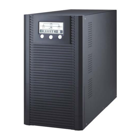
3. SYSTEM DESCRIPTION 2.4 Operation 1. Do not disconnect the mains cable on the UPS system or the building wiring 3.1 LCD Display(Includes detachable LCD function with connecting from socket outlet during operations since this would cancel the protective remote control port to RS-232) earthing of the UPS system and of all connected loads. - Page 4 5. Fault LED (red): To indicate the UPS is in fault condition because of inverter shutdown or over-temperature. 5~9. Load & Battery Capacity LEDs: 6. Warning LED (yellow): To indicate the UPS is in the status of overload, (a) No. 5 to 8 LED is green color and No. 9 (used as warning LED for bypass and battery back-up.
- Page 5 (buzzer beeps), press this key and the On/Test/Mute key at the same 2KVA / 3KVA Tower Case time to disable the buzzer. (c) When UPS is in operation this key is pressed with the Off key simultaneously for 3 seconds, the UPS will be switched off after two beeps 13.
- Page 6 2KVA / 3KVA Tower Case 3.4 Back View Description 1KVA Tower Case 1. DB 9 (RS-232) Interface Port 7. External Battery Socket 2. SNMP Intelligent Slot (Option) 8. Fan 1. DB 9 (RS-232) Interface Port 6. Fan 3. Fax / Modem (Surge Protection) 9 Breaker 2.
-
Page 7: Cable Connection
4. CABLE CONNECTION 5. OPERATION 5.1 Check Prior to Start Up 4.1 Inspection 1. Ensure the UPS is in a suitable positioning. 1. The system may be installed and wired only by qualified electricians in 2. Check input cord is secured. accordance with applicable safety regulations. - Page 8 5.4 LCD Display 5. Battery Status Menu Use Up/Down key to select menu-displays of the LCD described below. This screen will refresh once the system power is enabled. 1. Rated Spec Menu 2. Status Menu 6. Output Power Menu 7. Temperature Menu 3.
- Page 9 10. Output Voltage Set Menu 9. Bypass Range Set Menu A. In this screen, press on/off A. To protect the load, the function Control Key to enter the following of bypass auto-transfer is steps for output voltage setting. activated only when the AC main voltage is within the range of LO (low) and HI(high).
-
Page 10: Trouble Shooting Guide
3. LED and LCD status as below: 6. TROUBLE SHOOTING GUIDE 6.1 UPS Status and Action The description of the following guideline may be helpful in problem solving. 1. LED and LCD status as below: UPS STATUS: AC utility power is normal but UPS is overloaded. Warning LED lits up and buzzer beeps per second. - Page 11 5. LED and LCD status as below: 7. LED and LCD status as below: UPS STATUS: UPS STATUS: AC utility fails. The load is supplied by UPS in backup mode, and AC utility power is normal, but the load is supplied by AC utility power battery power is approaching low level.
-
Page 12: Operation Modes Of The Ups
7.3 AC Utility Failure 7. OPERATION MODES OF THE UPS The AC output comes from battery, passing through DC/AC inverter and 7.1 UPS System Block Diagram static switch within the battery backup time. 7.2 Normal Operation 7.4 Bypass Enable There are two main loops when AC utility is normal: the AC loop and the Under the following conditions, the bypass will be enabled: battery charging loop. -
Page 13: Computer Interface
8.2 DB9 Interface Connector 8. COMPUTER INTERFACE 8.1 communication interface The communication interface (DB9 port) on the back of the UPS may be connected to a host computer. The port provides communicating with the computer like below. Supply RS-232 for monitoring software of UPSilon 2000 DB9 INTERFACE CONNECTOR The UPS communicates with the computer by sending out RS-232 data DB9 PIN Assignment... -
Page 14: Specifications
9. SPECIFICATIONS Rated Power Capacity 1KVA / 700W 2KVA / 1400W 3KVA / 2100W Single phase 220Vac, 160~300Vac at 70~100% load Voltage 140~300Vac at 50~70% load, 118~300Vac at 0~50% load Input Frequency 50Hz or 60Hz +/- 4Hz ≧ 0.95 Power Factor Single phase 220Vac +/- 2% (230V or 240V re-settable via Voltage, Frequency LCD panel), 50Hz or 60Hz...
Need help?
Do you have a question about the VFI 1000 and is the answer not in the manual?
Questions and answers