Table of Contents
Advertisement
Quick Links
Advertisement
Table of Contents

Subscribe to Our Youtube Channel
Related Manuals for Neutronics QUICK DETECT


Summary of Contents for Neutronics QUICK DETECT
- Page 1 QUICK DETECT™ A/C SEALANT DETECTION KIT OPERATION MANUAL Manual Part Number: 5-06-7000-62-0 Manual File MN-A-0001 Rev. E Flow 456 Creamery Way, Exton, PA 19341 Phone: 610.524.8800 • Fax: 610.524.8807 • Email: info@neutronicsinc.com www.neutronicsinc.com...
-
Page 3: Table Of Contents
SSEMBLY ............................1-1 YRINGE SSEMBLY & S ........................1-1 ENSING AFETY ............................1-2 DDITIONAL TEMS ASSEMBLING THE QUICK DETECT ....................2-3 ..............................2-3 IRST 1 – P ......................2-3 REPARING THE ENSING 2 – I ......................2-3 NSERTING THE ENSING 3 –... - Page 4 APPENDICES ............................4-7 A - S ........................4-7 PPENDIX PARE ARTS B - S ........................4-7 PPENDIX PECIFICATIONS C - T ........................4-7 PPENDIX ROUBLESHOOTING 4.3.1 Low Flow Readings ........................4-7 4.3.2 No High Side Service Port ......................4-7 D – I ......................... 4-7 PPENDIX NTENDED APPENDIX E - W...
-
Page 5: For Your Safety
USE ONLY REPLACEMENT PARTS SUPPLIED BY NEUTRONICS INC. Use of non-authorized replacement parts will void all warranties and may result in false or erroneous test results. DO NOT UTILIZE QUICK DETECT SYSTEM WITHOUT SAFETY SHIELD. Use of system without safety shield may result in accidental release of refrigerant charges. -
Page 6: Welcome
Copyright ©2004 Neutronics Inc. This work is protected under Title 17 of the US Code and is the sole property of Neutronics Inc. No part of this document may be copied or otherwise reproduced, or stored in any electronic information retrieval system, except as specifically permitted under US copyright law, without the prior written consent of Neutronics Inc. -
Page 7: Component Identification
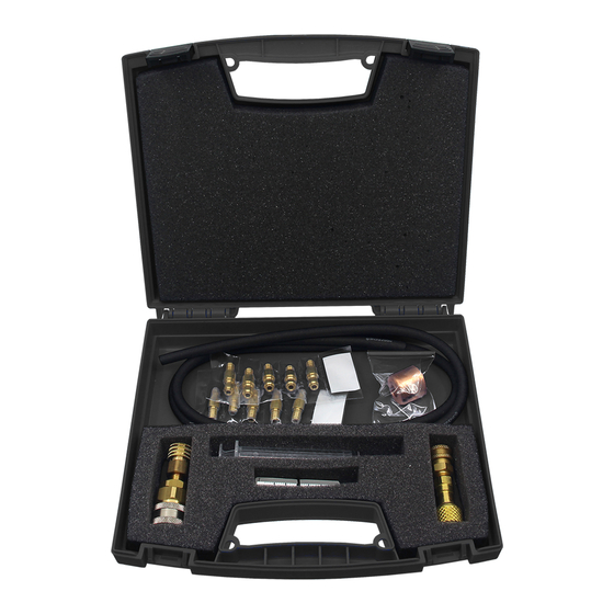
Component Identification OMPONENT DENTIFICATION Test Rig Provides connection of sensing plug to the high de or liquid service port of R134a or R12 based A/C systems. R134a Test Rig R12 Test Rig Flow Meter Assembly Provides visu al indication of refrigerant leak flow rate. Syringe Assembly Provides method for injection of water into sensing plugs ends... -
Page 8: Additional Items
Additional Items In addition t o the item described in 1.1 – 1.4, the kit also includes a length of rubber tu bing, a hook for hanging t he flow meter, a carrying/storage case and an instruction manual. Manual Part Number: Manual File: Revision Date: June 5, 2006 Page 1-2... -
Page 9: Assembling The Quick Detect
ETECT First Use Prior to first use, identify each of the Quick Detect omponents as described in 1.1 – 1.6, locate the High Side (liquid) service port on the vehicle, and select the pr oper coupler for an R12 or R134a vehicle. -
Page 10: Step 4 - Attaching The Hose
Figure 3 Figure 4 Step 4 – Attaching the Hose Attach one end of the hose to the Sensing Plug. (See Figure 4) Make sure the hose is completely seated over all of the ribs on the end of the plug. Step 5 –... -
Page 11: Testing For Sealant
Testing For Sealant ESTING FOR EALANT Preparing the Vehicle Step 1: Start vehicle engine and s et A/C system to the follow settings: Maximum cool Lowest temperature setting Highest fan speed Step 2: Allow the vehicle A/C system to operate for a minimum of 2- minutes to ensure full circulation and mixing of refrigerant charge. -
Page 12: Monitoring The Test
Warranty Monitoring the Test Observe flow meter reading for 3 minutes. Note that during the initial 30-60 seconds the flow rate may rise due to water being pushed through the sensing plug. Note the highest reading obt ained during the initial 60-seconds and compare to the reading obtained at the end of 3-minutes. At the end of the 3-minute period, disconnect the test rig from the A/C system high side port. - Page 13 Appendix A - Spare Parts List PART NUMB DESCRIPTION Quick Detect Kit 7-08-1000-51-0 Quick Detect Spare Sensing Plugs (25) 7-08-1000-52-0 Quick Detect Spare Parts Kit Items 1.2 thru 1.5 7-08-1000-53-0 endix B - Specificatio REFRIGERANT TYPES: R12, R134a PRESSURE: 250 PSIG Max.
- Page 14 Buyer, therefore, agrees to indemnify NEUTRONICS from and against all losses and claims to or by any person or property caused in any manner by the goods or the use of the goods, including any expenses and attorney’s fees in connection with all claims, demands, proceedings, or other expenses.
Need help?
Do you have a question about the QUICK DETECT and is the answer not in the manual?
Questions and answers