Table of Contents
Advertisement
Quick Links
Process Instruments
Engineered Solutions for Gas Detection and
Analysis
MODEL Mini-ICS
OXYGEN ANALYZER / CONTROLLER – PERCENT RANGE
Manual Part Number: 5-06-4900-53-0
Document Control Number: MN-A-0031
Revision Level: B – ECO 7822
Revision Date:
Phone: 610.524.8800 • Fax: 610.524.8807 • Email: info@neutronicsinc.com
OPERATIONS MANUAL
Neutronics
!
Reference Manual for
Installation and
Operation Instructions
April 14, 2006
A DIVISION OF
456 Creamery Way, Exton, PA 19341
www.neutronicsinc.com
MODEL Mini-ICS O
P
O
ERCENT
XYGEN
20.9
NORMAL
FAULT
LOW FLOW
Controller
2
O
ALARM
2
MODE
Advertisement
Table of Contents
Troubleshooting

Related Manuals for Neutronics NTRON Mini-ICS


Summary of Contents for Neutronics NTRON Mini-ICS
- Page 1 Process Instruments Engineered Solutions for Gas Detection and Analysis MODEL Mini-ICS OXYGEN ANALYZER / CONTROLLER – PERCENT RANGE OPERATIONS MANUAL Neutronics MODEL Mini-ICS O Controller ERCENT XYGEN 20.9 NORMAL FAULT LOW FLOW ALARM Reference Manual for Installation and MODE Operation Instructions...
-
Page 3: Table Of Contents
Table of Contents TABLE OF CONTENTS ............III FOR YOUR SAFETY: ............VII WELCOME ..............VIII CHAPTER 1 – INTRODUCTION AND OVERVIEW ......1-1 ............1-1 ENERAL ............1-2 EATURES ..........1-3 YSTEM ARDWARE VERVIEW 1.3.1 Main Board ............ 1-3 1.3.2 Relay Board ........... - Page 4 2.1.3.2 Flow Switch Status Input ........2-8 2.1.3.3 Oxygen Alarm Relay Outputs ........ 2-8 2.1.3.4 Inert Gas Control Relay Outputs ......2-9 2.1.3.5 Fault Relay Outputs ........2-9 2.1.3.6 Remote Calibration Relay Outputs ......2-9 2.1.3.7 Analog Voltage Output ........2-10 2.1.3.8 Analog Current Output ........
- Page 5 4.1.1.7 User Setup 7: Serial Output Format......4-2 4.1.1.8 User Setup 8: Sensor Disconnect Detection Test.... 4-3 4.1.1.9 User Setup 9: Minimum Analog Output Voltage Concentration . 4-3 4.1.1.10 User Setup 10: Maximum Analog Output Voltage Concentration4-3 4.1.1.11 User Setup 11: Minimum Analog Output Current Concentration4-3 4.1.1.12 User Setup 12: Analog Current Full Scale.
- Page 6 4.3.1.15 Fault Code 28 – Calibration Mode active ....4-25 4.3.1.16 Fault Code 29 – Manual Relay Control active ..... 4-25 4.3.1.17 Fault Code 30 – User Setup Mode active ....4-26 .1.18 Fault Code 31 – Factory Setup Mode active ....4-26 .1.19 Fault Code 32 –...
-
Page 7: For Your Safety
For Your Safety: PLEASE READ THIS MANUAL IN ITS ENTIRETY BEFORE ATTEMPTING INSTALLATION OR OPERATION! Attempting to operate the Model 1100 without fully understanding its features and functions may result in unsafe conditions • Always use protective eye wear and observe proper safety procedures when working with pressurized gases. -
Page 8: Welcome
This work is protected under Title 17 of the US Code and is the sole property of Neutronics Inc. No part of this document may be copied or otherwise reproduced, or stored in any electronic information retrieval system, except as specifically permitted under US copyright law, without the prior written consent of Neutronics Inc. -
Page 9: Chapter 1 - Introduction And Overview
NTRODUCTION AND VERVIEW 1.1 General The Model Mini-ICS [Inert Gas Control System] analyzer by Neutronics offers a cost effective solution in a small package for industrial process Oxygen measurement and inert gas control applications for flash- fire/explosion prevention, or product quality. -
Page 10: Features
1.2 Features The Model Mini-ICS analyzer module is designed to be flush mounted to a panel or console. Packaging options available from Neutronics Inc. include General Purpose and Explosion Proof surface-mount enclosures, and custom rack-mount designs. Because of the small size of the Model Mini-ICS analyzer, the basic panel-mount unit can be integrated into a variety of equipment or control panels. -
Page 11: System Hardware Overview
System Hardware Overview 1.3 System Hardware Overview Control Panel Power Supply Board Relay Board Chassis Main Board Display Board Figure 3 – basic analyzer 1.3.1 Main Board The main board houses the microprocessor, and supporting electronics for controlling the operation of the Model Mini-ICS Analyzer. The main board receives the sensor signal and flow switch inputs, and provides the control and display functions of the analyzer. -
Page 12: Control Panel
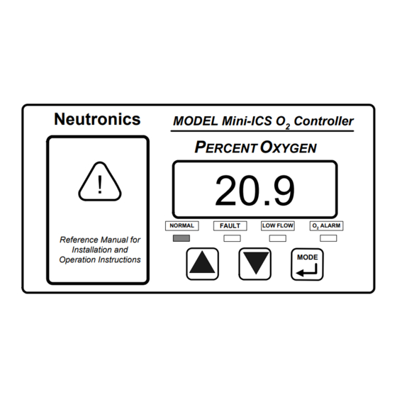
System Installation and Startup 1.3.5 Control Panel The Control Panel serves as the main user interface. The Control Panel features the keypad (ramp-UP, ramp-DOWN, and MODE keys) and the status LED’s. The control panel is designed to be splash and water-resistant. At the four corners of the panel are the #8-32 mounting studs, which allow flush mounting of the instrument to a control or equipment panel. - Page 13 System Hardware Overview 4-20 mA Output RS 232 COM Line Analog Voltage Output Range ID Output Fault and Remote Calibration Relay Outputs Alarm & Inert Gas Control Relay Outputs Relay Board Sensor Line Power Main Board Filter Supply Flow Switch Display Mains Power Board...
-
Page 14: System Inputs And Outputs
The Flow Switch Status electrical interface is used to indicate the flow status sample from process Oxygen Sensor, extractive applications where a Neutronics Inc. Sampling System has been provided. A closed flow switch indicates sufficient sample flow. open Flow Switch indicates... -
Page 15: Fault Relay Output
System Hardware Overview The purpose of the ICS relay is to control the flow of inert gas to the process being monitored, to keep Oxygen levels in the process within an acceptable range at all times. Purging the process with inert gas lowers the Oxygen concentration in the process. -
Page 16: Range Id Output
System Installation and Startup 1.4.9 Range ID Output To remotely detect the present range of Oxygen concentration, the Model Mini-ICS features a 0-10 volt Auto-Range Identification output. Range ID output is used in conjunction with the Analog Voltage and Analog Current outputs when... -
Page 17: Front Panel User Interface
1.5 Front Panel User Interface 1.5.1 The “UP” Pushbutton The “UP” pushbutton can be used to program the Mini-ICS Analyzer via the front panel. This momentary push-button soft key is used to enter incremental information. Its function is menu-driven. 1.5.2 The “DOWN” Pushbutton The “DOWN”... -
Page 18: Fault Indicator Led
System Installation and Startup 1.5.8 Fault Indicator LED The purpose if the Fault Indicator LED is to inform the user via the front panel that at least one system fault, other than the Low Flow Fault is active. Note that when the Fault Indicator LED is active, the Fault relay will... -
Page 19: Chapter 2 - System Installation And Start-Up
Installing the Analyzer 2 – S HAPTER YSTEM NSTALLATION TART 2.1 Installing the Analyzer STEP 1: LOCATE THE ANALYZER... PANEL CUTOUT STEP 2: INSTALL THE SENSOR… Sam pling Package STEP 3: INSTALL TH E AN ALYZER Figure 6 – installation outline Manual Part Number: Revision Level: B Revision Date:... -
Page 20: Step 1 - Locate And Mount The Analyzer Unit
System Installation and Startup 2.1.1 Step 1 – Locate and Mount the Analyzer unit The Model Mini-ICS is designed to be mounted flush to the surface of equipment or on a control panel. Select a suitable location for the Model Mini-ICS analyzer unit where the digital display and status LED’s will be easy to read, and the interface buttons on the display panel will be easy to access. -
Page 21: Step 2 - Install The Oxygen Sensor
Neutronics-specified Sampling system. For sensor installation and pneumatic connections for the Neutronics Inc. Sampling system, please refer to the Sampling System Manual. 2.1.3 Step 3 – Install the Analyzer DANGER: Electrical connections on the rear of the Model Mini- ICS Oxygen analyzer may have hazardous voltages present once power has been applied to the unit. - Page 22 System Installation and Startup TRON Mini-ICS Analyzer PROCESS ANALYZER DIVISION AC POWER INPUT AC-N AC-L 90-264 VAC, 47-63 Hz, 20 VA RANGE VALVE FAULT ALARM VALVE V-OUT BAT. BU V-OUT I-OUT RS-232 NO CONNECTION 12V DC ANALOG SERVICE PORT Figure 8 – analyzer electrical interface...
- Page 23 Installing the Analyzer Power In Sensor/ Flow Switch In Alarms/ Range ID Out Serial/ Analog Out 11- 30 VDC INPUT, 2.5W VDC+ 90- 264 VAC INPUT, 2.5VA AC- L AC- N Range Fault O2 ALARM ICS VALVE V- Out VALVE NC NO NC NO Bat.
-
Page 24: Oxygen Sensor Input
System Installation and Startup 2.1.3.1 Oxygen Sensor Input Connections to the sensor are made at terminal block TB4 on the rear of the analyzer chassis. Be certain to match the terminal pins against the terminal ID label on the top of the analyzer chassis. Refer to Appendix F –... -
Page 25: Inert Gas Control Relay Outputs
Installing the Analyzer 2.1.3.4 Inert Gas Control Relay Outputs Connections from the Inert Gas Control relay contacts to a Neutronics Inc. Inert Gas Control solenoid valve are made at terminal block TB2 on the rear of the analyzer chassis, for stand-alone control of Oxygen in a process vessel or stream. -
Page 26: Analog Voltage Output
System Installation and Startup 2.1.3.7 Analog Voltage Output Connections from Analog Voltage output user’s auxiliary equipment are made at terminal block TB3 on the rear of the analyzer chassis. Be certain to match the terminal pins against the terminal ID label on the top of the analyzer chassis. -
Page 27: Rs-232 Service Port
Installing the Analyzer Range V-Out Valve Fault O2 Alarm ICS Valve NC NO C NO C NO NC NO 2.1.3.10 RS-232 Service Port Connections from the Range ID output to the user’s auxiliary equipment are made at terminal block TB3 on the rear of the analyzer chassis. certain to match the terminal pins against the terminal ID label on the top of the analyzer chassis. -
Page 28: Mains Power
System Installation and Startup 2.1.3.12 Mains Power Connections for Mains Power input are made at terminal block TB1 on the rear of the analyzer chassis. Be certain to match the terminal pins against the terminal ID label on the top of the analyzer chassis. For VAC versions, use minimum16-AWG, 3-conductor, stranded-wire, for the connections. -
Page 29: Starting Up And Commissioning The System
Starting up and Commissioning the System 2.2 Starting up and Commissioning the System STEP 1: POWER UP STEP 2: INITIAL CALIBRATION STEP 3: SET OXYGEN ALARM & INERT GAS CONTROL LIMITS Figure 10 – start-up The Model Mini-ICS is shipped ready to use, right from the carton. Factory default configuration settings are listed in Appendix C for your information. - Page 30 System Installation and Startup Following self-test, the analyzer will enter into one of its RUN modes (section 3.3). The analyzer will check its input reading and update the 7-segment alphanumeric display and status LED’s accordingly. Though the unit can be immediately used after self-test, best stabilization of the sensor signal may be obtained after the instrument has been on for approximately 20 minutes.
-
Page 31: Step 2 - Calibrate The Unit
Neutronics Inc. offers commissioning, and Factory Acceptance Testing services by our qualified technicians. You may contact the Neutronics factory toll-free at (800) 524-8800 (continental United States only. Elsewhere, (610) 524- 8800) and ask an Ntron Division Service Technician to schedule service two (2) weeks in advance. -
Page 33: Chapter 3 - Analyzer Operation
RUN Modes 3 – A HAPTER NALYZER PERATION 3.1 System Organization The Model Mini-ICS has two types of operational modes – User-type, and Run-type. “User” modes are initiated and controlled by the user, and are used to setup and m aintain the analyzer. -
Page 34: Procedure For Calibrating The Model Mini-Ics
30-seconds at the beginning of its Calibration routine (user configurable – section 4.1.2). If you are using a Neutronics Process Sampling System, or Process Sample Conditioning Package, follow the instructions in the equipment manual applying calibration apparatus. -
Page 35: Set Oalarm
RUN Modes 3.2.2 SET O ALARM Mode To enter Set O Alarm mode from any Run mode using the keypad; scroll through the User Mode menu by pressing momentarily the “MODE” button two (2) times, until the 7-segment alphanumeric display reads “AL” (Set O Level). - Page 36 System Installation and Startup Neutronics MODEL Mini-ICS O Controller ERCENT XYGEN FAULT LOW FLOW ALARM Reference Manual for Installation and MODE Operation Instructions...
-
Page 37: Run Modes
RUN Modes 3.3 RUN Modes After power-up and self-test, and analyzer immediately enters into one of its Run modes – Normal, O Alarm Active, Inerting Control Active, or Fault Active. The Run mode active at any time, provided no manual input is received at the front panel or service port, is determined by the analyzer setup parameters entered at the factory, and by the user, compared against the analyzer’s monitored inputs and other monitored... -
Page 38: Inerting Control Active Mode
System Installation and Startup 3.3.3 INERTING CONTROL ACTIVE Mode The Model Mini-ICS initiates Inerting Control Active mode when it has detected that measured Oxygen concentration exceed threshold value of the High Inerting Control Limit (section 3.2.3). will also become active when system Fault... -
Page 39: Fault Active Mode
RUN Modes The 7-segment alphanumeric display will flash and continue to display the measured Oxygen level. The “NORMAL” indicator LED will remain lit. The Inerting Control relays will change state according to the analyzer configuration. Inerting Control function will cleared automatically when measured Oxygen concentration falls below the set threshold value of the Low Inerting Control Limit. -
Page 41: Chapter 4 - Maintenance And Troubleshooting
Neutronics Ntron division Service Department for assistance. 4.1.1 System Setup via Front Panel Keypad The Front Panel User Setup menu may be accessed from the Mini-ICS front panel by pressing and holding the “MODE”... -
Page 42: User Setup 1: Ics And O2 Alarm Relays Failsafe/Non Failsafe.4-2
Maintenance and Troubleshooting 4.1.1.1 User Setup 1: ICS and O2 Alarm Relays Failsafe/Non Failsafe. This parameter allows the user to set the ICS and O Alarm relays to either failsafe or non-failsafe. Failsafe is defined as; the relay active mode is similar to when the Model Mini-ICS is not powered. Non- Failsafe mode is defined as;... -
Page 43: User Setup 8: Sensor Disconnect Detection Test
System Setup 4.1.1.8 User Setup 8: Sensor Disconnect Detection Test. This parameter allows user enable disable sensor disconnect testing. Sensor disconnect is used to determine whether or not there the sensor is connected to the Model Mini-ICS analyzer. Valid Settings: 0 (Disable Sensor Disconnect Detect), 1 (Enable Sensor Disconnect Detect). -
Page 44: Not Active For This
Maintenance and Troubleshooting 4.1.1.13 User Setup Current Year. ACTIVE THIS RELEASE** 4.1.1.14 User Setup 14: Set Current Month. ** NOT ACTIVE FOR THIS RELEASE** 4.1.1.15 User Setup Current Day. ACTIVE THIS RELEASE** 4.1.1.16 User Setup Current Hour. ACTIVE THIS RELEASE** 4.1.1.17 User Setup 17: Set Current Minute. -
Page 45: Troubleshooting Your Hyperterminal Interface
2.1.3.10). transmitted data from the Model Mini-ICS is seen on the monitor screen, call the Neutronics Inc. Service Department for further assistance. 4.1.2.3 Organization of RS-232 Serial Data There are three levels of access through the service port that can be... -
Page 46: Standard Level Access
Maintenance and Troubleshooting Standard Access: ASCII dump to a PC, printer, or DAQ, and provides basic operator access. Advanced Level-1 Access: Allows user setup and configuration, such as alarms, and data format. Advanced Level-2 Access: Allows access to vital control areas via password. - Page 47 System Setup The STANDARD ACCESS level commands TYPED COMMAND DESCRIPTION OF QUERIED FUNCTION Short software version Software Build number Oxygen sensor type Sensor output in Percent Oxygen Sensor output in Volts or Amperes Active Fault codes Active Fault code descriptions Long software version Unit Serial Number STANDARD ACCESS level commands –...
- Page 48 Concentration • Display-1 • Display-2 • Fault codes active • Fault Codes • ICS status • O Alarm status • End Transmit. For detailed information on data formats, please contact the Neutronics Service Department. 4.1.2.4.4 Machine Data Format WITH Checksum...
- Page 49 Advanced Level-2 access is available to the user via a PC by use of a password. This level of access allows the manipulation of all code settings. Contact the Neutronics Inc. Service Department for support before attempting to use Advanced Level-2 access. Manual Part Number: Revision Level: B...
-
Page 50: Setting Up The Model Mini-Ics - The Rs-232 User Setup Menu4-10
Maintenance and Troubleshooting 4.1.2.7 SETTING UP THE MODEL Mini-ICS – The RS-232 User Setup Menu The RS-232 User Setup menu U00 is the “Home” screen in Advanced Level-1 access (section 4.1.2.5), and provides access to all the parameters that may need to be adjusted by the user. The interactive menu is initiated by typing “setup”... - Page 51 System Setup 4.1.2.9.2 Alarm Ascending This setting sets Alarm either ascending descending. Ascending defined Alarm relay active when Oxygen concentration is above the O2 Alarm level. Descending is defined as; when as; O Alarm relay active when the Oxygen concentration is below the Alarm Level.
-
Page 52: U30) Analog Output Setup Menu
Maintenance and Troubleshooting 4.1.2.9.9 Activate ICS Relay for A2D Fault This setting is used to activate the ICS relay if fault 9 is active. Fault 9 is identified as Analog to Digital Converter Timeout fault. This setting may be set to “YES” or “NO”. This setting is accessed from the Alarm and Relay Setup Menu by typing “9”... - Page 53 System Setup 4.1.2.10.4 Calibrate 0 To 5 Volt Output This menu calibrates the 0-5V Analog Voltage Output. A digital multi- meter set to measure volts must be attached to TB3-pin5 and TB3-pin6. Jumpers RA and RB must be open (section 4.1.3). Navigate from Analog Output Setup menu to the Analog Output Calibration menu by typing “3”...
- Page 54 Maintenance and Troubleshooting 4.1.2.10.10 Oxygen Concentration at Current Manual Zero This menu sets the oxygen concentration at which the analog current output is at minimum scale. This option may be set anywhere from 0.0 to 100.0%. Navigate from Analog Output Setup menu to the Analog Output Calibration menu by typing “3”...
-
Page 55: U04) Display/Analog Output Range
System Setup 4.1.2.10.16 Force Manual Current Output Range to 0 to 25% Thes menu forces the Manual Current Output Range to the default values, which are between 0 to 25%. Entering “Y” at the prompt resets the Analog current zero and full scale. Entering “N”... -
Page 56: U60) Front Panel Locks Menu
Maintenance and Troubleshooting This menu sets the format of the automatic timed RS-232 serial output. The timed serial output format may be set to 0 (Output on Request), 1 (Human Readable), 2 (Machine Code), 3 (Machine Code with Checksum), 4 (Tab Delimited). -
Page 57: U70) Auto Calibration Setup Menu
System Setup 4.1.2.13.5 Low ICS Lock-Out If the Low ICS Lockout is enabled, the user may only view the Low ICS level setting. The Low ICS Lockout setting is accessed from the Front Panel Locks menu by typing “5” on the RS-232 terminal. 4.1.2.13.6 User Setup Password The Front Panel User Setup mode may be given limited access by setting up as password. -
Page 58: Sensor Disconnect Test
RS-232 terminal. Warning: It is not recommended that this setting be changed by the user except under special circumstances. Please contact the Neutronics Inc. Ntron Service Department. 4.1.2.14.5 Standard Deviation Error Limit This setting determines the maximum standard deviation error of the... -
Page 59: Set Time-Of-Day And Date ** Not Active For This Release**4-19
System Setup 4.1.2.16 Set Time-of-Day and Date ** NOT ACTIVE FOR THIS RELEASE** 4.1.2.17 Averaging Window Size This sets the size of the Oxygen concentration-averaging window. averaging window is used to damp the Oxygen concentration readout if the Oxygen gas sample is unstable and prone to concentration spikes. averaging window size may be set anywhere between 1 and 255. -
Page 60: Change Factory Settings Via Hardware Jumpers
Maintenance and Troubleshooting 4.1.3 Change factory settings via Hardware Jumpers 4.1.3.1 Analog Voltage Output Analog voltage output must configured using hardware settings. In addition, the software settings must match the jumper settings. Software changes are made via the Front Panel User Setup menu (section 4.1.1), or the Service Port RS-232 User Setup menu (section 4.1.2.7). - Page 61 System Setup Model Mini-ICS Bottom View Ntron Process Analyzer Division Division of Neutronics Inc. 456 Creamery Way Exton, PA 19341 Jumper access port in analyzer Case (JP4) (JP5) Figure 11 – range select JP4 / JP5 JUMPERS SELECT VOLTAGE OUTPUT RANGE (1=SHORTED;...
-
Page 62: Routine Periodic Maintenance
Maintenance and Troubleshooting 4.2 Routine Periodic Maintenance Maintenance Model Mini-ICS Oxygen analyzer very simple. Apart from the normal maintenance for any instrument, such as cleaning the chassis, wiping the display, and replacing the sensor, the Model Mini-ICS does not require any major servicing. Periodic calibration of the sensor on known gas should be performed on a regular basis (see section 4.2). -
Page 63: Troubleshooting
The Low Flow fault indicates that sample or calibration gas flow has dropped below mechanical point Flow Switch Neutronics Inc. Process Sampling system, or Sample Conditioning Package. In this flow condition, the Oxygen reading may not be representative of process Oxygen level. Other possible... -
Page 64: Fault Code 5 - High Ics Limit Lower Than Low Ics Limit
Maintenance and Troubleshooting 4.3.1.5 Fault Code 5 – High ICS Limit lower than Low ICS Limit The High ICS Limit lower than Low ICS Limit fault indicates a conflict in the analyzer setup between the High ICS Limit setting (section 3.2.3, and 4.1.2.9.4, and Appendix C, Factory Setup), and the Low ICS Limit setting (sections 3.2.4, and 4.1.2.9.5, and Appendix C, Factory Setup). -
Page 65: Fault Code 10 - Sensor Operating Signal Low
(Appendix D, Hot Keys), please contact the Neutronics Inc. Ntron Service Department. 4.3.1.14 Fault Code 27 – Auto Calibration Mode active The Auto Calibration Mode active fault indicates that the system is in a maintenance mode (Auto Calibration mode –... -
Page 66: Fault Code 30 - User Setup Mode Active
Maintenance and Troubleshooting 4.3.1.17 Fault Code 30 – User Setup Mode active The User Setup Mode active fault indicates that the system is in a maintenance mode (Section 4.1.1 System Setup via Front-Panel Keypad, and 4.1.2 System Setup via Service Port). The 7-segment LED display will indicate “SU”. -
Page 67: Appendixa - Spare Parts List
5 – A HAPTER PPENDICES 5.1 Appendix A – Spare Parts List PART NUMBER DESCRIPTION C1-11-1220-03-0 Vac Fuses for Power Supply Boar d (for Vac units only). – 1A, 250Vac, Slo-Blo 8-01-1000-02-2 Oxygen Sensor Model GP: 0-25% 6-01-1001-91-0 Oxygen Sensor Model IT: 0-25% C1-16-1000-01-1 Oxygen Sensor Model CAG-250N: 0-100% 5-06-4900-53-0... -
Page 68: Appendixb - Specifications
Appendices Appendix B - Specifications MEASUREMENT: 0 – 1 / 0 – 10 / 0 – 25 / 0 – 50 % Oxygen – Fixed or Auto Range DISPLAY: 0.75” 7-segment LED digital display, 4 characters Displays Oxygen from 0.0 to 50.0 Percent. Resolutio 0 –... - Page 69 Appendix B - Specifications ACCURACY + 2.0% FSD @ STP Manual Part Number: Revision Level: B Revision Date: Page 5-06-4900-53-0 ECO 7822 April 14, 2006...
- Page 70 Appendices 31 - 104° F • 5° to 40° C OPERATING TEMPERATURE 5 - 122° F • -15° to 50° C STORAGE TEMPERATURE HUMIDITY 0-95% non-condensing WARM UP TIME 20 seconds to system stabilization POWER AC Unit: 90 – 264 VAC, 47 – 63 Hz, Single Phase, 2.5 Watts VDC Unit: 10 –...
-
Page 71: Appendix C - Analyzer Factory Configuration Settings
Appendix C – Factory Configuration Settings 5.3 APPENDIX C – ANALYZER FACTORY CONFIGURATION SETTINGS Supply Voltage 90 – 250 VAC, 50-60HZ 12-36 VDC Sensor Type GP Sensor (Part No: 8-01-1000-02-3) CAG-250 Nylon (Part No: C1-16-1000-01- IT (CR) Sensor (Part No: 6-01-1001-91- Safety Barrier Type MTL (Passive) STAHL (Passive) - Page 72 Appendices Analog Output Range Setting 0 – 1 Percent Fixed 0 – 10 Percent Fixed 0 – 25 Percent Fixed 0 – 50 Percent Fixed Auto Ranging Rs-232 Baud Rate 300 BPS 1200 BPS 2400 BPS 4800 BPS 9600 BPS 19200 BPS 38400 BPS Rs-232 Timed Output Format (Select One)
-
Page 73: Appendix D - Front Panel Hot-Key Functions
Appendix C – Factory Configuration Settings 5.4 APPENDIX D – Front Panel Hot-Key Functions For convenience in operating and troubleshooting, the Model Mini-ICS has four Front Panel Hot-Key Functions that can be performed quickly via the front panel without entering the normal Front Panel, or Service Port user menus. -
Page 74: Appendix E - Warranty
Neutronics warrants to the original purchaser, that the Model Mini-ICS Oxygen analyzer is free from defects in material and workmanship for a period of one (1) year from the date of shipment from Neutronics or from one of Neutronics’ authorized dealers. -
Page 75: Appendix F - Reference Drawings
Appendix E – Warranty 5.6 APPENDIX F – Reference Drawings Refer to the attached drawings for supplemental equipment details and installation information. Manual Part Number: Revision Level: B Revision Date: Page 5-06-4900-53-0 ECO 7822 April 14, 2006... -
Page 76: Appendix G - Mounting Configurations
Appendices 5.7 APPENDIX G – Mounting Configurations The enclosure requirement for the Model Mini-ICS will be determined by the area classification in which it will be installed. The enclosure type will also affect the user interface with the front panel. following figures will depict how the interface changes with each enclosure type. -
Page 77: Rack Mount Enclosure
Appendix E – Warranty 5.7.2 Rack Mount Enclosure Users will activate the three push buttons mounted on the enclosure door to interface with the module. Each button corresponds to one button on the front panel and is clearly labelled to indicate its function (“Up”, “Down”, or “Mode”) as shown below. -
Page 78: Explosion Proof Enclosure
Appendices 5.7.3 Explosion Proof Enclosure Model Mini-ICS modules housed in explosion proof enclosures have only two switches to interface with the unit. The left side has a three-position spring return to center from left or right switch. Turning the switch counter clockwise (and releasing) corresponds to incremental up (“UP”), and turning it clockwise (and releasing) corresponds to incremental down (“DOWN”).
Need help?
Do you have a question about the NTRON Mini-ICS and is the answer not in the manual?
Questions and answers