Table of Contents
Advertisement
Quick Links
Advertisement
Chapters
Table of Contents

Related Manuals for Phoenix Contact RFC 4072R


Summary of Contents for Phoenix Contact RFC 4072R
- Page 1 Installing and operating the RFC 4072R Remote Field Controller User manual...
- Page 2 Installing and operating the RFC 4072R Remote Field Controller UM EN RFC 4072R, Revision 00 2022-01-25 This manual is valid for: Designation Item No. RFC 4072R 1136419 PHOENIX CONTACT GmbH & Co. KG • Flachsmarktstraße 8 • 32825 Blomberg • Germany phoenixcontact.com...
-
Page 3: Table Of Contents
Using SFTP to access the file system..............22 Firewall ........................ 23 Components of the controller ................24 4.8.1 Connection and operating elements ............ 24 4.8.2 Information on the label ................ 25 Diagnostic and status indicators ................26 3 / 128 PHOENIX CONTACT 110146_en_00... - Page 4 RFC 4072R 4.10 Fan module ......................27 4.11 Touch screen display................... 28 4.11.1 Operating the display and navigating the menus ......... 29 4.11.2 Home menu ..................30 4.11.3 “CONFIG DETAILS” menu ..............31 4.11.4 “PLCnext” menu ................... 49 4.11.5 “PN Control” menu ................51 4.11.6...
- Page 5 14 Ordering data and technical data ...................113 14.1 Ordering data ....................113 14.2 Technical data ....................114 Appendix ..........................118 Updating the firmware via the shell ..............118 Shell commands for controlling the firmware ............. 118 Replacing the HTTPS certificate................ 118 5 / 128 PHOENIX CONTACT 110146_en_00...
- Page 6 RFC 4072R Appendix for document lists....................119 List of figures ..................... 119 List of tables ...................... 123 Index........................124 6 / 128 PHOENIX CONTACT 110146_en_00...
-
Page 7: For Your Safety
– Qualified application programmers and software engineers. The users must be familiar with the relevant safety concepts of automation technology as well as applicable stan- dards and other regulations. 7 / 128 PHOENIX CONTACT 110146_en_00... -
Page 8: Field Of Application Of The Product
The RFC 4072R Remote Field Controller is a high-performance controller with redundancy function. The RFC 4072R has IP20 protection class and is designed for use in closed con- trol cabinets or control boxes (junction boxes) with IP54 degree of protection or higher. -
Page 9: Security In The Network
Phoenix Contact GmbH & Co. KG, Flachsmarktstraße 8, 32825 Blomberg, Ger- many in accordance with §§ 15 ff AktG (German Stock Corporation Act), hereinafter collectively referred to as “Phoenix Contact”, from all third-party claims made due to improper use. -
Page 10: Transport, Storage, And Unpacking
RFC 4072R Transport, storage, and unpacking Transport The device is delivered in cardboard packaging. • Only transport the device to its destination in its original packaging. • Observe the instructions on how to handle the package, as well as the moisture, shock, tilt, and temperature indicators on the packaging. -
Page 11: Checking The Delivery
Damaged packaging is an indicator of potential damage to the device that may have oc- curred during transport. This could result in a malfunction. • Submit claims for any transport damage immediately, and inform Phoenix Contact or your supplier as well as the shipping company without delay. •... -
Page 12: The Redundant Control System
RFC 4072R The redundant control system General description A redundant control system with two RFC 4072R controllers enables you to ensure uninter- rupted processes in complex systems and large plants. Figure 3-1 Redundant control system with two RFC 4072R controllers N /P w .p... -
Page 13: Data Synchronization Time Depending On The Amount Of
• For the cyclic task “SyncTask”, set a cycle time as follows: Cycle time = Data synchronization time + 5 ms This ensures that the entire amount of redundancy data is sent to the BACKUP con- troller in each cycle. 13 / 128 PHOENIX CONTACT 110146_en_00... -
Page 14: System Behavior And Redundancy Status
RFC 4072R System behavior and redundancy status The sections below provide information on the behavior of the redundant control system as well as changing the redundancy status of the control system and the controllers. Information on the redundancy status is shown on the touch screen display of the controller, Section 4.11.7. -
Page 15: System Behavior In The Event Of No Synchronization Connec- Tion
3.2.5.3 Duplicate assignment of the redundancy role Both controllers have the same redundancy role (PRIMARY or BACKUP). The redundant control system remains in the “No Sync” state until the role conflict is automatically resolved. 15 / 128 PHOENIX CONTACT 110146_en_00... -
Page 16: Singlemode" Redundancy Status: Cause
RFC 4072R 3.2.5.4 SD card of the PRIMARY controller removed during runtime If you remove the SD card of the PRIMARY controller during runtime, while the redundant control system is in the “Sync/HSBY” state, the PRIMARY controller will be restarted auto- matically. -
Page 17: Causes Of Switch-Over
PowerDown The PRIMARY controller was disconnected from the power supply. SyncLinkTimeout A timeout occurred on the SYNC interface and on Ethernet interface LAN1. InternalError An internal error occurred. 17 / 128 PHOENIX CONTACT 110146_en_00... -
Page 18: Description Of The Controller
An SFP module can be connected to the SYNC interface (synchronization interface) in order to connect two RFC 4072R controllers via fiber optics (FO) and thus create a redun- dant control system. The coupled RFC 4072R controllers are synchronized with each other via the SYNC interface. - Page 19 You can save programs and configurations belonging to your project, e.g., the visualization project, on the SD card. The SD card is not supplied as standard with the controller. • Only use an SD card provided by Phoenix Contact (see Section “Ordering data” on page 113).
-
Page 20: Licensing Information On Open-Source Software
You can request the source code of these software components in the form of a CD- or DVD-ROM for a processing fee of 50 euros within three years after delivery of the controller. To do so, contact the Phoenix Contact After Sales Service in writing at the following ad- dress: PHOENIX CONTACT GmbH &... -
Page 21: Hardware And Software Requirements
The following hardware and software are required to create a redundant control system: Table 4-1 Hardware and software requirements Hardware/software Description Ordering data 2 x RFC 4072R Remote Field Controller 2 x SD card SD card 2 x power supply Redundant power supply of... -
Page 22: Directory Structure Of The File System
RFC 4072R Directory structure of the file system The controller works with a Linux operating system. You can access the controller via SFTP or via SSH and view the directories and files on the file system (on the SD card), and modify them as necessary. -
Page 23: Firewall
Always make any changes to the firewall settings on both devices. – If you use the RFC 4072R as a PROFINET controller, you must authorize all incom- ing connections via all UDP ports if the firewall is activated. Otherwise, it is not pos- sible to establish a connection to PROFINET devices. -
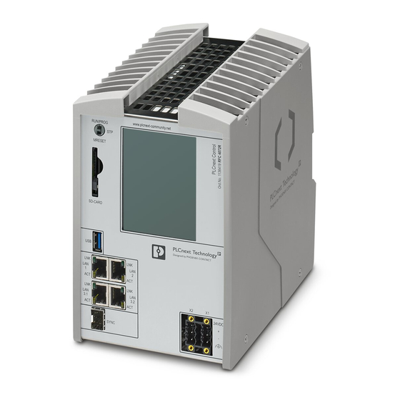
Page 24: Components Of The Controller
SYNC synchronization interface for connecting an SFP module Supply connector (connector for connecting external power supplies) Fan module (optional) The SD card and the fan module are not supplied as standard with the RFC 4072R. Please refer to the ordering data in Section 14.1. -
Page 25: Information On The Label
Description of the controller 4.8.2 Information on the label Figure 4-3 Information on the label of the RFC 4072R PHOENIX CONTACT GmbH & Co. KG Flachsmarktstr. 8 32825 Blomberg, Germany RFC 4072R Ord.No.: 1136419 (8 Block) MAC: A8.74.1D.79.02.C0 password: 12345678 HW/FW: XX/XX/XXXX S.No.: 1234567890... -
Page 26: Diagnostic And Status Indicators
RFC 4072R Diagnostic and status indicators The LNK and ACT LEDs indicate the state of the respective Ethernet interface. The LNK LED (link, green) lights up when an Ethernet connection to another network device is established. The ACT LED (activity, yellow) flashes when the Ethernet interface is trans- mitting or receiving data. -
Page 27: Fan Module
Description of the controller 4.10 Fan module In certain ambient conditions, a fan module is required to operate the controller. The fan module is not supplied as standard with the RFC 4072R. • Please refer to the ordering data in Section 14.1. -
Page 28: Touch Screen Display
RFC 4072R 4.11 Touch screen display The controller has a resistive touch screen display (referred to as “display” in the following). You can access important diagnostic and status information for the controller and its inter- faces via the various menus on the display. In addition, you can make various settings (e.g., set the IP address, specify the redundancy type, etc.). -
Page 29: Operating The Display And Navigating The Menus
Jump to the next character to the left in an input field Jump to the next character to the right in an input field • To operate the display or navigate a menu, tap the desired icon. 29 / 128 PHOENIX CONTACT 110146_en_00... -
Page 30: Home Menu
RFC 4072R 4.11.2 Home menu The home menu (A in Figure 4-6) is the start page of the display. The start pages of further menus are displayed as tiles in the home menu (B ... F in Figure 4-6). Figure 4-6... -
Page 31: Config Details" Menu
From the “CONFIG DETAILS” menu, you can access the following additional submenus: – “INFORMATION”, see Section 4.11.3.1 – “LAN SETTINGS”, see Section 4.11.3.2 – “MAINTENANCE”, see Section 4.11.3.3 – “OPTIONS”, see Section 4.11.3.4 Opening a submenu • To open a submenu, tap the desired submenu. 31 / 128 PHOENIX CONTACT 110146_en_00... -
Page 32: Config Details" Menu
RFC 4072R 4.11.3.1 “INFORMATION” submenu Figure 4-8 “CONFIG DETAILS” menu, “INFORMATION” submenu The following information is displayed in the “Information” submenu: – Item designation – Serial number – Hardware revision – FPGA revision – Firmware revision – Current date –... -
Page 33: Lan Settings
• Switch the redundant control system to the “STOP” state using the mode selector switch of the PRIMARY controller. Please note: If you are operating your application with just one RFC 4072R (“SingleMode” redun- dancy status), configure the physical IP address at the respective Ethernet interface in the “LAN SETTINGS” submenu. - Page 34 RFC 4072R Figure 4-10 “EDIT LANX” submenu (in the example: “EDIT LAN1”) • To change the “IP address”, “Subnet mask”, or “Gateway” settings, tap the correspond- ing setting. A menu opens to enter the digits. ⇒ Figure 4-11 Menu for entering the digits •...
- Page 35 If you do not wish to apply the modified setting, you can cancel the modification procedure. Canceling changes • To cancel the modification procedure, tap ⇒ The message “Nothing changed” appears in the display. Figure 4-13 “EDIT LANX” submenu, message “Nothing changed” 35 / 128 PHOENIX CONTACT 110146_en_00...
- Page 36 RFC 4072R 4.11.3.3 “MAINTENANCE” submenu Figure 4-14 “CONFIG DETAILS” menu, “MAINTENANCE” submenu You can make various maintenance settings in the “MAINTENANCE” submenu. From the “MAINTENANCE” submenu, you can access the following additional submenus: – “PLC REBOOT”, see ““PLC REBOOT” submenu”...
- Page 37 “CONFIG DETAILS” menu, “MAINTENANCE” submenu, “PLC REBOOT” submenu Restarting the controller • To restart the controller, tap ⇒ The controller will be restarted. The message “Rebooting controller...” appears in the display. Figure 4-16 Message “Rebooting controller...” 37 / 128 PHOENIX CONTACT 110146_en_00...
- Page 38 RFC 4072R Cancel operation If you do not wish to restart the controller, you can cancel this operation. • To cancel the operation, tap ⇒ The message “Nothing changed” appears in the display. Figure 4-17 “PLC REBOOT” submenu, message “Nothing changed”...
- Page 39 “FACTORY RESET” submenu, message “Reset to default! Are you sure?” • Confirm the message “Reset to default! Are you sure?”. To do this, tap ⇒ The controller is then reset to the factory default settings and restarted. 39 / 128 PHOENIX CONTACT 110146_en_00...
- Page 40 RFC 4072R Cancel operation If you do not wish to reset the controller to the factory default settings, you can cancel this operation. • To cancel the operation, tap ⇒ You are then returned to the “MAINTENANCE” submenu. The message “Nothing changed”...
- Page 41 “Speed Level”: Current rotation speed of the fan module – “Last Calibration”: Date that fan calibration was last performed. Calibrating the fan module Use the “Fan Calibration” button to initiate calibration of the fan module: 41 / 128 PHOENIX CONTACT 110146_en_00...
-
Page 42: Figure 4-23 "Fan Calibration" Submenu, Message "Fan Not Plugged
RFC 4072R • Tap “Fan Calibration”. ⇒ The “FAN CALIBRATION” submenu opens. Figure 4-22 “CONFIG DETAILS” menu, “MAINTENANCE” submenu, “FAN CONTROL DETAILS” submenu, “FAN CALIBRATION” submenu • To start fan calibration, tap ⇒ The fan module will now be calibrated. -
Page 43: Figure 4-24 "Fan Control Details" Submenu, Message "Nothing Changed
• To cancel the operation, tap ⇒ You are then returned to the “FAN CONTROL DETAILS” submenu. The message “Nothing changed” appears in the display. Figure 4-24 “FAN CONTROL DETAILS” submenu, message “Nothing changed” 43 / 128 PHOENIX CONTACT 110146_en_00... -
Page 44: Figure 4-25: "Config Details" Menu, "Maintenance" Submenu, "Mreset Reboot" Submenu
RFC 4072R “MRESET REBOOT” submenu You can switch the controller to the MRESET operating mode via the “MRESET REBOOT” submenu. Retain data is deleted. The controller is then restarted. The redundancy roles are not switched over. Please note: This setting will only take effect if it is made on the PRIMARY controller. -
Page 45: Figure 4-27 "Maintenance" Submenu, Message "Nothing Changed
If you do not wish to switch the controller to the MRESET operating mode, you can cancel this operation. • To cancel the operation, tap ⇒ You are then returned to the “MAINTENANCE” submenu. The message “Nothing changed” appears in the display. Figure 4-27 “MAINTENANCE” submenu, message “Nothing changed” 45 / 128 PHOENIX CONTACT 110146_en_00... -
Page 46: Figure 4-28 "Config Details" Menu, "Options" Submenu
RFC 4072R 4.11.3.4 “OPTIONS” submenu When not performing actions on the display, you can use a screensaver to protect the dis- play. Use the “OPTIONS” menu to specify the period of inactivity after which the screen- saver is activated. Figure 4-28 “CONFIG DETAILS”... -
Page 47: Figure 4-30 Message "Screensaver Time Set
If you wish to disable the screensaver, select the “Never” setting. • To save the modified setting, tap ⇒ The modified setting has been saved. The message “Screensaver time set” appears in the display. Figure 4-30 Message “Screensaver time set” 47 / 128 PHOENIX CONTACT 110146_en_00... -
Page 48: Figure 4-31 "Options" Submenu, Message "Nothing Changed
RFC 4072R Cancel operation If you do not wish to make any changes to the screensaver setting, you can cancel this op- eration. • To cancel the operation, tap ⇒ You are then returned to the “OPTIONS” submenu. The message “Nothing changed”... -
Page 49: Plcnext" Menu
“PLCnext Details” sub- Further information about the controller is displayed in the “PLCnext DETAILS” submenu. menu • To open the “PLCnext DETAILS” submenu, tap the “PLCnext” tile. ⇒ The “PLCnext DETAILS” submenu opens. 49 / 128 PHOENIX CONTACT 110146_en_00... - Page 50 RFC 4072R Figure 4-33 “PLCnext” menu, “PLCnext DETAILS” submenu The following information is displayed in the “PLCnext DETAILS” submenu: – “Project Name”: Name of the PLCnext Engineer project that is currently running on the controller. – “Temperature °C”: Board temperature –...
-
Page 51: Pn Control" Menu
The RFC 4072R (PROFINET controller) attempts to establish an application relation to all the configured PROFINET devices. Green The RFC 4072R (PROFINET controller) has established an ap- plication relation to at least one configured PROFINET device and is exchanging process data with this device. -
Page 52: Figure 4-35: "Pn Control" Menu, "Pn-C Details" Submenu
RFC 4072R Table 4-5 shows the possible states of the LEDs and provides a description of them. Table 4-5 Diagnostic indicators in the “PN Control” menu Color State Description No link status at the Ethernet interfaces and/or no 100 Mbit transmission and/or no full duplex mode. -
Page 53: Figure 4-36: "Pn Control" Menu, "Pn-C Details" Submenu, "Pn-C, Ar List" Submenu
Information on the possible error codes is available in the PLCnext Info Center. • Tap the “ARs with DiagInfo” button. ⇒ The “PN-C, AR Diag List” submenu opens. Figure 4-37 “PN Control” menu, “PN-C DETAILS” submenu, “PN-C, AR Diag List” sub- menu 53 / 128 PHOENIX CONTACT 110146_en_00... -
Page 54: Opc Ua" Menu
RFC 4072R 4.11.6 “OPC UA” menu In the “OPC UA” menu, you can view certain information about the OPC UA connections. Tile/start page of the menu Figure 4-38 “OPC UA” menu Status information The following status information is indicated based on the color of the “OPC UA” tile and the... -
Page 55: Figure 4-39 "Opc Ua" Menu, "Opc Ua Details" Submenu
The following information is displayed in the “OPC UA DETAILS” submenu: – “Monitored var. count”: Number of monitored OPC UA variables – “License”: Type of OPC UA license – “Sessions count”: Number of connections to OPC UA clients (sessions) 55 / 128 PHOENIX CONTACT 110146_en_00... -
Page 56: Redundancy" Menu
Table 4-7 Status information in the “Redundancy” menu Icon Color Description Gray SingleMode Operation of the application with just one RFC 4072R. A redun- dant control system cannot be created. Blue No Sync No synchronization 56 / 128 PHOENIX CONTACT... - Page 57 At least one redundancy variable is defined in the PLCnext Engineer application. – The BF LED in the “PN CONTROL” menu is deactivated (setting in PLCnext Engineer). – The controllers are connected via Ethernet interface LAN1. – Data is being synchronized. 57 / 128 PHOENIX CONTACT 110146_en_00...
-
Page 58: Figure 4-41 "Redundancy" Menu, "Redundancy Details" Submenu
RFC 4072R Table 4-7 Status information in the “Redundancy” menu Icon Color Description An error has occurred or a status message has been gener- ated. The status or error message is displayed in the last row of the “Redundancy” menu. -
Page 59: Figure 4-42: "Redundancy" Menu, "Redundancy Details" Submenu, "Action" Submenu
To save the modified setting, tap ⇒ Following successful switch-over of the redundancy roles, a corresponding message is displayed in the “ACTION” submenu, see Figure 4-43. Figure 4-43 Message following successful switch-over of the redundancy roles 59 / 128 PHOENIX CONTACT 110146_en_00... -
Page 60: Figure 4-44 "Redundancy" Menu, "Redundancy Details" Submenu, "Settings" Submenu
RFC 4072R 4.11.7.2 “SETTINGS” submenu Figure 4-44 “Redundancy” menu, “REDUNDANCY DETAILS” submenu, “SETTINGS” submenu The redundancy type that is currently set for the controller is displayed locally in the “SET- TINGS” submenu. You can use to modify the redundancy type of controller. - Page 61 “Second”. Setting for operation with It is possible for you to operate your application with just one RFC 4072R. However, if just one controller you do this, you cannot create a redundant control system and will have to operate your application without redundancy properties.
-
Page 62: Figure 4-46: "Redundancy" Menu, "Redundancy Details" Submenu, "Redundancy Status" Submenu
RFC 4072R 4.11.7.3 “REDUNDANCY STATUS” submenu Figure 4-46 “Redundancy” menu, “REDUNDANCY DETAILS” submenu, “REDUN- DANCY STATUS” submenu The following information about the status of the redundant control system is displayed in the “REDUNDANCY STATUS” submenu: – “Switchover Count”: Number of times the redundancy roles have been switched over since the last restart of the redundant control system. -
Page 63: Interfaces
You can use the USB flash drive to perform firmware updates. In addition, you can access the inserted USB flash drive from your application via the PLCnext Engineer file function blocks. Figure 4-47 USB interface of the RFC 4072R 63 / 128 PHOENIX CONTACT 110146_en_00... -
Page 64: Ethernet
RFC 4072R 4.12.2 Ethernet The RFC 4072R has four Ethernet interfaces (1 in Figure 4-48). Figure 4-48 Ethernet interfaces of the RFC 4072R Interfaces Description LAN1 1 x Ethernet 10/100/1000Base-T(X); PROFINET controller interface (preconfigured) LAN2 1 x Ethernet 10/100/1000Base-T(X) LAN3.1/LAN3.2... -
Page 65: Contact Assignment Of The Ethernet Interfaces Depending On
Please note: If you later wish to operate your application with two RFC 4072R controllers, the pre- set IP addresses at LAN1, LAN2, and LAN3.1/LAN3.2 will be used as system IP ad- dresses. The physical IP addresses at the Ethernet interfaces will then be set automatically, as described in the “Redundancy operation”... -
Page 66: Figure 4-50: Automatic Setting Of The Physical Ip Addresses Based On A System Address
RFC 4072R The physical IP addresses are set automatically as follows: System IP address: 192.168.1.x (x = 0 ... 252) Physical IP address of the first controller (redun- 192.168.1.x+1 dancy type “First”): Physical IP address of the second controller (re- 192.168.1.x+2... -
Page 67: Sync Interface
An SFP module can be connected to the SYNC interface (1 in Figure 4-51) in order to con- nect two RFC 4072R controllers via fiber optics and thus create a redundant control system. The coupled RFC 4072R controllers are synchronized with each other via the SYNC inter- face. -
Page 68: Mode Selector Switch
RFC 4072R 4.13 Mode selector switch Figure 4-52 Mode selector switch RUN/PROG MRESET The mode selector switch is used to define the operating state of the controller. The RUN/PROG and STOP positions have a latching function, and the MRESET position has a non-latching function. -
Page 69: Mounting Hardware
Earthing and Shielding PROFIBUS and PROFINET” document for the grounding concept in particular. • You can download both documents at www.profinet.com. Alternatively, you can obtain the documents from Phoenix Contact. To do this, please contact Phoenix Contact. 69 / 128... -
Page 70: Mounting The Fan Module
RFC 4072R Please observe the following notes when using a shield connection clamp: • Make sure that the cable shields for Ethernet are correctly secured in the connec- tors and when routing a cable through a control cabinet. • Only use shielded data cables. As much of the cable shield as possible must be connected to the ground on both sides. - Page 71 Mounting the fan module Figure 5-1 Mounting the fan module • Mount the fan module on the RFC 4072R before you mount the controller. • Position the fan module on the bottom of the controller, as illustrated in Figure 5-1.
-
Page 72: Mounting The Controller
Recommended: • At an altitude of 0 m ... 2000 m above mean sea level, operate the RFC 4072R with a fan module at an ambient temperature above 50°C. The RFC 4072R must always be operated with the fan module in the following ambi- ent conditions: –... - Page 73 (incl. end brackets) in the standard mounting po- sition and the maximum distance between the DIN rail fastening points (160 mm). Figure 5-3 Mounted controller in the standard mounting position 73 / 128 PHOENIX CONTACT 110146_en_00...
-
Page 74: Inserting The Sd Card
PLCnext Control product family from Phoenix Contact. If you format the SD card, certain information on the SD card that is required for use with Phoenix Contact devices will be lost. After formatting, you can no longer use the SD card to operate the controller. -
Page 75: Connecting And Wiring The Hardware
Overload range without fall-back charac- curve teristic curve Overload range Overload range with fall-back without fall-back characteristic curve characteristic curve [ ] V [ ] A 1.5 x I 1.1 x I 2.4 x I 75 / 128 PHOENIX CONTACT 110146_en_00... -
Page 76: Wiring And Connecting The Power Supplies
Each connection for the power supply is monitored internally in the device. Temporary voltage interruptions are bridged by the built-in voltage buffering. NOTE: Startup of the RFC 4072R not ensured Correct device startup will not be ensured if you switch on the supply voltage too soon after a voltage failure. -
Page 77: Connecting The Usb Flash Drive
Connecting the USB flash drive • Disconnect the power to the controller. • Plug the USB flash drive into the USB interface on the controller. • Switch on the supply voltage of the RFC 4072R. 77 / 128 PHOENIX CONTACT 110146_en_00... -
Page 78: Connecting Ethernet
RFC 4072R Connecting Ethernet • Connect the Ethernet cable to the desired Ethernet interface on the RFC 4072R. LAN1, LAN2, LAN3.1, LAN3.2: • Use Ethernet cables in accordance with CAT5 of IEEE 802.3 for operation with up to 100 Mbps. -
Page 79: Connecting The Sfp Module And Fo Cables
Connecting the SFP module and FO cables Two RFC 4072R controllers are connected together to create a redundant system. To cou- ple the two controllers, first connect an SFP module to each RFC 4072R. Then connect the two devices together via a FO cable. - Page 80 Figure 6-7 Connecting FO cables • Push the first connector of the FO cable into the SFP module on one of the RFC 4072R controllers until the connector audibly snaps into place. • Push the second connector of the FO cable into the SFP module on the other RFC 4072R until the connector audibly snaps into place.
-
Page 81: Startup
For information on configuring the IP addresses in the PLCnext Engineer software, please refer to Section 7.2.5. Information on configuring the IP addresses via the controller WBM is available in the PLCnext Info Center. 81 / 128 PHOENIX CONTACT 110146_en_00... -
Page 82: Preparing The Second Controller
Please note: If you later wish to operate your application with two RFC 4072R controllers, the pre- set IP addresses at LAN1, LAN2, and LAN3.1/LAN3.2 will be used as system IP ad- dresses. The physical IP addresses at the Ethernet interfaces will then be set automatically. -
Page 83: Startup With Plcnext Engineer
The software can be downloaded at phoenixcontact.net/product/1046008. • Download the software (version ≥ 2022.0 LTS) onto your PC. • Double-click the *.exe file to start installation. • Follow the instructions in the installation wizard. 83 / 128 PHOENIX CONTACT 110146_en_00... -
Page 84: User Interface
RFC 4072R 7.2.2 User interface Figure 7-1 PLCnext Engineer user interface Menu bar Toolbar “PLANT” area Editor area “COMPONENTS” area Cross-functional area Status bar “PLANT” area All of the physical and logical components of your application are mapped in the form of a hierarchical tree structure in the “PLANT”... - Page 85 Shows the current connection status between the controller and PLCnext Engineer. – RECYCLE BIN: Elements that have recently been deleted from the “PLANT” or “COMPONENTS” areas are moved to the recycle bin. Deleted elements can be restored from here, if needed. 85 / 128 PHOENIX CONTACT 110146_en_00...
-
Page 86: Creating A New Project
Open the “File, New Project” menu. Figure 7-2 “File, New Project” menu To add the RFC 4072R as a controller in the “PLANT” area, you first need to import the “High-availability Controller” library within the “COMPONENTS” area: • In the “COMPONENTS” area, open the “Libraries (x)” section. - Page 87 Phoenix Contact, Remote Field Controller, High-availability Controller, RFC 4072R”. Figure 7-5 RFC 4072R in the “COMPONENTS” area • Using drag and drop, move the RFC 4072R to the “Project” node in the “PLANT” area. ⇒ You have created an empty RFC 4072R project. •...
-
Page 88: Setting The Ip Address Range
RFC 4072R 7.2.4 Setting the IP address range • Double-click on the “Project (x)” node in the “PLANT” area. ⇒ The “Project” editor group opens. • Select the “Settings” editor. • Set the desired IP address range and the subnet mask for the project. -
Page 89: Optional: Setting (System) Ip Addresses
Optional: Setting (system) IP addresses • Double-click on the controller node in the “PLANT” area. The controller editor group opens. • Select the “Settings” editor. • Select the “Ethernet” view. Figure 7-7 Setting (system) IP addresses 89 / 128 PHOENIX CONTACT 110146_en_00... - Page 90 RFC 4072R For operation of a redun- If you are operating a redundant control system with two controllers, set the system IP ad- dress at the respective Ethernet interface. You cannot set the physical IP address of the dant control system controllers at the respective Ethernet interface (“Physical IP of First Controller”...
- Page 91 The “Physical IP of First Controller” and “Physical IP of Second Controller” input fields are not relevant for operation in “SingleMode”. ⇒ PLCnext Engineer assigns the manually set IP addresses to the controller as soon as a connection is established to the controller (see Section 7.2.6). 91 / 128 PHOENIX CONTACT 110146_en_00...
-
Page 92: Connecting To The Primary Controller
RFC 4072R 7.2.6 Connecting to the PRIMARY controller To be able to transfer a project to the PRIMARY controller, you must first connect PLCnext Engineer to the PRIMARY controller. To do this, proceed as follows: • Double-click on the “Project (x)” node in the “PLANT” area. - Page 93 PLCnext Engineer to the controller. ⇒ The “SECURE DEVICE LOGIN” dialog opens. Figure 7-11 “SECURE DEVICE LOGIN” dialog • Enter your user name and password. In the delivery state, the following access data is preset with administrator rights: 93 / 128 PHOENIX CONTACT 110146_en_00...
- Page 94 RFC 4072R User name: admin Password: printed on the controller (see Figure 4-3) icon next to the controller node in the “PLANT” area indicates that connection was successful. Figure 7-12 Successful connection to the controller 94 / 128 PHOENIX CONTACT...
-
Page 95: Further Startup Steps
The system redundancy data hold time must be ≥ 200 ms. Recommended: • Set the system redundancy data hold time as follows: System redundancy data hold time = 100 ms + 4 x PROFINET device update time 95 / 128 PHOENIX CONTACT 110146_en_00... - Page 96 RFC 4072R Figure 7-13 shows the set PROFINET device update time. Figure 7-13 PROFINET device update time Figure 7-14 shows the system redundancy data hold time. Figure 7-14 PROFINET system redundancy: data hold time 96 / 128 PHOENIX CONTACT 110146_en_00...
- Page 97 Always enter the name “SyncTask” for the cyclic task in the “Name” input field (see Figure 7-15). Only then will the cyclic task be synchronized between the controllers in redundancy operation. Figure 7-15 “SyncTask” cyclic task 97 / 128 PHOENIX CONTACT 110146_en_00...
-
Page 98: System Variables And Status Information
RFC 4072R System variables and status information Information on the system variables is available in the PLCnext Info Center. 98 / 128 PHOENIX CONTACT 110146_en_00... -
Page 99: Web-Based Management (Wbm)
Fan Control – Web Services – Date and Time – “Security” area: – User Authentication – Certificate Authentication – LDAP Configuration – Firewall – “Administration” area: – Firmware Update – PLCnext Apps – License Management 99 / 128 PHOENIX CONTACT 110146_en_00... -
Page 100: 10 Removing Hardware
RFC 4072R 10 Removing hardware 10.1 Safety notes NOTE: Electrostatic discharge Electrostatic discharge can damage or destroy components. When handling the de- vice, observe the necessary safety precautions against electrostatic discharge (ESD) in accordance with EN 61340-5-1 and IEC 61340-5-1. -
Page 101: Removing The Usb Flash Drive
NOTE: Device defect due to inserting/removing the USB flash drive during op- eration If you insert or remove the USB flash drive during operation, this can cause a device defect on the RFC 4072R. • Disconnect the power to the controller before inserting or removing the USB flash drive. -
Page 102: Removing The Ethernet Connectors
RFC 4072R 10.4 Removing the Ethernet connectors Figure 10-3 Removing the Ethernet connectors • Release the RJ45 connectors by pressing on the snap-in latch and remove the Ethernet connectors. 10.5 Removing the FO cables Figure 10-4 Removing the FO cables •... -
Page 103: Removing The Sfp Module
Removing the SFP module Figure 10-5 Removing the SFP module • Turn the release latch on the SFP model away from the SFP module (A). • Remove the SFP module from the controller (B). 103 / 128 PHOENIX CONTACT 110146_en_00... -
Page 104: Removing The Sd Card
PLCnext Control product family from Phoenix Contact. If you format the SD card, certain information on the SD card that is required for use with Phoenix Contact devices will be lost. After formatting, you can no longer use the SD card to operate the controller. -
Page 105: Removing The Controller
• Before removing the fan module, switch off the controller and remove it from the DIN rail. Figure 10-8 Removing the fan module • Remove the four M4 screws. • Remove the fan module from the controller. 105 / 128 PHOENIX CONTACT 110146_en_00... -
Page 106: 11 Device Replacement, Device Defects, And Repairs
Connect the SFP module and the FO cable. • Connect the power supplies. • Switch on the power supplies. ⇒ When the RFC 4072R is fully initialized, both controllers are synchronized with each other via the SYNC interface. 106 / 128 PHOENIX CONTACT 110146_en_00... -
Page 107: Replacing The Fan Module
Once the BACKUP controller is fully initialized, the PRIMARY and BACKUP controllers are synchronized with each other. All the application-specific contents of the PRIMARY controller SD card are transferred to the BACKUP controller SD card. 107 / 128 PHOENIX CONTACT 110146_en_00... -
Page 108: Device Defects And Repairs
Device defects and repairs Repairs may only be carried out by Phoenix Contact. • Send defective devices back to Phoenix Contact for repair or to receive a replacement device. • We strongly recommend using the original packaging to return the product. -
Page 109: 12 Maintenance, Decommissioning, And Disposal
• Remove the SD card. • Physically destroy the SD card, e.g., by cutting up the SD card. • Dispose of the irreparably damaged SD card in accordance with the applicable national regulations. 109 / 128 PHOENIX CONTACT 110146_en_00... -
Page 110: 13 Troubleshooting
DifferentPlcTypes The remote controller is not an RFC • Replace the remote controller with 4072R controller. an RFC 4072R controller. DifferentFirmwareVersions Different firmware versions are in- • Make sure that the same firmware stalled on the controllers. - Page 111 Restart the BACKUP controller. was reported by the BACKUP con- • If the message occurs again, con- troller. tact Phoenix Contact. SetIpConfigFailed During synchronization, an error oc- • Make sure that there is a 1-1 con- curred on the BACKUP controller...
- Page 112 RFC 4072R Table 13-1 Possible status and error messages in the “Redundancy” menu Digit Status or error message Description Remedy StopBackupPlcFailed BACKUP controller: An error oc- • Make sure that there is a 1-1 con- curred when switching to the STOP nection between the first and sec- operating mode.
-
Page 113: 14 Ordering Data And Technical Data
Ordering data and technical data 14 Ordering data and technical data 14.1 Ordering data Description Type Item no. Pcs./Pkt. High-availability PLCnext controller with redundancy RFC 4072R 1136419 functionality Accessories Accessories are available at: phoenixcontact.net/product/1136419 Documentation Additional documentation is available at: phoenixcontact.net/product/1136419... -
Page 114: Technical Data
RFC 4072R 14.2 Technical data Dimensions (nominal sizes in mm) External dimensions (Width x Height x Depth) 122 mm x 182 mmx 173 mm (without fan module) 122 mm x 220 mmx 173 mm (With fan module) General data Weight 2730 g (Without fan module) 2960 g (With fan module) - Page 115 128 kByte (Input and output data) PROFINET Device function PROFINET-Controller Number of supported devices max. 256 Vendor ID 00B0 / 176 Protective circuit Surge protection of the supply voltage electronic Polarity reversal protection of the supply voltage electronic 115 / 128 PHOENIX CONTACT 110146_en_00...
- Page 116 RFC 4072R Device supply WARNING: Loss of electrical safety and the safety function when using unsuitable power supplies The device is designed exclusively for protective extra-low voltage (PELV) operation according to EN 60204-1. Only protective extra-low voltages in accordance with the listed standard may be used for the supply.
- Page 117 This is a Class A item of equipment. When using the equipment in residential areas, it may cause radio inter- ference. In this case, the operator may be required to implement appropriate measures and to pay the resulting costs. Approvals For the latest approvals, refer to: phoenixcontact.net/product/1136419 117 / 128 PHOENIX CONTACT 110146_en_00...
-
Page 118: A Appendix
RFC 4072R A Appendix Updating the firmware via the shell Information on firmware updates via the shell is available in the PLCnext Info Center. Shell commands for controlling the firmware Information on controlling the firmware (start, stop, restart) via shell commands is... - Page 119 B Appendix for document lists List of figures Section 3 Figure 3-1: Redundant control system with two RFC 4072R controllers ....12 Figure 3-2: Marking a variable as redundant in PLCnext Engineer ....... 13 Figure 3-3: Ideal typical system behavior .............. 14...
- Page 120 Figure 4-46: “Redundancy” menu, “REDUNDANCY DETAILS” submenu, “REDUNDANCY STATUS” submenu ..........62 Figure 4-47: USB interface of the RFC 4072R ............63 Figure 4-48: Ethernet interfaces of the RFC 4072R ..........64 Figure 4-49: Contact assignment of an Ethernet interface ........64...
- Page 121 “File, New Project” menu ..............86 Figure 7-3: Context menu, “Add Library...” ............86 Figure 7-5: RFC 4072R in the “COMPONENTS” area .......... 87 Figure 7-6: Setting the IP address range ............... 88 Figure 7-7: Setting (system) IP addresses ............89 Figure 7-8: Selecting the network card ..............
- Page 122 RFC 4072R Section 10 Figure 10-1: Removing the supply connectors ............100 Figure 10-2: Removing the USB flash drive ............101 Figure 10-3: Removing the Ethernet connectors ........... 102 Figure 10-4: Removing the FO cables ..............102 Figure 10-5: Removing the SFP module ............... 103 Figure 10-6: Removing the SD card ..............
- Page 123 ................65 Table 4-8: Example IP addresses ................. 66 Table 4-9: Controller operating modes ..............68 Section 13 Table 13-1: Possible status and error messages in the “Redundancy” menu ..110 123 / 128 PHOENIX CONTACT 110146_en_00...
- Page 124 RFC 4072R Index Symbols Diagnostic and status indicators ......... 26 Display “CONFIG DETAILS” menu .......... 31 Cleaning .............. 109 “INFORMATION”........... 32 Operation .............. 29 “LAN SETTINGS” ..........33 Screensaver ............46 “MAINTENANCE”..........36 Disposal “OPTIONS”............46 Controller............. 109 “OPC UA” menu ............54 Packaging ............
- Page 125 Removing ............101 Data synchronization times ........13 Description ............12 Features ..............12 Web-based management (WBM) ....... 99 Function ..............13 Redundancy status..........14 Setup..............12 Startup..............12 System behavior............ 14 Repairs ..............108 125 / 128 PHOENIX CONTACT 110146_en_00...
- Page 126 RFC 4072R 126 / 128 PHOENIX CONTACT 110146_en_00...
- Page 127 The receipt of technical documentation (in particular user documentation) does not constitute any further duty on the part of Phoenix Contact to furnish information on modifications to products and/or technical documentation. You are responsible to verify the suitability and intended use of the products in your specific application, in particular with regard to observing the applicable standards and regulations.
- Page 128 Should you have any suggestions or recommendations for improvement of the contents and layout of our manuals, please send your comments to: tecdoc@phoenixcontact.com 128 / 128 PHOENIX CONTACT GmbH & Co. KG • Flachsmarktstraße 8 • 32825 Blomberg • Germany phoenixcontact.com...
- Page 130 PHOENIX CONTACT GmbH & Co. KG Flachsmarktstraße 8 32825 Blomberg, Germany Phone: +49 5235 3-00 Fax: +49 5235 3-41200 E-mail: info@phoenixcontact.com phoenixcontact.com...
Need help?
Do you have a question about the RFC 4072R and is the answer not in the manual?
Questions and answers