Sign In
Upload
Manuals
Brands
Phoenix Contact Manuals
Controller
1136419
Phoenix Contact 1136419 Controller Manuals
Manuals and User Guides for Phoenix Contact 1136419 Controller. We have
1
Phoenix Contact 1136419 Controller manual available for free PDF download: User Manual
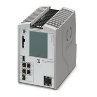
Phoenix Contact 1136419 User Manual (130 pages)
Remote Field Controller
Brand:
Phoenix Contact
| Category:
Controller
| Size: 11 MB
Table of Contents
Section 1
3
Table of Contents
3
For Your Safety
7
Identification of Warning Notes
7
Qualification of Users
7
Field of Application of the Product
8
Intended Use
8
Product Changes
8
Safety Notes
8
Security in the Network
9
Unpacking
10
Transport
10
Storage
10
Transport, Storage, and Unpacking
10
Checking the Delivery
11
The Redundant Control System
12
General Description
12
Data Synchronization Time Depending on the Amount of
13
System Behavior and Redundancy Status
14
Ideal Typical System Behavior
14
No Sync" Redundancy Status: Causes
15
Followup Sync" Redundancy Status: Causes
15
System Behavior in the Event of no Synchronization Connec- Tion
15
System Behavior on Switching the PRIMARY Controller to the STOP Operating Mode
15
Singlemode" Redundancy Status: Cause
16
Causes of Switch-Over
17
Description of the Controller
18
General Description of the Controller
18
System IP Addresses
18
Licensing Information on Open-Source Software
20
Requesting the Source Code
20
Hardware and Software Requirements
21
Directory Structure
22
Directory Structure of the File System
22
Using SFTP to Access the File System
22
Firewall
23
Administrator Password
23
Components of the Controller
24
Connection and Operating Elements
24
Information on the Label
25
Diagnostic and Status Indicators
26
Fan Module
27
Touch Screen Display
28
Operating the Display and Navigating the Menus
29
Home Menu
30
CONFIG DETAILS" Menu
31
Information
31
Maintenance
31
Options
31
Controller
31
CONFIG DETAILS" Menu
32
Lan Settings
33
Changing the System IP Address
33
Figure 4-23 "FAN CALIBRATION" Submenu, Message "Fan Not Plugged
42
Figure 4-24 "FAN CONTROL DETAILS" Submenu, Message "Nothing Changed
43
Figure 4-25: "CONFIG DETAILS" Menu, "MAINTENANCE" Submenu, "MRESET REBOOT" Submenu
44
Figure 4-26: "MRESET REBOOT" Submenu, Message "Remove Retain Data and Reboot
44
Figure 4-27 "MAINTENANCE" Submenu, Message "Nothing Changed
45
Figure 4-28 "CONFIG DETAILS" Menu, "OPTIONS" Submenu
46
Figure 4-29: "CONFIG DETAILS" Menu, "OPTIONS" Submenu, "SCREENSAVER" Submenu
46
Figure 4-30 Message "Screensaver Time Set
47
Figure 4-31 "OPTIONS" Submenu, Message "Nothing Changed
48
Status Information in the "Plcnext" Menu
49
Figure 4-32 "Plcnext" Menu, Start Page
49
Plcnext" Menu
49
PN Control" Menu
51
Figure 4-34 "PN Control" Menu, Start Page
51
Status Information in the "PN Control" Menu
51
Figure 4-35: "PN Control" Menu, "PN-C DETAILS" Submenu
52
Diagnostic Indicators in the "PN Control" Menu
52
Pn-C Details
52
Figure 4-36: "PN Control" Menu, "PN-C DETAILS" Submenu, "PN-C, AR List" Submenu
53
Figure 4-37: "PN Control" Menu, "PN-C DETAILS" Submenu, "PN-C, AR Diag List" Submenu
53
Opc Ua Details
54
Figure 4-38 "OPC UA" Menu
54
Status Information in the "OPC UA" Menu
54
OPC UA" Menu
54
Figure 4-39 "OPC UA" Menu, "OPC UA DETAILS" Submenu
55
Redundancy" Menu
56
Figure 4-40 "Redundancy" Menu
56
Status Information in the "Redundancy" Menu
56
Figure 4-41 "Redundancy" Menu, "REDUNDANCY DETAILS" Submenu
58
Redundancy Details
58
Figure 4-42: "Redundancy" Menu, "REDUNDANCY DETAILS" Submenu, "ACTION" Submenu
59
Figure 4-43: Message Following Successful Switch-Over of the Redundancy Roles
59
Figure 4-44 "Redundancy" Menu, "REDUNDANCY DETAILS" Submenu, "SETTINGS" Submenu
60
Figure 4-45 Message "Redundancy Type Changed. Restart
60
Figure 4-46: "Redundancy" Menu, "REDUNDANCY DETAILS" Submenu, "REDUNDANCY STATUS" Submenu
62
Interfaces
63
Usb
63
Figure 4-47 USB Interface of the RFC 4072R
63
Ethernet
64
Figure 4-48: Ethernet Interfaces of the RFC 4072R
64
Figure 4-49: Contact Assignment of an Ethernet Interface
64
Ethernet Interfaces
64
Contact Assignment of the Ethernet Interfaces Depending on
65
Physical IP Addresses
66
Figure 4-50: Automatic Setting of the Physical IP Addresses Based on a System Address
66
Example IP Addresses
66
SYNC Interface
67
Figure 4-51 SYNC Interface
67
Mode Selector Switch
68
Figure 4-52 Mode Selector Switch
68
Mounting Hardware
69
Safety Notes
69
Mounting the Fan Module
70
Mounting the Controller
72
Inserting the SD Card
74
Connecting and Wiring the Hardware
75
Power Supply
75
Sizing of the Power Supply
75
Connecting and Wiring
75
Wiring and Connecting the Power Supplies
76
Connecting the USB Flash Drive
77
Connecting Ethernet
78
Connecting the SFP Module and FO Cables
79
Preparing the First Controller
81
Startup Steps on the Device
81
Startup
81
Preparing the Second Controller
82
Preparing the Controller for "Singlemode
82
Startup with Plcnext Engineer
83
Installing Plcnext Engineer
83
User Interface
84
Creating a New Project
86
Setting the IP Address Range
88
Optional: Setting (System) IP Addresses
89
Connecting to the PRIMARY Controller
92
Further Startup Steps
95
Special Features
95
System Variables and Status Information
98
Web-Based Management (WBM)
99
10 Removing Hardware
100
Safety Notes
100
Removing the Supply Connectors
100
Figure 10-1 Removing the Supply Connectors
100
Figure 10-2 Removing the USB Flash Drive
101
Removing the USB Flash Drive
101
Removing the Ethernet Connectors
102
Removing the FO Cables
102
Figure 10-3 Removing the Ethernet Connectors
102
Figure 10-4 Removing the FO Cables
102
Removing the SFP Module
103
Figure 10-5 Removing the SFP Module
103
Removing the SD Card
104
Figure 10-6: Removing the SD Card
104
Figure 10-8 Removing the Fan Module
105
Figure 10-7 Removing the Controller
105
Removing the Fan Module
105
Removing the Controller
105
11 Device Replacement, Device Defects, and Repairs
106
Device Replacement
106
Replacing the Controller
106
Replacing the Fan Module
107
Replacing the SD Card
107
Device Defects and Repairs
108
Device Defect
108
Controller Disposal
109
Maintenance
109
Decommissioning and Disposal
109
12 Maintenance, Decommissioning, and Disposal
109
13 Troubleshooting
110
14 Ordering Data and Technical Data
113
Ordering Data
113
Technical Data
114
A Appendix
118
A 1 Updating the Firmware Via the Shell
118
A 2 Shell Commands for Controlling the Firmware
118
A 3 Replacing the HTTPS Certificate
118
Section 2
120
Advertisement
Advertisement
Related Products
Phoenix Contact CONTACTRON CSS 1.5-1/3-EMC
Phoenix Contact CONTACTRON CSS 1.5-3/3-EMC
Phoenix Contact 1201135
Phoenix Contact 1201494
Phoenix Contact 1201509
Phoenix Contact 1201520
Phoenix Contact 1201613
Phoenix Contact 1201642
Phoenix Contact 1201679
Phoenix Contact 1201695
Phoenix Contact Categories
Controller
Switch
Control Unit
Power Supply
Media Converter
More Phoenix Contact Manuals
Login
Sign In
OR
Sign in with Facebook
Sign in with Google
Upload manual
Upload from disk
Upload from URL