Table of Contents
Advertisement
Quick Links
Advertisement
Table of Contents

Related Manuals for Eaton SmartWire-DT EU5C-SWD-DP


Summary of Contents for Eaton SmartWire-DT EU5C-SWD-DP
- Page 1 Manual 01/13 MN120001Z-EN SmartWire-DT® Gateway EU5C-SWD-DP...
- Page 2 No part of this manual may be reproduced, stored in a retrieval system, or transmit- ted in any form or by any means, electronic, mechanical, photocopying, micro-film- ing, recording or otherwise, without the prior written permission of Eaton Industries GmbH, Bonn.
- Page 3 Danger! Dangerous electrical voltage! Before commencing the installation • Disconnect the power supply of the device. • Ensure a reliable electrical isolation of the low voltage for the 24 V supply. Only use power supply units complying • Ensure that devices cannot be accidentally retriggered with IEC 60 364-4-41 (VDE 0100 Part 410) or HD 384.4.41 S2.
-
Page 5: Table Of Contents
Versions of description files ............29 Take XSoft-CoDeSys-2 into operation ........31 Installing the GSD file in XSoft-CoDeSys-2 ........31 Select field bus master ..............32 Select gateway as field bus module ..........32 SmartWire-DT Gateway EU5C-SWD-DP 01/13 MN120001Z-EN www.eaton.eu... - Page 6 8.2.2 General ambient conditions ............76 8.2.3 Power supply ................77 8.2.4 SmartWire-DT®................78 8.2.5 Field bus interface PROFIBUS-DP ..........79 8.2.6 Diagnostics interface ..............79 Compatible SWD module types........... 80 Index ................... 83 SmartWire-DT Gateway EU5C-SWD-DP 01/13 MN120001Z-EN www.eaton.eu...
-
Page 7: About This Manual
SmartWire-DT gateways for various field buses, this version only covers one single SmartWire-DT gateway. The following table show the most important changes that have been made in terms of content: Publication date Page(s) Subject Modi- Omit fied 01/13 „"Online replacement" device parameter“ SmartWire-DT Gateway EU5C-SWD-DP 01/13 MN120001Z-EN www.eaton.eu... -
Page 8: Target Group
0.4 Device designations and abbreviations • GDS - device master data Following designations XSoft-CoDeSys-2 are used: • Module - SWD module • Station - Coordinator • Station address - Address of the field bus module SmartWire-DT Gateway EU5C-SWD-DP 01/13 MN120001Z-EN www.eaton.eu... -
Page 9: Reading Conventions
Indicates useful tips. ▶ Indicates instructions to be followed. For greater clarity, the name of the current chapter and the name of the cur- rent section are shown at the top of each page. SmartWire-DT Gateway EU5C-SWD-DP 01/13 MN120001Z-EN www.eaton.eu... - Page 10 0 About this Manual 0.5 Reading conventions SmartWire-DT Gateway EU5C-SWD-DP 01/13 MN120001Z-EN www.eaton.eu...
-
Page 11: Smartwire-Dt Gateway® Eu5C-Swd-Dp
D-sub socket . The SmartWire-DT line, along with its modules, is con- nected to the gateway. The ribbon cable, with the SWD modules and all con- nection components - such as blade terminals and external device plugs - is referred to as the "SWD line." SmartWire-DT Gateway EU5C-SWD-DP 01/13 MN120001Z-EN www.eaton.eu... -
Page 12: Versions
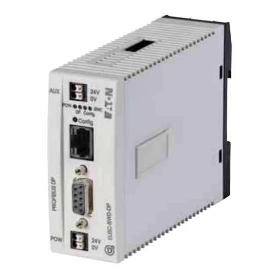
Power supply, 24 V DC POW b Fieldbus interface c Diagnostics interface d Configuration buttons e LED indicators: POW, DP, Config, SWD f Power supply, 24 V DC AUX g SmartWire-DT connection h Dip switch for address setting SmartWire-DT Gateway EU5C-SWD-DP 01/13 MN120001Z-EN www.eaton.eu... -
Page 13: Important Data For Engineering
PROFIBUS-DP SUB-D socket Signal RxD/TxD-P CNTR-P DGND VP (+5 V DC) RxD/TxD-N Figure 3: Pinout for the PROFIBUS-DP terminal socket on the gateway SmartWire-DT Gateway EU5C-SWD-DP 01/13 MN120001Z-EN www.eaton.eu... -
Page 14: Baud Rate
The unit will adapt to the field bus master's Baud rate automatically. 1.4.3 Valid device field bus addresses Data bus Address Address setting with Valid address range dip switch PROFIBUS-DP Slave address 2 - 8 1 - 125 SmartWire-DT Gateway EU5C-SWD-DP 01/13 MN120001Z-EN www.eaton.eu... -
Page 15: Installation
Use DIP switches 2–8 to set the PROFIBUS module address. For a list of valid addresses, refer to → Section “1.4.3 Valid device field bus addresses”, page 10. DIP Switch Description Setting the gateway's field bus address to a value of 18 SmartWire-DT Gateway EU5C-SWD-DP 01/13 MN120001Z-EN www.eaton.eu... -
Page 16: Activating The Bus Termination Resistor For Profibus-Dp
For ease of wiring, leave a clearance of at least 3 cm between the device ter- minals and the wall or adjacent devices. 30 mm 30 mm (1.18”) (1.18”) Figure 5: Vertical mounting Figure 6: Horizontal mounting SmartWire-DT Gateway EU5C-SWD-DP 01/13 MN120001Z-EN www.eaton.eu... -
Page 17: Mounting The Eu5C-Swd-Dp Gateway On A Top-Hat Rail
For screw fixing, you will need two fixing brackets that can be used on the back of the EU5C-SWD-DP gateway. Fixing brackets ZB4-101-GF1 are avail- able as accessories. Figure 8: Inserting a fastening Figure 9: EU5C-SWD-DP screw fixing bracket SmartWire-DT Gateway EU5C-SWD-DP 01/13 MN120001Z-EN www.eaton.eu... -
Page 18: Potential Relationship Between The Components
In this way the various mod- ules in the SmartWire-DT system will not be electrically isolated from one another. The field bus and the SmartWire-DT system are electrically isolated from one another. SmartWire-DT Gateway EU5C-SWD-DP 01/13 MN120001Z-EN www.eaton.eu... -
Page 19: Connecting The Power Supply
The manual "SmartWire-DT The System", MN05006002Z-EN, contains detailed calculation examples. 24 V DC Figure 10: Connection of power supply SmartWire-DT Gateway EU5C-SWD-DP 01/13 MN120001Z-EN www.eaton.eu... - Page 20 Cable protection for cable AWG 24 in accordance with UL 508 and CSA- 22.2 no. 14: • Miniature circuit-breaker 24 V DC rated operational current 2 A; trip type B or • Fuse 2 A SmartWire-DT Gateway EU5C-SWD-DP 01/13 MN120001Z-EN www.eaton.eu...
-
Page 21: Connect Smartwire-Dt
Detailed instructions explaining how to assemble a SmartWire- DT external device plug (SWD4-8SF2-5) onto an 8-pin Smart- Wire-DT cable can be found in "SmartWire-DT The System", MN05006002Z-EN, in the "Assembling external device plug SWD4-8SF2-5" section. SWD4-…LF… SWD4-8MF Figure 11: Connection SmartWire-DT SmartWire-DT Gateway EU5C-SWD-DP 01/13 MN120001Z-EN www.eaton.eu... -
Page 22: Connect Field Bus
To attach the PROFIBUS-DP cable, a special PROFIBUS-DP plug (e.g. ZB4- 209-DS2) is needed. This has the necessary wiring for fault-free operation at up to 12 Mbit/sec. ▶ Connect the PROFIBUS-DP cable with the PROFIBUS-DP plug to the gateway's field bus interface. SmartWire-DT Gateway EU5C-SWD-DP 01/13 MN120001Z-EN www.eaton.eu... -
Page 23: Connecting The Diagnostics Interface
Table 1: Programming cable for the connection to a PC Device Programming cable Baud rate EU5C-SWD-DP EU4A-RJ45-CAB1 – EU4A-RJ45-USB-CAB1 38.4 kBaud RS232 – – – – – Figure 13: Configuration of the serial interface. SmartWire-DT Gateway EU5C-SWD-DP 01/13 MN120001Z-EN www.eaton.eu... -
Page 24: Wiring In Accordance With Emc Requirements
(cable, connection of the bus connectors, etc.), • Using shielding for top-hat rail for mounting plate ZB4-102-KS1 ZB4-102-KS1 KLBü 3-8 SC FM 4/TS 35 (Weidmüller) (Weidmüller) Figure 14: Field bus shielded by using a shield SmartWire-DT Gateway EU5C-SWD-DP 01/13 MN120001Z-EN www.eaton.eu... -
Page 25: Commissioning
SWD line. SmartWire-DT's response to any detected discrepancies will depend on how the device parameters for the SWD coor- dinator and the SWD modules have been configured → Chapter 7 "What you need to know about SmartWire-DT®“, page 57. SmartWire-DT Gateway EU5C-SWD-DP 01/13 MN120001Z-EN www.eaton.eu... -
Page 26: Reading Of Target Configuration
The SWD-LED on the gateway begins to flash orange. The SWD-LEDs on the SmartWire-DT modules also flash. All modules are addressed in sequence, the complete configuration is stored retentively in the gateway as target configuration. After this the SWD-LED lights green, continuous light. SmartWire-DT Gateway EU5C-SWD-DP 01/13 MN120001Z-EN www.eaton.eu... -
Page 27: Switching On When The Target Configuration Is Stored
(target system) and Set the baud rate, e.g.,1.5 Mbaud. Select the gateway as a field bus module. If you are using the standard GSD file, select the SmartWire-DT Configure the gateway's and the SWD modules' parameters in the PLC programming environment SmartWire-DT Gateway EU5C-SWD-DP 01/13 MN120001Z-EN www.eaton.eu... -
Page 28: Creating Profibus-Dp Field Bus Communication
POW LED is off. The firmware mode can be orange light to red left by switching on the supply voltage again. The firmware update mode can be left by switching on the supply voltage again. SmartWire-DT Gateway EU5C-SWD-DP 01/13 MN120001Z-EN www.eaton.eu... -
Page 29: Pow Status Display
If the other three gateway LEDs are permanently red, the operating system or the hardware is faulty. If they show continuous orange light, the gateway is in Firmware Update mode. This mode can be deactivated by switching on the power supply again. SmartWire-DT Gateway EU5C-SWD-DP 01/13 MN120001Z-EN www.eaton.eu... - Page 30 3 Commissioning 3.2 Take the field bus into operation SmartWire-DT Gateway EU5C-SWD-DP 01/13 MN120001Z-EN www.eaton.eu...
-
Page 31: Description Files For Profibus-Dp
Online Help function included in SWD-Assist version 1.10 and higher. Enter "Update operating system" under the "Search" tab. In the case of EU5C-SWD-DP, the versions are updated via the diagnostic interface by using SWD-Assist. SmartWire-DT Gateway EU5C-SWD-DP 01/13 MN120001Z-EN www.eaton.eu... -
Page 32: Where Are The Standard Files
Switch to the Communication view by clicking on the "View" -> "Communication View" menu option. ▶ Click the "Online" button. The program will show the target configuration, but this configuration will not be in the Project view yet. SmartWire-DT Gateway EU5C-SWD-DP 01/13 MN120001Z-EN www.eaton.eu... -
Page 33: Versions Of Description Files
Support Center → Section “ Support Center”, page 3 and enter "SWD" into the Search field. The "SmartWire-DT Modules" manual defines the applicable device version, operating system version, and description file version requirements for each SWD module in detail. SmartWire-DT Gateway EU5C-SWD-DP 01/13 MN120001Z-EN www.eaton.eu... - Page 34 4 Description files for PROFIBUS-DP 4.3 Versions of description files SmartWire-DT Gateway EU5C-SWD-DP 01/13 MN120001Z-EN www.eaton.eu...
-
Page 35: Take Xsoft-Codesys-2 Into Operation
Copy the standard GSD file or the project-specific GSD file to the folder intended for storing the standard GSD file. In the case of the XSoft-CoDeSys-2 Eaton programming system, this folder will be found on your computer under: C:\Program Files\Common Files\CAA-Targets\<Version>\PLCConf where <Version>... -
Page 36: Select Field Bus Master
5.3 Select gateway as field bus module ▶ Select the field bus master and use the "Insert" -> "Attach subelement" menu option to open the selection list of field bus modules. ▶ Select the GSD file „EU5C-SWD-DP V1 (Int) (Moe4d14.gsd“. SmartWire-DT Gateway EU5C-SWD-DP 01/13 MN120001Z-EN www.eaton.eu... -
Page 37: Select The Smartwire-Dt® Modules
Make sure to select them in the right order. The order of the SWD mod- ules in "Selected modules" must match their physical order on the SWD line that is ready for operation. Within this context, the "first" SWD mod- ule is the one right after the gateway. SmartWire-DT Gateway EU5C-SWD-DP 01/13 MN120001Z-EN www.eaton.eu... -
Page 38: Change The Device Parameter Of The Gateway
If you cannot find a specific SWD module under the "Inputs/Outputs" tab, the standard GSD file you are using may be obsolete. If this is the case, down- load the latest version of the standard GSD file from the Eaton Support Cen- ter → Page 3. -
Page 39: Change The Device Parameter Of The Swd Module
→ Section “6.8 Diagnostics”, page 52. SmartWire-DT Gateway EU5C-SWD-DP 01/13 MN120001Z-EN www.eaton.eu... - Page 40 M22-SWD-NOP(C). In this case set the device parame- ter of the SWD module "Replacement by universal module“ to "allowed“. For information regarding the SWD universal module, please consult the manual "SmartWire-DT Modules", MN05006001Z-EN. SmartWire-DT Gateway EU5C-SWD-DP 01/13 MN120001Z-EN www.eaton.eu...
-
Page 41: Cyclic Data Communication Via Input/Output Addresses
These inputs and outputs can be addressed using the PLC's I/O image table. → Please refer to the manual "SmartWire-DT Modules", MN05006001Z-EN, "Module properties" for the exact configura- tion and meaning of the input and output data. SmartWire-DT Gateway EU5C-SWD-DP 01/13 MN120001Z-EN www.eaton.eu... -
Page 42: Acyclic Data Communication
DP-V1 object. Just as with the slot, the first object will be assigned number 1, the second object will be assigned number 2, etc. In the case of the PKE-SWD-32 SmartWire-DT module, DP-V1 object 1 will deliver current I SmartWire-DT Gateway EU5C-SWD-DP 01/13 MN120001Z-EN www.eaton.eu... - Page 43 Evaluate then the “typState” output. If the output value is 3 (job properly processed), the job was correct completed. If the output value is "4", this indicates an incorrectly completed job. In this case, evaluate the “uiEr- ror” output. SmartWire-DT Gateway EU5C-SWD-DP 01/13 MN120001Z-EN www.eaton.eu...
- Page 44 SWD module is not compliant with the DP-V1 standard incorrect answer DP-V1 communication has not been configured and activated or the PROFIBUS module address does not exist. DP-V1 communication has been blocked, PROFIBUS module is incorrect. SmartWire-DT Gateway EU5C-SWD-DP 01/13 MN120001Z-EN www.eaton.eu...
- Page 45 Configuration fault: DP modules have to be placed next to each other Device No. – Card X-module X-module DP-M Configuration is valid Device No. – – 1) X module: Module may be any XIOC module. SmartWire-DT Gateway EU5C-SWD-DP 01/13 MN120001Z-EN www.eaton.eu...
-
Page 46: Take Step 7 Into Operation
▶ Choose the required GSD file and click the "Install" button. Figure 25: Installation of the GSD file - Selection in the HW config Screenshot of a STEP 7 with courtesy from SIEMENS, Nürnberg SmartWire-DT Gateway EU5C-SWD-DP 01/13 MN120001Z-EN www.eaton.eu... -
Page 47: Select Gateway As Field Bus Module
6.2 Select gateway as field bus module The following description applies regardless of whether the standard GSD file or a project-specific GSD file is being used. Prerequisite: The "HW Konfig" PLC programming environment must be run- ning. SmartWire-DT Gateway EU5C-SWD-DP 01/13 MN120001Z-EN www.eaton.eu... -
Page 48: Configuration With Standard Gsd File Installed
Configuration with standard GSD file installed in HW config Screenshot of a STEP 7 with courtesy from SIEMENS, Nürnberg ▶ Now add the SWD gateway with the component designation "EU5C- SWD-DP (Mot)" to the PROFIBUS line in the window for the station. SmartWire-DT Gateway EU5C-SWD-DP 01/13 MN120001Z-EN www.eaton.eu... -
Page 49: Configuration With Project-Specific Gsd File Installed
If you want to add additional SWD modules to a project-specific PROFIBUS- DP configuration with the "HW Konfig" PLC programming environment, fol- low the steps in the following description, → Section "6.3 Select the Smart- Wire-DT® modules“. SmartWire-DT Gateway EU5C-SWD-DP 01/13 MN120001Z-EN www.eaton.eu... - Page 50 SWD gateway. → Observe the correct order of the SWD modules in the SWD line. These must be configured according to their arrangement in the installation. ▶ Double-click the required SWD modules. SmartWire-DT Gateway EU5C-SWD-DP 01/13 MN120001Z-EN www.eaton.eu...
-
Page 51: Set Device Parameter Of The Gateway
▶ In the station window, double-click the SWD gateway as a newly added DP module. In the "Properties - DP slave" dialog box that opens, start configuring the parameters in the "General" tab. SmartWire-DT Gateway EU5C-SWD-DP 01/13 MN120001Z-EN www.eaton.eu... - Page 52 Screenshot of a STEP 7 with courtesy from SIEMENS, Nürnberg „Parameter assignment“ assignment tab This tab is used to configure the parameters for the SWD gateway, and for the SWD line as a result, under "Stationsparameter" -> "Gerätespezifische Parameter." Table 7, page 68. SmartWire-DT Gateway EU5C-SWD-DP 01/13 MN120001Z-EN www.eaton.eu...
-
Page 53: Set The Device Parameters Of The Swd Modules
However, the information as to whether a module is available is also reported to the application via the diagnostics function so that you can imple- ment here a specific response to the failure of an individual module (→ Section "6.8 Diagnostics“on Page 52). SmartWire-DT Gateway EU5C-SWD-DP 01/13 MN120001Z-EN www.eaton.eu... - Page 54 "All slaves optional". You can also define in this dialog whether the SWD module can be replaced by a universal module M22-SWD-NOP(C). In this case set the parameter "Replacement by universal module“ to "allowed“. SmartWire-DT Gateway EU5C-SWD-DP 01/13 MN120001Z-EN www.eaton.eu...
-
Page 55: Adding Smartwire-Dt® Modules Later On
V1 object. The first object is assigned number 1, the second 2 etc. On the SWD module PKE-SWD-32, the object 1 supplies the current value "I ". → Refer to the STEP 7 documentation for further information on handling these function blocks. SmartWire-DT Gateway EU5C-SWD-DP 01/13 MN120001Z-EN www.eaton.eu... -
Page 56: Diagnostics
0 and 1. With cyclical input data of one byte, it contains information on switch position and diagnostic informa- tion. Inputs: Byte 0: Diagnostic data Input data SUBST PRSNT – DIAG – – SmartWire-DT Gateway EU5C-SWD-DP 01/13 MN120001Z-EN www.eaton.eu... - Page 57 In the case of the SWD module considered here the following detailed condi- tions could be determined. &Value Meaning 0x10 The contact is longer than four seconds in the middle position. 0x11 There is a short circuit in the contact. SmartWire-DT Gateway EU5C-SWD-DP 01/13 MN120001Z-EN www.eaton.eu...
-
Page 58: Acyclic Diagnostics
(SWD module) as well as, if nec- essary, extended information from SWD modules that are reporting diagno- ses. The module status block complies with the standard requirement of the diag- nosis of a modular DP module from the structure standpoint. SmartWire-DT Gateway EU5C-SWD-DP 01/13 MN120001Z-EN www.eaton.eu... -
Page 59: Extended Diagnosis (Module Related)
The extended diagnostics contain the module address of the SWD module, status information and one or several detailed specifications relating to error or diagnostic causes. → You can find the meaning of the specifications in the manual "SmartWire-DT Modules", MN05006001Z-EN. SmartWire-DT Gateway EU5C-SWD-DP 01/13 MN120001Z-EN www.eaton.eu... - Page 60 The SWD module 5 reports a diagnosis. The SWD module 9 does not report a diagnosis. Extended diagnostics E/A module Length of detailed status message 0xA1 Status Type SWD module address – 0x13 Message: short-circuit/overload SmartWire-DT Gateway EU5C-SWD-DP 01/13 MN120001Z-EN www.eaton.eu...
-
Page 61: What You Need To Know About Smartwire-Dt
① ② ② ② ② ② ② ② ③ Figure 34: SWD coordinator with SWD line a SWD coordinator b SWD module c Bus termination SmartWire-DT Gateway EU5C-SWD-DP 01/13 MN120001Z-EN www.eaton.eu... - Page 62 In this way, you will be able to retain all module addresses.A detailed descrip- tion on connecting the universal modules is provided in the "SmartWire-DT Modules", MN05006001Z-EN. SmartWire-DT Gateway EU5C-SWD-DP 01/13 MN120001Z-EN www.eaton.eu...
- Page 63 15 V DC supply voltage for other SWD modules on the SWD line. 15 V 15 V ① ② Figure 35: Schematic layout of an SWD line with the EU5C-SWD-PF2 power feeder module a EU5C-SWD-DP b EU5C-SWD-PF2 SmartWire-DT Gateway EU5C-SWD-DP 01/13 MN120001Z-EN www.eaton.eu...
-
Page 64: Configurations
▶ Switch on the power supply. The SWD LED will show a red light, indicating that, as expected, the mod- ules on the SWD line do not match the target configuration stored on the device. SmartWire-DT Gateway EU5C-SWD-DP 01/13 MN120001Z-EN www.eaton.eu... - Page 65 The device information will show the STOP device status. SWD status: The Config LED will show a green light. This indicates that the target config- STOP uration and the planned SmartWire-DT configuration match. The device can now run. SmartWire-DT Gateway EU5C-SWD-DP 01/13 MN120001Z-EN www.eaton.eu...
-
Page 66: Swd Cycle Time
Baud rate = 125kBit/s n = Number of user data bytes = 21 SWD cycle time t [ms] 21 · 10 bit + 2 bit · 9 + 30 bit · 10 = 4.224 ms 125 kBit/s SmartWire-DT Gateway EU5C-SWD-DP 01/13 MN120001Z-EN www.eaton.eu... - Page 67 When the baud rate doubles, the SWD cycle time is cut in half. In the exam- ple above, the SWD cycle time goes from 4,224 ms at 125 kbit/s to 2.112 ms at 250 kbit/s. SmartWire-DT Gateway EU5C-SWD-DP 01/13 MN120001Z-EN www.eaton.eu...
-
Page 68: Cyclical Input And Output Data Of The Swd Modules
0 and 1. With cyclical input data of one byte, it contains information on switch position and diagnostic informa- tion. Byte 0: Diagnostic data Input data SUBST PRSNT – DIAG – – SmartWire-DT Gateway EU5C-SWD-DP 01/13 MN120001Z-EN www.eaton.eu... - Page 69 Extended diagnostic services If a SWD module is signaling "Diagnose," i.e., if bit 4 of input byte 0 is set to 1, the corresponding details can be obtained by evaluating the extended diag- nostic services. SmartWire-DT Gateway EU5C-SWD-DP 01/13 MN120001Z-EN www.eaton.eu...
- Page 70 For more information on how to evaluate the extended diagnostic messages in the PLC programming environment, please refer to → Chapter 5 "Take XSoft-CoDeSys-2 into operation“, page 31 und → Chapter 6 "Take STEP 7 into operation“, page 42 SmartWire-DT Gateway EU5C-SWD-DP 01/13 MN120001Z-EN www.eaton.eu...
-
Page 71: Swd Device Parameters
SmartWire-DT configura- tion, the SWD line will start running. The SWD line will also start running if the new modules are compatible with the planned SmartWire-DT configura- tion and the "Compatible devices allowed"="Yes" is enabled. SmartWire-DT Gateway EU5C-SWD-DP 01/13 MN120001Z-EN www.eaton.eu... -
Page 72: Device Paramters Of The Swd Gateway
In addition, the "All slaves optional" to „Yes“ Otherwise, the entire line will be disabled if communications with one or more Smart- Wire-DT modules are lost. SmartWire-DT Gateway EU5C-SWD-DP 01/13 MN120001Z-EN www.eaton.eu... -
Page 73: Device Parameters Of Swd Modules
Replacement by not allowed 0=Setpoint value universal module The SWD module can not be replaced by a universal module M22-SWD-NOP(C). allowed The SWD module can be replaced by a universal module M22-SWD-NOP(C). SmartWire-DT Gateway EU5C-SWD-DP 01/13 MN120001Z-EN www.eaton.eu... -
Page 74: Application Cases For The Effective Use Of The Device Parameters
After this, the SWD coordi- nator checks whether the „Replacement by universal modul“= „allowed“ device parameter is enabled for this module. If it is, the SWD line will start running. SmartWire-DT Gateway EU5C-SWD-DP 01/13 MN120001Z-EN www.eaton.eu... -
Page 75: Faults On The Swd Line
If this error occurs during ongoing operation, e.g., because a module responds too late or is faulty, the SWD line will resume operation as soon as the error is fixed. A restart is not necessary. SmartWire-DT Gateway EU5C-SWD-DP 01/13 MN120001Z-EN www.eaton.eu... - Page 76 In that case read further in → Section “ "Compatible devices per- missible" enabled”, page 94 and → Section “ Can be replaced with universal module enabled”, page 70. In any case, you will have to press the "Config" configuration button. SmartWire-DT Gateway EU5C-SWD-DP 01/13 MN120001Z-EN www.eaton.eu...
-
Page 77: Leds On The Device
LEDs on the relevant module Status Module-LED no 15 V supply voltage green flashing Waiting for addressing green fast flashing Error on module and diagnostic alarm is "1" Green continuous light Module matches the target configuration. SmartWire-DT Gateway EU5C-SWD-DP 01/13 MN120001Z-EN www.eaton.eu... -
Page 78: Swd Assist
The Online Help function provides a detailed description of how to use SWD- Assist. In order to open it, click on the "?" icon on the SWD-Assist menu bar or press the F1 key. SmartWire-DT Gateway EU5C-SWD-DP 01/13 MN120001Z-EN www.eaton.eu... -
Page 79: Appendix
Dimensions a inch Space units (SU) width Weight 0.16 0.35 Mounting Considerations Top-hat rail IEC/EN 60715, 35 mm or screw fixing usingfixing brackets ZB4-101-GF1 (accessories). Mounting position Horizontal or vertical Figure 37: Dimensions EU5C-SWD-DP SmartWire-DT Gateway EU5C-SWD-DP 01/13 MN120001Z-EN www.eaton.eu... -
Page 80: Technical Data
EN 55011 Class A Burst (IEC/EN 61131-2:2008, Level 3) Supply cables Fieldbus cable SmartWire-DT cables Surge (IEC/EN 61131-2:2008, Level 1) Supply cables/Fieldbus cable supply cable: 0.5, bus cable: 1 Radiated RFI (IEC/EN 61131-2:2008, Level 3) SmartWire-DT Gateway EU5C-SWD-DP 01/13 MN120001Z-EN www.eaton.eu... -
Page 81: Power Supply
SmartWire-DT from fieldbus interface Bridging voltage dips Repeat rate Status display POW-LED plain color: orange 1) When the total power consumption > I an EU5C-SWD-PF1 or EU5C-SWD-PF2 power feeder module has to be used. SmartWire-DT Gateway EU5C-SWD-DP 01/13 MN120001Z-EN www.eaton.eu... -
Page 82: Smartwire-Dt
Bus termination resistor SWD line integrated in the device: the end of the SWD line must be terminated with SWD-RC8-10 1) When the total power consumption > I an EU5C-SWD-PF2 power feeder module has to be used. SmartWire-DT Gateway EU5C-SWD-DP 01/13 MN120001Z-EN www.eaton.eu... -
Page 83: Field Bus Interface Profibus-Dp
POW / AUX from serial interface from SmartWire-DT 8.2.6 Diagnostics interface EU5C-SWD-DP Diagnostics interface Part no. RS232 Terminal types RJ45 Potential isolation from power supply POW / AUX from SmartWire-DT from fieldbus interface SmartWire-DT Gateway EU5C-SWD-DP 01/13 MN120001Z-EN www.eaton.eu... -
Page 84: Compatible Swd Module Types
M22-SWD-K22LED-G M22-SWD-K22LED-G Function element, 3 pos., LED G, front M22-SWD-LED-B Function element, LED B front M22-SWD-K11LED-B M22-SWD-K22LED-B M22-SWD-K11LED-B Function element, 2 pos., LED B, front M22-SWD-K22LED-B M22-SWD-K22LED-B Function element, 3 pos., LED B, front SmartWire-DT Gateway EU5C-SWD-DP 01/13 MN120001Z-EN www.eaton.eu... - Page 85 Digital module, 4 inputs, 2 outputs EU5E-SWD-X8D Digital module, 8 outputs EU5E-SWD-4AX Analog module, 4 inputs EU5E-SWD-2A2A Analog module 2 inputs, 2 outputs EU5E-SWD-4PT Analog module, 4 temperature inputs EU5E-SWD-4PT-2 Analog module, 4 temperature inputs SmartWire-DT Gateway EU5C-SWD-DP 01/13 MN120001Z-EN www.eaton.eu...
- Page 86 8 Appendix 8.3 Compatible SWD module types SmartWire-DT Gateway EU5C-SWD-DP 01/13 MN120001Z-EN www.eaton.eu...
-
Page 87: Index
Presence of device on ....69 Replacement by universal module ..69 SmartWire-DT Gateway EU5C-SWD-DP 01/13 MN120001Z-EN www.eaton.com... - Page 88 ..... . . 60 Technical Data ......76 SmartWire-DT Gateway EU5C-SWD-DP 01/13 MN120001Z-EN www.eaton.com...
Need help?
Do you have a question about the SmartWire-DT EU5C-SWD-DP and is the answer not in the manual?
Questions and answers