Table of Contents

Related Manuals for Eaton SmartWire-DT


Summary of Contents for Eaton SmartWire-DT
- Page 1 03/11 MN05013002Z-EN Manual replaces 06/09 AWB2723-1612en SmartWire-DT Gateways...
- Page 2 2010, edition date 06/10 edition 2011, edition date 03/11 See revision protocol in the “About this manual“ chapter © 2009 by Eaton Industries GmbH, 53105 Bonn Production: René Wiegand Translation: globaldocs GmbH All rights reserved, including those of the translation.
- Page 3 Danger! Dangerous electrical voltage! Before commencing the installation • Disconnect the power supply of the device. • Suitable safety hardware and software measures should be implemented for the • Ensure that devices cannot be accidentally I/O interface so that a line or wire breakage restarted.
- Page 4 • Measures should be taken to ensure the • Wherever faults in the automation system proper restart of programs interrupted may cause damage to persons or property, after a voltage dip or failure. This should external measures must be implemented to not cause dangerous operating states even ensure a safe operating state in the event for a short time.
-
Page 5: Table Of Contents
– Programming system – Diagnostics interface Installation EU5C-SWD-DP Mounting – Potential conditions between the components – Connection SmartWire-DT – PROFIBUS-DP connection EMC-conformant wiring of the network EU5C-SWD-DP commissioning Putting the SmartWire-DT network into operation 23 – Creating field bus communication... - Page 6 MN05013002Z-EN Programming the EU5C-SWD-DP Introduction Configuration and parameterization with easySoft-CoDeSys – Selection of the SmartWire-DT slaves – Parameter setting – Setting specific parameters of SmartWire-DT slaves – Input/output addresses Acyclical data communication – General handling guidelines for the modules – Operand significance –...
- Page 7 – Connection SmartWire-DT – Connection CANopen EMC-conformant wiring of the network EU5C-SWD-CAN Commissioning Putting the SmartWire-DT network into operation 83 – Switching on for initial startup, a replacement or a changed SmartWire-DT configuration – Switching on when the gateway target configuration is stored –...
- Page 8 MN05013002Z-EN Programming the EU5C-SWD-CAN Introduction Configuration and parameterization with easySoft-CoDeSys – Selecting the SmartWire-DT slave – Parameter setting – Parameters for the SmartWire-DT network – Input/output addresses Diagnostics – Cyclic diagnostic information – PDO communication Object directory – Static entries –...
-
Page 9: About This Manual
03/11 MN05013002Z-EN About This Manual List of revisions As of publication date 06/10 this manual AWB2723-1612en has been renamed to MN05006002Z-EN. The following significant amendments have been introduced since previous issues: Publica- Page Key word changed omitted tion date 06/09 10, 70 Maximum expansion of Smart- Wire-DT network... -
Page 10: Overview Smartwire-Dt
• PROFIBUS Gateway EU5C-SWD-DP • CANopen coupling unit EU5C-SWD-CAN Additional device manuals You can find further information on the topics SmartWire- DT and the SmartWire-DT slaves in the following manuals: • MN05006002Z-EN (previously AWB2723-1617en): SmartWire-DT The System • MN05006001Z-EN (previously AWB2723-1613en): SmartWire-DT slave •... -
Page 11: Writing Conventions
03/11 MN05013002Z-EN Writing conventions Writing conventions The symbols used in this manual have the following mean- ings: indicates actions to be taken. Caution! Warns of a hazardous situation that could result in damage to the product or components. Warning! Warns of the possibility of serious damage and slight injury. - Page 12 03/11 MN05013002Z-EN...
-
Page 13: Profibus Gateway Eu5C-Swd-Dp
03/11 MN05013002Z-EN PROFIBUS Gateway EU5C-SWD-DP Introduction The SmartWire-DT coupling unit EU5C-SWD-DP creates a connection between the SmartWire-DT slaves and an over- riding PROFIBUS-DP master. Surface mounting EU5C-SWD-DP Figure 1: Front view a 24-V power supply POW b Field bus interface... -
Page 14: Engineering
In connection with the SmartWire-DT slaves the coupling unit appears as a modular slave on the PROFIBUS. Each SmartWire-DT slave is a module of its own. Up to 58 Smart- Wire-DT slaves can be operated via a PROFIBUS coupling unit. However, take heed of the maximum data volume that can be exchanged via PROFIBUS. -
Page 15: Connection
Wire-DT slave electronics are performed via the terminals POW. The coupling unit contains an additional power feed module for the 15 V supply of the SmartWire-DT slaves with an amperage of 0.7 A. On the SmartWire-DT gateway connect the POW and AUX... - Page 16 3 A are connected, an additional feeder module EU5C-SWD-PF1 or EU5C-SWD-PF2 must be used. In the planning of the SmartWire-DT network you are also supported by the software program SWD-Assist, which automatically draws your attention to the use of any...
-
Page 17: Profibus Address Setting
The coupling unit supports operation on PROFIBUS masters at up to 12 MB. Setting of the baud rate takes place auto- matically PROFIBUS-Version The EU5C-SWD-DP SmartWire-DT gateway supports from operating system version 1.10 the PROFIBUS version V1 (PROFIBUS version V0 with operating system version 1.0). -
Page 18: Programming System
The further development of the SmartWire-DT communica- tion system has resulted in different versions of the GSD files. The relationship between supported SmartWire-DT slaves, SmartWire-DT gateways and GSD files is shown in a table in the Appendix. As of version V.2.3.9 and service pack ecp_update_0109 these files are included in the Eaton programming system easySoft-CoDeSys. - Page 19 (USB<->RJ45) can be used for the connection. The online functions of the SWD-Assist software offer a wide range of options for the display and the diagnostics func- tions of the SmartWire-DT network even without the active PLC. • Status indication of the inputs/outputs •...
- Page 20 03/11 MN05013002Z-EN...
-
Page 21: Installation Eu5C-Swd-Dp
03/11 MN05013002Z-EN Installation EU5C-SWD-DP Mounting Please proceed as follows to install the device: First of all set the PROFIBUS slave address. This is set on the gateway via DIP switches (switches 2 - 8). The DIP switches are located under a cover on the right-hand side of the gateway. - Page 22 If necessary, connect the 24 V DC voltage for the contactor coils to the terminals AUX. Danger! In safety-relevant applications the power supply providing power to the SmartWire-DT system must feature a PELV power feed module (protective extra low voltage). Caution! You must take safety precautions (emergency switching...
-
Page 23: Potential Conditions Between The Components
The entire SmartWire-DT system operates on a common supply voltage. Provide a common star point for the earth wiring. In this way the various slaves in the SmartWire-DT system will not be electrically isolated from one another. The field bus and the SmartWire-DT system are electrically isolated from one another. -
Page 24: Profibus-Dp Connection
03/11 MN05013002Z-EN Installation EU5C-SWD-DP SWD4…LF… SWD4-8MF2 Figure 6: Connection SmartWire-DT PROFIBUS-DP connection To attach the PROFIBUS-DP cable, a special PROFIBUS-DP plug (e.g. ZB4-209-DS2) is needed. This has the necessary wiring for fault-free operation at up to 12 Mbit/sec. Connect the PROFIBUS-DP cable by means of the PROFIBUS-DP plug to the field bus interface of the gateway. -
Page 25: Emc-Conformant Wiring Of The Network
03/11 MN05013002Z-EN EMC-conformant wiring of the network Figure 7: Connection for PROFIBUS-DP EMC-conformant wiring of Undesired faults can occur on the field bus due to electro- the network magnetic interference. This can be minimized beforehand by the implementation of suitable EMC measures. These include: •... - Page 26 03/11 MN05013002Z-EN Installation EU5C-SWD-DP for top-hat rail for mounting plate ZB4-102-KS1 ZB4-102-KS1 KLBü 3-8 SC FM 4/TS 35 (Weidmüller) (Weidmüller) Figure 8: Shielding of network cable...
-
Page 27: Eu5C-Swd-Dp Commissioning
(actual configura- tion) each time the gateway is restarted. If the gateway ascertains in this process that a SmartWire-DT slave cannot be reached or a wrong slave type is determined, the Smart- Wire-DT network will not go into operation (to be precise this is dependent on the network configuration). - Page 28 Switching on for initial startup, a replacement or a changed SmartWire-DT configuration Prerequisite for reading the configuration: • All SmartWire-DT slaves are connected to the SmartWire- DT line. • The SmartWire-DT network is connected to the gateway. • The voltage POW is applied to the coupling unit and the power LED lights up.
- Page 29 The result of the check is displayed via the SmartWire-DT status LED on the gateway: Description Status SmartWire-DT...
-
Page 30: Creating Field Bus Communication
03/11 MN05013002Z-EN EU5C-SWD-DP commissioning Creating field bus communication If a data interchange is possible between the SmartWire-DT slaves and the coupling unit, in principle communication between the coupling unit and the controller can also be performed via PROFIBUS. Connect the PROFIBUS coupling unit to the field bus. - Page 31 PLC system (= planned configura- tion) complies with the configuration actually available on the gateway. The result of this check is signalled on the gateway via the SmartWire-DT configuration LED. Table 2: Signals of the SmartWire-DT configuration LED...
- Page 32 03/11 MN05013002Z-EN...
-
Page 33: Programming The Eu5C-Swd-Dp
The further development of the SmartWire-DT communica- tion system has resulted in different versions of the GSD files. The relationship between supported SmartWire-DT slaves, SmartWire-DT gateways and GSD files is shown in a table in the Appendix. As of version V.2.3.9 and service pack ecp_update_0109 these files are included in the Eaton programming system easySoft-CoDeSys. -
Page 34: Configuration And Parameterization With Easysoft-Codesys
03/11 MN05013002Z-EN Programming the EU5C-SWD-DP Configuration and The connection of a SmartWire-DT network via the gateway parameterization with EU5C-SWD-DP to the controller XC200 is described in this easySoft-CoDeSys section. Please check beforehand whether you have a current easySoft-CoDeSys version installed with the neces- sary GSD files. - Page 35 Attach sub-element to open the selection list for the DP slave modules. Select the correct version of the EU5C- SDW-DP gateway. The relationship between supported SmartWire-DT slaves and GSD files is provided in the EU5C-SWD-DP version table in the Appendix on page 132.
- Page 36 Installing a project-specific GSD file The SWD-Assist planning and ordering tool enables you to create a complete SmartWire-DT network. It is also possible to create a project-specific CoDeSys-compatible GSD file with the software. SWD-Assist stores the GSD file under the name of the current project with the appropriate extension, such as SWD_Proj.gsd.
-
Page 37: Selection Of The Smartwire-Dt Slaves
Selection of the SmartWire-DT slaves Change over to the Inputs/Outputs tab. Now select here the SmartWire-DT slaves that you require for your SmartWire-DT network. Please heed of the correct sequence. The modules must be configured just as they will be arranged afterwards in your application. -
Page 38: Parameter Setting
“Basic Parameters” tab Here you can define the I/O start addresses for the mapping of the SmartWire-DT slaves onto the inputs and outputs of the controller map. As standard the programming system creates complete connection to the I/Os up to now. You can, however, change these values to other, unassigned areas. - Page 39 Table 3: User parameters Parameters Value Meaning Baud rate SmartWire-DT 125 Kbit/s (Default) The baud rate of the SmartWire-DT network 250 Kbit/s (from oper- ating system version V1.10) Compatible devices The planned SmartWire-DT slaves in the allowed configuration must comply with the Smart-...
-
Page 40: Setting Specific Parameters Of Smartwire-Dt Slaves
(a section “Diagnostics”). Changing the setting Select the corresponding SmartWire-DT module in the Inputs/Outputs tab in the table “Selected Modules”. Press the pushbutton Properties. The dialogue field Module Properties relating to the selected module is displayed. - Page 41 Defined for each slave is set in the user parameters for the parameter All Slaves optional. You can also define in this dialog whether the SmartWire-DT slave can be replaced by a universal module M22-SWD- NOP(C). In this case set the parameter "Replacement by...
-
Page 42: Input/Output Addresses
The configuration of the SmartWire-DT slaves in the controller configurator automatically causes the input/ output addresses of the slaves to be assigned. The assign- ment of the addresses to the individual SmartWire-DT slaves can be viewed in the controller configuration. Figure 14:... -
Page 43: Acyclical Data Communication
03/11 MN05013002Z-EN Acyclical data communication Acyclical data communica- SmartWire-DT slaves such as the PKE-SWD-32 module for tion the electronic motor-protective circuit-breaker also supply acyclical data in addition to the cyclical data. Function blocks from the xSysNetDPMV1.lib library are used with XC100/200 controllers for reading and writing acyclical data. - Page 44 03/11 MN05013002Z-EN Programming the EU5C-SWD-DP The data of the SmartWire-DT slaves which can be read or written acyclically are described in the following as DP-V1 objects. The number and meaning of the available DP-V1 objects are described in the relevant slave documentation (e.
-
Page 45: General Handling Guidelines For The Modules
Device number (see table below) uiStationAddr PROFIBUS-slave-address of the SmartWire-DT gateway uiSlot SmartWire-DT slave address (value range 1 to 58) uiIndex Object index uiLenToRead Length of read data in bytes (value range 0 to 240). If the read data length is unknown, enter the maximum value of “240”. -
Page 46: Function Block Assignment (Device Number)
03/11 MN05013002Z-EN Programming the EU5C-SWD-DP Function block assignment (Device number) Up to three DP modules can be used with the XC200. Each of these DP modules can use one function block for acyclical read operations and one function block for acyclical write operations. -
Page 47: Error Code At "Uierror" Output
Table 5: Error codes No resources for job processing are available in the SmartWire-DT gateway (internal fault) The master has not activated the DP-V1 mode for this SmartWire-DT gateway. Check the DP configuration! Invalid response (internal fault) No response from this SmartWire-DT gateway. -
Page 48: Configuration And Parameterization With Simatic S7, Step
03/11 MN05013002Z-EN Programming the EU5C-SWD-DP Configuration and para- The connection of a SmartWire-DT network via the Smart- meterization with Wire-DT gateway EU5C-SWD-DP to the controller S7-300/ SIMATIC S7, STEP 7 400 is described in this section. In your project open the HW Config configurator and check whether the SmartWire-DT gateway is located in the window Hardware Catalog, directory PROFIBUS-DP ->... - Page 49 03/11 MN05013002Z-EN Configuration and para- meterization with SIMATIC S7, STEP 7 They contain the currently available GSD files for specific languages: • Moel4dxx.gsd (English) • Moel4dxx.gsf (French) • Moel4dxx.gsg (German) • Moel4dxx.gsi (Italian) • Moel4dxx.gss (Spanish) • as well as the appropriate figures KM4D13_D.bmp and KM4D13_N.bmp.
- Page 50 03/11 MN05013002Z-EN Programming the EU5C-SWD-DP In the dialog that opens choose the option From the directory from the Install GSD Files list and select the appropriate directory. Figure 18: Installing the GSD file - Search...
- Page 51 If an older GSD file is already present, this is moved to the backup directory before the installation. The SmartWire-DT gateway is now available as a modular DP slave in the Hardware Catalog window, directory PROFIBUS-DP-> Additional FIELD DEVICES -> switch-...
- Page 52 Installing a project-specific GSD file The SWD-Assist planning and ordering tool enables you to create a complete SmartWire-DT network. It is also possible to create a project-specific STEP7-compatible GSD file with the software. SWD-Assist stores the GSD file under the name of the current project with the appropriate extension, such as SWD_Proj.gsd.
-
Page 53: Configuration With A Smartwire-Dt Gateway
GSD files and project-specific GSD files. Requirement: The HW Config dialog window is opened. Configuration with standard GSD file installed Now add the SmartWire-DT gateway with the component designation EU5C-SWD-DP and the standard suffix (Mot) to the existing PROFIBUS-DP configuration. - Page 54 EU5C-SWD-DP (<SWD-Assist project name>) to the PROFIBUS line in the station window. After you have transferred this modular DP slave to your S7 project, all the SmartWire-DT elements set in the SmartWire-DT topology appear in the detail view of the station window.
-
Page 55: Parameterization Of The Smartwire-Dt Gateways As Dp Slave
Parameterization of the SmartWire-DT gateways as DP slave Requirement: The HW Config configurator is opened. When adding the SmartWire-DT gateway set its DP prop- erties, the station parameters and the DP slave address. If possible, do not use the addresses 1 and 2, which can be used for other purposes, e.g. - Page 56 In this tab set the relevant parameters for the PROFIBUS-DP communication Figure 22: Setting the general properties of the DP slave (SmartWire-DT gateway) If required activate the response monitoring. In the Properties - DP slave dialog, select the Para- meter Assignment tab.
- Page 57 03/11 MN05013002Z-EN Configuration and para- meterization with SIMATIC S7, STEP 7 Figure 23: Station parameters of the SmartWire-DT gateway...
- Page 58 03/11 MN05013002Z-EN Programming the EU5C-SWD-DP Parameter assignment tab In this tab set the general settings of the SmartWire-DT gateway and the SmartWire-DT network under Station parameters -> Device-specific parameters. The figure shows the factory set parameters. The following table shows the parameters, their meaning and possible settings.
-
Page 59: Selection Of The Smartwire-Dt Slaves
SIMATIC S7, STEP 7 Selection of the SmartWire-DT slaves Requirement: The SmartWire-DT gateway must be present in the PROFIBUS-DP configuration. This selection is unnecessary if you are using a project- specific GSD file created in SWD-Assist that already contains the required SmartWire-DT slaves. - Page 60 03/11 MN05013002Z-EN Programming the EU5C-SWD-DP Figure 24: EU5C-SWD-DP (Mot) standard gateway with SmartWire-DT slaves...
- Page 61 You can then select in the Hardware Catalog the Smart- Wire-DT slaves that you require on this SmartWire-DT gateway. Observe the correct order of the SmartWire-DT slaves in the SmartWire-DT network. The Smartwire-DT slaves must be configured according to their arrangement in the instal- lation.
- Page 62 Parameterization of the input/output addresses of an SmartWire-DT slave Figure 26: Input/output addresses of the SmartWire-DT slaves The address proposed by the system can be accepted directly. The preset address value ensures that the start address is within the process image of the inputs and outputs.
-
Page 63: Setting Specific Parameters Of Smartwire-Dt Slaves
You can parameterize the transient behavior for each Smart- Wire-DT slave. This defines how the gateway is to respond if an SmartWire-DT slave is not present. The standard setting is that all SmartWire-DT slaves have to be available. However, the information as to whether a SmartWire-DT... - Page 64 Defined for each slave is set in the application parameters (see above) for the parameter All Slaves optional. You can also define in this dialog whether the SmartWire-DT slave can be replaced by a universal module M22-SWD- NOP(C). In this case set the parameter “Replacement by...
-
Page 65: Later Adding Of Smartwire-Dt Slaves
03/11 MN05013002Z-EN Acyclical data communication Later adding of SmartWire-DT slaves If you are not sure of the final SmartWire-DT topology and may wish to add SmartWire-DT slaves at a later time, adding a placeholder (dummy module) in the appropriate position in the SmartWire-DT network is recommended. -
Page 66: Diagnostics
4 and 6 for all SmartWire-DT slaves. They permit fast and easy assessment of the condition of the SmartWire-DT slave: • The SmartWire-DT slave is present and integrated actively into the SmartWire-DT network. • The SmartWire-DT slave is operating fault-free. - Page 67 03/11 MN05013002Z-EN Diagnostics Example M22-SmartWire-DT-K11-LED-R function element with one byte input (switch position indicator and diagnostic informa- tion) Byte 0: Diagnostics data Input data SUBST PRSNT - DIAG Designation Meaning NC1 = Normally Closed 0: contact actuated 1: Contact not actuated...
- Page 68 If the evaluation of the diagnostic bit shows that there is extended diagnostic information, details on this can be determined by evaluation of the acyclic diagnostics of the PROFIBUS-DP. In the case of the SmartWire-DT slave considered here the following detailed conditions could be determined. Value Meaning...
-
Page 69: Acyclic Diagnostics
Standard module status first extended diagnostic message device-specific detailed (optional). messages … last extended diagnostic message (optional.) Standard diagnosis header DP-V0 header structure Byte Value Explanation V0 Status-1 V0-Status-2 V0-Status 3 DP master address 0x4d Eaton device identification 0x13 Eaton device identification... -
Page 70: Device-Specific Diagnostics
Device-specific diagnostics The device-specific diagnosis consists of the module status block, which provides general information about the module (= SmartWire-DT slave) as well as, if necessary, extended information from SmartWire-DT slaves that are reporting diagnostics. The module status block complies with the standard require- ment of the diagnosis of a modular DP slave from the struc- ture standpoint. -
Page 71: Extended Diagnosis (Module Related)
Extended diagnosis (module related) The extended diagnostics contain the slave address of the SmartWire-DT slave, status information and one or several detailed specifications relating to error or diagnostic causes. You can find the meaning of the specifications in the manual MN05006001Z-EN (previously AWB2723-1613en). - Page 72 EU5C-SWD-DP Example A SmartWire-DT network consists of nine SmartWire-DT slaves. If a short circuit is reported in a SmartWire-DT slave EU5E-SWD 4D4D (input/output module with overload message) that is the fifth slave in the SmartWire-DT network, the diagnostics look as follows.
-
Page 73: Canopen Gateway Eu5C-Swd-Can
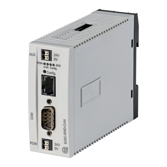
03/11 MN05013002Z-EN CANopen gateway EU5C-SWD-CAN Introduction The SmartWire-DT gateway EU5C-SWD-CAN creates a connection between the SmartWire-DT slaves and an over- riding CANopen master. Surface mounting Figure 28: Front view EU5C-SWD-CAN a 24-V power supply POW b Field bus interface c Diagnostics interface... -
Page 74: Engineering
DS301.4 on the field bus CANopen. Each SmartWire-DT slave is a module of its own. Up to 99 SmartWire-DT slaves can be operated via a PROFIBUS coupling unit. However, take heed of the maximum data volume that can be exchanged via CANopen. -
Page 75: Connection
Wire-DT slave electronics are performed via the terminals POW. The coupling unit contains an additional power feed module for the 15 V supply of the SmartWire-DT slaves with an amperage of 0.7 A. On the SmartWire-DT gateway connect the POW and AUX... - Page 76 3 A are connected, an additional feeder module EU5C- SWD-PF1 or EU5C-SWD-PF2 must be used. In the planning of the SmartWire-DT network you are also supported by the software program SWD-Assist, which automatically draws your attention to the use of any...
-
Page 77: Canopen Address Setting
03/11 MN05013002Z-EN Engineering CANopen address setting The coupling unit requires a unique address (node ID) in the CANopen network. This is set on the gateway via DIP switches (switches 3 - 8). Valid addresses are 1 - 32. CANopen connection Connection to the field bus is performed via a 9-pole D-SUB socket. -
Page 78: Programming System
Please follow the links provided there. Diagnostics interface The gateways have an online diagnostics interface with the following functions: • Update of the operating system of the SmartWire-DT gate- ways • Connection of the SWD-Assist for the online diagnostics of the SmartWire-DT network The EU4A-RJ45-CAB1 programming cable (serial SUB-D <->RJ45) or the EU4A-RJ45-USB-CAB1 USB cable... - Page 79 • Status indication of the inputs/outputs • Wiring test • Reading of the stored actual configuration • Reading the SmartWire-DT configuration • Comparison of the target and actual configuration • Display of cyclical and acyclical diagnostics messages Further details are described in the online Help of the SWD- Assist software.
- Page 80 03/11 MN05013002Z-EN...
-
Page 81: Installation Eu5C-Swd-Can
03/11 MN05013002Z-EN Installation EU5C-SWD-CAN Mounting Please proceed as follows to install the device: First of all set the CANopen address (node address). This is set on the gateway via DIP switches (switches 3-8). The DIP switches are located under a cover on the right-hand side of the gateway. - Page 82 If necessary, connect the 24 V DC voltage for the contactor coils to the terminals AUX. Danger! In safety-relevant applications the power supply providing power to the SmartWire-DT system must feature a PELV power feed module (protective extra low voltage). Caution! You must take safety precautions (emergency switching...
-
Page 83: Potential Conditions Between The Components
The entire SmartWire-DT system operates on a common supply voltage. Provide a common star point for the earth wiring. In this way the various slaves in the SmartWire-DT system will not be electrically isolated from one another. The field bus and the SmartWire-DT system are electrically isolated from one another. -
Page 84: Connection Smartwire-Dt
03/11 MN05013002Z-EN Installation EU5C-SWD-CAN Connection SmartWire-DT Connect the SmartWire-DT network. To do so use the SmartWire-DT cable SWD4-100LF8-24 and the relevant SWD4- 8MF2 spade connector or prefabricated cables of type SWD4-3F8-24-2S SWD4…LF… SWD4-8MF2 Figure 33: Connection SmartWire-DT Connection CANopen For connection to the CANopen cable you require a 9-pole SUB-D socket. -
Page 85: Emc-Conformant Wiring Of The Network
03/11 MN05013002Z-EN EMC-conformant wiring of the network EU5C-SWD-CAN 2 3 4 5 6 7 8 Node address Terminating resistor Figure 34: Activation of the terminating resistor EMC-conformant wiring of Undesired faults can occur on the field bus due to electro- the network magnetic interference. - Page 86 03/11 MN05013002Z-EN Installation EU5C-SWD-CAN for top-hat rail for mounting plate ZB4-102-KS1 ZB4-102-KS1 KLBü 3-8 SC FM 4/TS 35 (Weidmüller) (Weidmüller) Figure 35: Shielding of network cable...
-
Page 87: Eu5C-Swd-Can Commissioning
(actual configura- tion) each time the gateway is restarted. If the gateway ascertains in this process that a SmartWire-DT slave cannot be reached or a wrong slave type is determined, the Smart- Wire-DT network will not go into operation (to be precise this is dependent on the network configuration). -
Page 88: Switching On For Initial Startup, A Replacement Or A Changed Smartwire-Dt Configuration
Switching on for initial startup, a replacement or a changed SmartWire-DT configuration Prerequisite for reading the configuration: • All SmartWire-DT slaves are connected to the SmartWire- DT line. • The SmartWire-DT network is connected to the gateway. • Voltage POW is applied to the gateway and the power LED lights up. -
Page 89: Switching On When The Gateway Target Configuration Is Stored
The result of the check is displayed via the SmartWire-DT status LED on the gateway: Description Status SmartWire-... - Page 90 PROFIBUS master when the program is uploaded onto the controller. The CANopen master then transfers the configuration of the SmartWire-DT network to the gateway and tests it. (This only applies if you have checked Create SDOs for module list in the PLC configuration.) All status LEDs will be green if the configuration set matches the stored gateway configuration.
- Page 91 PLC system (= planned configura- tion) complies with the configuration actually available on the gateway. The result of this check is signalled on the gateway via the SmartWire-DT configuration LED. Table 9: Signals of the SmartWire-DT configuration LED...
- Page 92 03/11 MN05013002Z-EN...
-
Page 93: Programming The Eu5C-Swd-Can
CAN this is for example the file EU5C-SWD-CAN.eds. The name of the EDS file depends on the version. The relationship between supported SmartWire-DT slaves, SmartWire-DT gateways and EDS file is provided in the EU5C-SWD-CAN version table on page 135 in the Appendix. -
Page 94: Configuration And Parameterization With Easysoft-Codesys
03/11 MN05013002Z-EN Programming the EU5C-SWD-CAN Configuration and The connection of a SmartWire-DT network via the gateway parameterization with EU5C-SWD-CAN to the controller XC200 is described in this easySoft-CoDeSys section. Please check beforehand whether you have a current easySoft-CoDeSys version installed with the neces- sary EDS file. - Page 95 03/11 MN05013002Z-EN Configuration and parameterization with easySoft-CoDeSys Figure 36: Select the CAN master Mark the CAN master and via the menu option Insert -> Attach sub-element or the context menu open die selec- tion list of the CANopen slave modules. Select the gateway EU5C-SDW-CAN.
- Page 96 03/11 MN05013002Z-EN Programming the EU5C-SWD-CAN Figure 37: Selection of the gateways...
-
Page 97: Selecting The Smartwire-Dt Slave
Selecting the SmartWire-DT slave Change over to the CAN module selection tab. Now select here the SmartWire-DT slaves that you require for your SmartWire-DT network. Please heed of the correct sequence. The modules must be configured just as they will be arranged afterwards in your application. -
Page 98: Parameter Setting
These are the meanings of the individual tabs. “Basic parameters” tab Here you can define the I/O start addresses for the mapping of the SmartWire-DT slaves onto the inputs/outputs of the controller map. As standard the programming system creates a complete connection to the inputs/outputs up to now. - Page 99 03/11 MN05013002Z-EN Configuration and parameterization with easySoft-CoDeSys Guarding mechanisms Node guarding or heartbeat can be used to monitor commu- nication between the gateway and the CAN master. • Node guarding In node guarding the CAN master uses cyclical protocols to monitor the CAN slaves.
- Page 100 03/11 MN05013002Z-EN Programming the EU5C-SWD-CAN Figure 39: Setting the CAN parameters “Service data objects” tab In the Service data objects tab you can make parameter settings both for the SmartWire-DT network and for indi- vidual slaves.
-
Page 101: Parameters For The Smartwire-Dt Network
If not, no data interchange takes place with the CAN 0 = No) master. Data interchange also takes place, if the SmartWire-DT slaves are not identical to the CANopen configuration, but are compatible with each other. This is indicated by the Status LED on the device. - Page 102 To find the parameters more easily the name of the slave and the position of the SmartWire-DT slave in the SmartWire-DT network are always appended to the actual settings (0 = first slave, 1 = second slave etc.).
- Page 103 Parameters Value Meaning (default) Device presence The SmartWire-DT slave must be present at the start or in (0 = optional; operation. If it is not addressable, the entire SmartWire-DT 1 = mandatory) network is stopped. Note: This is only effective, if the parameter "All slaves optional"...
-
Page 104: Input/Output Addresses
03/11 MN05013002Z-EN Programming the EU5C-SWD-CAN Input/output addresses The selection of the SmartWire-DT slaves in the controller configurator automatically causes the input/output addresses of the slaves to be assigned. The assignment of the addresses to the individual SmartWire-DT slaves can be viewed in the controller configuration. -
Page 105: Diagnostics
03/11 MN05013002Z-EN Diagnostics Diagnostics The system SmartWire-DT provides you with a basic diag- nosis and extended diagnostic information via emergency telegrams. Cyclic diagnostic information This basic diagnostic information is coded in the normal I/O map of each SmartWire-DT slave. They provide information about whether the slave is participating in normal data inter- change (i.e. - Page 106 03/11 MN05013002Z-EN Programming the EU5C-SWD-CAN Example M22-SmartWire-DT-K11-LED-R function element with one byte input (switch position indicator and diagnostic informa- tion) Byte 0: Diagnostics data Input data SUBST PRSNT - DIAG Designation Meaning NC1 = Normally Closed 0: contact actuated 1: Contact not actuated...
- Page 107 If the SmartWire-DT slave diagnosis (diagnosis bit = bit 4 is set), details on this can be determined by evaluating the extended diagnostic utilities. In the case of the SmartWire-DT slave considered here the following detailed conditions could be determined.
-
Page 108: Pdo Communication
03/11 MN05013002Z-EN Programming the EU5C-SWD-CAN PDO communication A maximum of 16 reception PDOs and 16 transmission PDOs are supported. A maximum of 128 bytes are therefore avail- able in each communication direction for utility data inter- change. Only the four default RX PDOs and the four default TX PDOs are active in basic state (after a reset of the gateway). - Page 109 03/11 MN05013002Z-EN Diagnostics Structure of the emergency telegram Byte 0: bytes1 Byte 2 Bytes 3-7 Emcy error code Emcy error code Error tab Error code (extended diagnosis) Emergency error code Error code (hex) Meaning 00xx Error reset (no errors) 01xx general error 50xx Devices-hardware...
- Page 110 03/11 MN05013002Z-EN Programming the EU5C-SWD-CAN Table 11: Manufacturer-specific messages Diagnostic code Meaning used by 0x00 No diagnostic message active All devices that support the extended diagnosis 0x10 Contact in middle position 0x11 Contact short-circuit 0x13 Output overload I/O module If "Emcy-Error-Code" =0xFF00 is displayed, a 32-bit variable with error flags in accordance with Table 12 is stored in the manufacturer-specific area (byte 4 to 7) of the EMCY tele- gram.
- Page 111 CANopen: monitoring error (node guarding/heartbeat.) Info SWD: project configuration check Free Info SWD: extended diagnosis of a slave is pending. Info SWD: CFG setting of at least one SmartWire-DT slave changed. Free Free Error SWD: necessary SmartWire-DT slave missing. Warning SWD: optional SmartWire-DT slave missing.
- Page 112 SWD: short-circuit in the 15 V power supply of the Smart- Wire-DT bus Error SWD: internal error of the SmartWire-DT coordinator Info SWD: at least one SmartWire-DT slave is transmitting a basic diagnosis. Error SWD: no SmartWire-DT slave found. Info SWD: the use of compatible slaves is allowed.
-
Page 113: Object Directory
03/11 MN05013002Z-EN Object directory Object directory The object list of the SmartWire-DT CANopen gateway consists of static and dynamic entries. Static entries are available in any case, dynamic entries being generated depending on the attached slaves. Static entries CANopen-specific entries (0x1000 - 0x1FFF) - Page 114 03/11 MN05013002Z-EN Programming the EU5C-SWD-CAN Index Subindex Data Type Default value Consumer heartbeat time 0x1017 Producer heartbeat time 0x1018 Identity object 0x1027 0-100 U16,(Sub0 = U8) Module list (VendorID+DeviceID) (rw)* 0x1029 Error behavior object / communication error (rw) 0x1200 Server-SDO-Parameters 0x1400 –...
- Page 115 User-specific entries (0x2000-0x5FFF) The following memory locations are scheduled: Index areas Entries 0x2000 - 0x20FF Configuration settings of the SmartWire-DT master 0x2100 - 0x21FF Configuration settings of the SmartWire-DT slaves 0x2200 - 0x22FF Acyclic communication with SmartWire-DT slaves 0x2300 - 0x23FF...
- Page 116 Acyclic communication with slaves (r/w) Extended diagnostic messages from SmartWire-DT slaves 0x2300-0x23FF 0..10 1…5 bytes Extended diagnostics of the SmartWire-DT slaves (ro) Baud rate SmartWire-DT (0x2000) • Content SmartWire-DT baud rate – 4 = 125 kBaud (Default setting) – 5 = 250 kBaud •...
- Page 117 • Content This global entry defines how the SmartWire-DT network behaves, if no slave is found. – 0 = it is individually settable for each SmartWire-DT slave whether it will be treated as an “optional” or “necessary” slave (default setting).
- Page 118 Programming the EU5C-SWD-CAN Configuration comparison mandatory (0x2003) • Content Via this entry it can be defined whether the SmartWire-DT gateway is allowed to start without the performance of a comparison between the target configuration and the project configuration. – 1 = the SmartWire-DT gateway also starts up without comparison between the planned configuration and the target configuration.
-
Page 119: Dynamic Entries
Specification of the dynamic object list entries is performed depending on the target configuration. Input and output data of the individual SmartWire-DT slaves are mapped into the PDOs in the order of the SmartWire-DT network structure. “Input byte” entry All input bytes of the SmartWire-DT slaves are listed. - Page 120 SmartWire-DT slaves registered in the target configuration. Subindex = 1 (U16): module no: an entry (module ID) is generated with the order in which the SmartWire-DT slaves were recorded in the target configuration. This entry is formed from the stringing together of the vendor ID and device ID.
- Page 121 – Subindex = 0: the subindex 0 represents the number of SmartWire-DT slaves registered in the target configura- tion. – Subindex = 1 to the number of SmartWire-DT slaves – Byte 1 = current SmartWire-DT address of the addressed slave –...
- Page 122 – Subindex = 0: The subindex 0 represents the number of SmartWire-DT slaves registered in the target configuration. – Subindex = 1 to the number of SmartWire-DT slaves: Number and format of the input and output data made available to these slaves •...
- Page 123 Data are written to the Planned configuration. The writing may be performed only in “pre-operational” status. The slave must support the changed parameter values. At present this property is not supported by SmartWire-DT slaves. Acyclic slave access (0x2200-0x22FF) • Content...
- Page 124 (Index = 0x2300 + SmartWire-DT slave address). A maximum of five diagnostic messages are stored for an SmartWire-DT slave; the length of a diagnostic entry is one byte. – Subindex 0: the number of diagnostic messages avail- able for this SmartWire-DT slave (values 0 - 5) –...
- Page 125 – Subindex = 0: The subindex 0 returns the number of input bytes avail- able in the stored gateway target configuration. – Subindex = 1 up to the number of SmartWire-DT slaves: Access to the input bytes available in the target config- uration.
- Page 126 – Subindex = 0: The subindex 0 returns the number of output bytes available in the target configuration. – Subindex = 1 up to the number of SmartWire-DT slaves: access to the output bytes available in the target config- uration.
-
Page 127: Compatibility
Each time the gateway starts there is a check whether this configuration has been changed. If this is the case, the data exchange between gateway and SmartWire-DT slaves is not started. (In this comparison, the missing slaves are not included, what is important is whether the found slaves are identical.) -
Page 128: The Planned Configuration Is Available
If the parameter “Compatible devices allowed” is set to 0, a defective SmartWire-DT slave can only be replaced by a slave of the same type. However, of the parameter is set to 1, deviations are allowed. The... - Page 129 03/11 MN05013002Z-EN Compatibility Table 15: List of types that are compatible with one another Part no. Description Allowed replace- Allowed replace- ment type 1 ment type 2 RMQ function elements (front mount) M22-SWD-K11 Function element, M22-SWD-K22 2 pos. front M22-SWD-K22 Function element, 3 pos.
- Page 130 03/11 MN05013002Z-EN Programming the EU5C-SWD-CAN Part no. Description Allowed replace- Allowed replace- ment type 1 ment type 2 RMQ function elements (base mount) M22-SWD-KC11 Function element, M22-SWD-KC22 2 pos., base M22-SWD-KC22 Function element, 3 pos., base M22-SWD-LEDC-W Function element, M22-SWD-K11LEDC-W M22-SWD-K22LEDC- LED-W, base M22-SWD-K11LEDC-W...
- Page 131 03/11 MN05013002Z-EN Compatibility Part no. Description Allowed replace- Allowed replace- ment type 1 ment type 2 DILM/MSC function elements DIL-SWD-32-001 DIL/MSC DIL-SWD-32-002 DIL-SWD-32-002 DIL/MSC, Manual/ Auto PKE-SWD-32 I/O function elements EU5E-SWD-4DX Digital module, 4 inputs EU5E-SWD-8DX Digital module, 8 inputs EU5E-SWD-4D4D Digital module, 4 inputs,...
- Page 132 03/11 MN05013002Z-EN...
-
Page 133: Appendix
PROFIBUS. No DP master is detected (for example, on account of a wrong slave address) Extended DP diagnostics: orange The input data from SmartWire-DT slaves is invalid or the necessary slaves are missing. The gateway is in firmware update mode changes from contin- when the POW LED is off. - Page 134 03/11 MN05013002Z-EN Appendix CAN status LED Description CAN status LED Data exchange gateway via the CANopen to PLC CAN interface inactive Baud rate detection active on the CAN red strobe light CAN baud rate detected, orange waiting for a valid target configuration Communication error on the CAN bus red flashing (error warning level reached)
- Page 135 The current actual configuration complies with the green contin- gateway target configuration. uous light A necessary SmartWire-DT slave is missing or the flashing (red) gateway target configuration does not comply with the actual configuration Slave addressing is active (after power On or the down- flashing load of a planned configuration with empty modules).
-
Page 136: Version Table For Eu5C-Swd-Dp
(e.g. Siemens (e.g. Siemens STEP7) STEP7) STEP7) Moel4d13.gsx Moel4d14.gsx Moel4d14.gsx Intel-format: Intel-format: Intel-format: (e.g. Moeller): (e.g. Moeller): (e.g. Moeller): Moe4d13.gsd Moe4d14.gsd Moe4d14.gsd SmartWire-DT slave I/O modules EU5E-SWD-8DX EU5E-SWD-4D4D EU5E-SWD-4D2R EU5E-SWD-4DX EU5E-SWD-X8D EU5E-SWD-4AX EU5E-SWD-2A2A EU5E-SWD-4PT DIL-/PKE-modules DIL-SWD-32-001 DIL-SWD-32-001 PKE-SWD-32 Circuit-breakers NZM-XSWD-704 RMQ-modules... - Page 137 03/11 MN05013002Z-EN Meaning of the LED indicators operating operating operating 2), 3) system: V1.00 system: V1.10 system: V1.20 Hardware: 01 Hardware: 01 Hardware: 01 GSD file: GSD file: GSD file: Motorola format Motorola format Motorola format (e.g. Siemens (e.g. Siemens (e.g.
- Page 138 SWD-Assist (from version 1.10) in the Help menu. The necessary operating systems can be downloaded from the Internet or are provided on your PC in the folder Program Files\Common Files\Eaton\SWD-FW. GSD files can be downloaded from the Internet at: http://www.moeller.net/de/support/index.jsp...
-
Page 139: Version Table For Eu5C-Swd-Can
V1.00 system: V1.10 system: V1.20 Hardware: 01 Hardware 01 Hardware 01 eds file: eds file: eds file: EU5C-SWD- EU5C-SWD- EU5C-SWD- CAN.eds CAN_V110.eds CAN_V120.eds SmartWire-DT slave I/O modules EU5E-SWD-8DX EU5E-SWD-4D4D EU5E-SWD-4D2R EU5E-SWD-4DX EU5E-SWD-X8D EU5E-SWD-4AX EU5E-SWD-2A2A EU5E-SWD-4PT DIL-/PKE-modules DIL-SWD-32-001 DIL-SWD-32-001 PKE-SWD-32 Circuit-breaker... - Page 140 03/11 MN05013002Z-EN Appendix EU5C-SWD-CAN Operating Operating Operating system: V1.00 system: V1.10 system: V1.20 Hardware: 01 Hardware 01 Hardware 01 eds file: eds file: eds file: EU5C-SWD- EU5C-SWD- EU5C-SWD- CAN.eds CAN_V110.eds CAN_V120.eds M22-SWD-K11LED-R M22-SWD-K11LED-W M22-SWD-K22 M22-SWD-K22LED-B M22-SWD-K22LEDC-B M22-SWD-K22LEDC-G M22-SWD-K22LEDC-R M22-SWD-K22LEDC-W M22-SWD-K22LED-G M22-SWD-K22LED-R M22-SWD-K22LED-W M22-SWD-KC11...
- Page 141 Meaning of the LED indicators If your gateway is using operating system V1V1.0 and you wish to use SmartWire-DT slaves requiring operating system V1.0 (e.g. PKE-SWD-32), you can update the oper- ating system of the gateway. For this choose the Update operating system function in the Help menu of the SWD- Assist planning software (version from 1.10) .
-
Page 142: Technical Data
03/11 MN05013002Z-EN Appendix Technical data EU5C-SWD-DP EU5C-SWD-CAN General Standards IEC/EN 61131-2, EN 50178 Dimensions (W x H x D) 35 X 90 X 127 Weight 0.16 0.16 Mounting Top-hat rail IEC/EN 60715, 35 mm Mounting position Vertical Ambient mechanical conditions Protection type (IEC/EN 60529, EN50178, VBG 4) IP20 IP20... - Page 143 Contact discharge (Level 2) Electromagnetic fields (IEC/EN 61131-2:2008) 80 - 1000 MHz 1.4 - 2 GHz 2 - 2.7 GHz Radio interference suppression (SmartWire-DT) EN 55011 Class A EN 55011 Class A Burst (IEC/EN 61131-2:2008, Level 3) Supply cables CAN/DP bus cable...
- Page 144 Overload proof Inrush current and length 12.5 A/6 ms 12.5 A/6 ms Heat dissipation at 24 V DC Potential isolation between U 15 V SmartWire-DT supply voltage Bridging voltage dips Repeat rate Status display SmartWire-DT supply voltage Rated operational voltage 14.5 g 3 %...
- Page 145 0.2 - 1.5 (AWG 24 - 16) Flexible with ferrule 0.25 - 1.5 0.25 - 1.5 SmartWire-DT network Slave type SmartWire-DT master Number of SmartWire-DT slaves Baud rate 125, 250 125, 250 Address setting automatic automatic Status display SmartWire-DT master LED: green...
- Page 146 03/11 MN05013002Z-EN...
-
Page 147: Index
03/11 MN05013002Z-EN Index Acyclical data communication CoDeSys ............39 STEP 7 ............61 Baud rate ............73 Blade terminal SmartWire-DT -4-8MF2 ....19 Bus termination resistor ........20 CAN master select ............91 CAN status LED ...........86 CANopen .............74 Address ............77 Address setting ..........73 Connection ...........73 Gateway ............70... - Page 148 03/11 MN05013002Z-EN Index DP master select ............30 easySoft-CoDeSys ..........30 EDS file ............74, 89 EU5C-SWD-CAN_V110.eds ......135 EU5C-SWD-CAN.eds ........74 Version ............135 Emergency error codes ........105 Emergency telegrams ........104 EU5C-SWD-CAN ..........69 EU5C-SWD-DP ............9 Front view ............9 Feeder module ............12 Field bus communication .......26, 85 GSD file CoDeSys ............14 Versions .............132...
- Page 149 Delay between cyclic data exchange .....98 DevicePresence ..........99 Disable configuration check ......98 Q_Byte ............99 Parameterization easySoft-CoDeSys .........30 SIMATIC S7, STEP 7 ........44 SmartWire-DT slave I/O addresses ....58 Assignment ..........104 Communication ..........104 PROFIBUS-DP cable ..........20 Programming ............89 Protection against polarity reversal ....19, 79 Ribbon cable ............18 SDO communication ..........104...
- Page 150 03/11 MN05013002Z-EN Index DP parameters ..........34 General ............52 Parameter assignment ........54 User parameters ...........35 Tabs Basic parameters ..........34 basic parameters ..........94 CAN parameters ...........94 Service data objects ........96 Technical data ...........138 Terminating resistor ..........80 Terminations ............18 Version EU5C-SWD-CAN ........135 EU5C-SWD-DP ...........132 Watchdog control ..........34 Wiring EMC compliant ..........81...
Need help?
Do you have a question about the SmartWire-DT and is the answer not in the manual?
Questions and answers