Eaton EU5C-SWD-EIP-MODTCP Manual
Smartwire-dt gateway
Hide thumbs
Also See for EU5C-SWD-EIP-MODTCP:
- Application (21 pages) ,
- Instruction leaflet (3 pages) ,
- Instruction leaflet (2 pages)
Table of Contents
Advertisement
Quick Links
Advertisement
Table of Contents

Related Manuals for Eaton EU5C-SWD-EIP-MODTCP


Summary of Contents for Eaton EU5C-SWD-EIP-MODTCP
- Page 1 Manual 08/17 MN120003Z EN SmartWire-DT Gateway EU5C-SWD-EIP-MODTCP...
- Page 2 No part of this manual may be reproduced, stored in a retrieval system, or transmit- ted in any form or by any means, electronic, mechanical, photocopying, micro-film- ing, recording or otherwise, without the prior written permission of Eaton Industries GmbH, Bonn.
- Page 3 Danger! Dangerous electrical voltage! Before commencing the installation • Disconnect the power supply of the device. • Ensure a reliable electrical isolation of the low voltage for the 24 V supply. Only use power supply units complying • Ensure that devices cannot be accidentally retriggered with IEC 60 364-4-41 (VDE 0100 Part 410) or HD 384.4.41 S2.
-
Page 5: Table Of Contents
2.1.3 Resetting the Ethernet address ........... 17 Mounting Considerations ............. 18 2.2.1 Mounting the EU5C-SWD-EIP-MODTCP gateway on a top-hat rail 18 2.2.2 Screwing the EU5C-SWD-EIP-MODTCP gateway into place..19 Potential Relationship between the Components......19 Connecting the power supply ............20 Connect SmartWire-DT .............. - Page 6 SWD modules object 0x65 ............69 Modbus/TCP – SmartWire-DT implementation...... 72 Overview of Modbus registers ............ 74 SmartWire-DT input/output data ..........75 Device informations Gateway............76 Time monitoring and Modbus-TCP operating mode ....76 Acyclic data communications............78 SmartWire-DT Gateway EU5C-SWD-EIP-MODTCP 08/17 MN120003Z EN www.eaton.com...
- Page 7 General ambient conditions ............100 9.2.3 Power supply ................101 9.2.4 SmartWire-DT ................102 9.2.5 Field bus interface Ethernet/IP and Modbus-TCP ......103 9.2.6 Diagnostics interface..............103 Compatible SWD module types........... 104 Index.................... 107 SmartWire-DT Gateway EU5C-SWD-EIP-MODTCP 08/17 MN120003Z EN www.eaton.com...
- Page 8 SmartWire-DT Gateway EU5C-SWD-EIP-MODTCP 08/17 MN120003Z EN www.eaton.com...
-
Page 9: About This Manual
Publication date Page(s) Subject Modi- fied 01/13 „"Replacement during operation permis- sible" device parameter“ 12/16 5,6,73 Target group, Addressing modes for Modbus 08/17 92, 102 Baud rates added SmartWire-DT Gateway EU5C-SWD-EIP-MODTCP 08/17 MN120003Z EN www.eaton.com... -
Page 10: Target Group
We assume no liability for any injury or damages incurred. SmartWire-DT Gateway EU5C-SWD-EIP-MODTCP 08/17 MN120003Z EN www.eaton.eu... -
Page 11: Reading Conventions
Indicates useful tips. ▶ Indicates instructions to be followed. For greater clarity, the name of the current chapter and the name of the cur- rent section are shown at the top of each page. SmartWire-DT Gateway EU5C-SWD-EIP-MODTCP 08/17 MN120003Z EN www.eaton.com... - Page 12 0 About this Manual 0.4 Reading conventions SmartWire-DT Gateway EU5C-SWD-EIP-MODTCP 08/17 MN120003Z EN www.eaton.eu...
-
Page 13: Smartwire-Dt Gateway Eu5C-Swd-Eip-Modtcp
1.1 Proper use 1 SmartWire-DT Gateway EU5C-SWD-EIP-MODTCP 1.1 Proper use EU5C-SWD-EIP-MODTCP SmartWire-DT gateways are used to establish a connection between a SmartWire-DT line, together with its SmartWire-DT modules, and a higher-level controller. SmartWire-DT is not designed for transmitting safety-relevant signals and must not be used as a replacement for controllers such as burner, crane, and two-hand safety controllers. -
Page 14: Versions
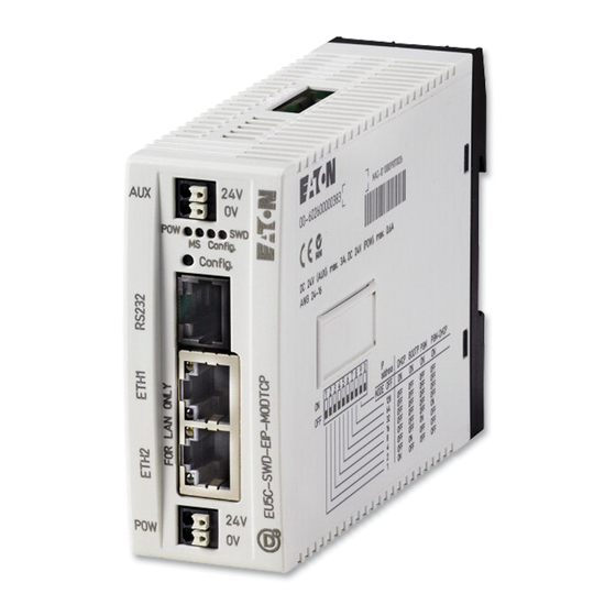
Power supply, 24 V DC POW b Fieldbus interface c Diagnostics interface d Configuration buttons e LED indicators: POW, MS, Config, SWD f Power supply, 24 V DC AUX g SmartWire-DT connection h Dip switch for address setting SmartWire-DT Gateway EU5C-SWD-EIP-MODTCP 08/17 MN120003Z EN www.eaton.com... -
Page 15: Important Data For Engineering
Ethernet switch. The ETH2 and ETH2 ports feature diagnostic LEDs used to indicate the corre- sponding link and data communications statuses. Finally, the unit will switch from 10 to 100 Mbit/s and vice versa automatically. SmartWire-DT Gateway EU5C-SWD-EIP-MODTCP 08/17 MN120003Z EN www.eaton.com... -
Page 16: Baud Rate
The gateway supports operation with the relevant field bus masters up to the following Baud rate: Fieldbus Maximum data baud rate in MBit/s EtherNet/IP 10/100 Modbus-TCP 10/100 The unit will adapt to the field bus master's Baud rate automatically. SmartWire-DT Gateway EU5C-SWD-EIP-MODTCP 08/17 MN120003Z EN www.eaton.com... -
Page 17: Installation
NOTICE Changes made to the dip switches' settings will take effect only after the power supply is turned off and back on again. 2.1.1 Default settings Ethernet address The EU5C-SWD-EIP-MODTCP gateway comes with the following default settings: IP address: 192.168.001.254 Subnet mask: 255.255.255.000... - Page 18 The DHCP server will deliver the IP address, the subnet mask, and the default gateway address. DHCP supports three IP address allocation mechanisms: • Automatic address allocation: The DHCP server assigns a permanent IP address to the client. SmartWire-DT Gateway EU5C-SWD-EIP-MODTCP 08/17 MN120003Z EN www.eaton.eu...
- Page 19 SWD-Assist program, the values entered are transferred to the gateway, where they are stored in non-volatile memory. Once the project is down- loaded, the corresponding addresses will take effect immediately. Figure 4: Adjusting Ethernet parameters with the SWD assist planning program SmartWire-DT Gateway EU5C-SWD-EIP-MODTCP 08/17 MN120003Z EN www.eaton.com...
- Page 20 The dip switches 1, 2, 3 are set to „OFF“. DIP Switch Description MODE PGM-DHCP: IP address received once via DHCP 1) X means that the position of the corresponding dip switch will be ignored. SmartWire-DT Gateway EU5C-SWD-EIP-MODTCP 08/17 MN120003Z EN www.eaton.eu...
-
Page 21: Resetting The Ethernet Address
Example: Address 18 2 3 4 5 6 7 8 Figure 5: Setting the field bus address on an EU5C-SWD-EIP-MODTCP gateway 2.1.3 Resetting the Ethernet address The gateway can be restored to its default settings at any time. To do this, set DIP switches 1 to 8, as well as the operating mode selector switch (DIP switch 9), to "OFF"... -
Page 22: Mounting Considerations
2.2 Mounting Considerations 2.2 Mounting Considerations Install the EU5C-SWD-EIP-MODTCP gateway in a control cabinet, a panel- board, or an enclosure in such a way that the power supply and terminal con- nections cannot be touched accidentally during operation. Snap the device onto an IEC/EN 60715 top-hat rail or fix it in place using fixing brackets. -
Page 23: Screwing The Eu5C-Swd-Eip-Modtcp Gateway Into Place
The device is mounted vertically on a top-hat rail in the same way. 2.2.2 Screwing the EU5C-SWD-EIP-MODTCP gateway into place For screw fixing, you will need two fixing brackets that can be used on the back of the EU5C-SWD-EIP-MODTCP gateway. Fixing brackets ZB4-101-GF1 are available as accessories. Figure 9:... -
Page 24: Connecting The Power Supply
The manual "SmartWire-DT The System", MN05006002Z, contains detailed calculation examples. 24 V DC Figure 11: Connection of power supply SmartWire-DT Gateway EU5C-SWD-EIP-MODTCP 08/17 MN120003Z EN www.eaton.eu... - Page 25 Cable protection for cable AWG 24 in accordance with UL 508 and CSA- 22.2 no. 14: • Miniature circuit-breaker 24 V DC rated operational current 2 A; trip type B or • Fuse 2 A SmartWire-DT Gateway EU5C-SWD-EIP-MODTCP 08/17 MN120003Z EN www.eaton.com...
-
Page 26: Connect Smartwire-Dt
DT external device plug (SWD4-8SF2-5) onto an 8-pin Smart- Wire-DT cable can be found in "SmartWire-DT The System", MN05006002Z, in the "Assembling external device plug SWD4- 8SF2-5" section. SWD4-…LF… SWD4-8MF Figure 12: Connection SmartWire-DT SmartWire-DT Gateway EU5C-SWD-EIP-MODTCP 08/17 MN120003Z EN www.eaton.eu... -
Page 27: Connect Field Bus
EtherNet/IP, Modbus-TCP ▶ Connect the EU5C-SWD-EIP-MODTCP gateway to the field bus. To do so use the integrated Ethernet switch, marked with ETH1, ETH2. In the case of EU5C-SWD-EIP-MODTCP, the operating system is updated using the field bus interface.→ Section “5.4 Updating the operating sys- tem”, page 54. -
Page 28: Connecting The Diagnostics Interface
2.7 Connecting the diagnostics interface 2.7 Connecting the diagnostics interface The EU5C-SWD-EIP-MODTCP SmartWire-DT gateway features a serial inter- face on the front. By using a programming cable, you can connect it to a computer and do the following with the corresponding software: •... -
Page 29: Wiring In Accordance With Emc Requirements
(cable, connection of the bus connectors, etc.), • Using shielding for top-hat rail for mounting plate ZB4-102-KS1 ZB4-102-KS1 KLBü 3-8 SC FM 4/TS 35 (Weidmüller) (Weidmüller) Figure 15: Field bus shielded by using a shield SmartWire-DT Gateway EU5C-SWD-EIP-MODTCP 08/17 MN120003Z EN www.eaton.com... - Page 30 2 Installation 2.8 Wiring in accordance with EMC requirements SmartWire-DT Gateway EU5C-SWD-EIP-MODTCP 08/17 MN120003Z EN www.eaton.eu...
-
Page 31: Commissioning
During this process, the gateway will determine whether there are any SWD modules that cannot be reached or whether a wrong type of mod- ule is plugged into the SWD line. SmartWire-DT's response to any detected SmartWire-DT Gateway EU5C-SWD-EIP-MODTCP 08/17 MN120003Z EN www.eaton.com... -
Page 32: Reading Of Target Configuration
The SmartWire-DT status LEDs of the SWD modules are on or are flash- ing. ▶ Press the configuration button on the gateway for at least two seconds. The SWD-LED on the gateway begins to flash orange. The SWD-LEDs on the SmartWire-DT modules also flash. SmartWire-DT Gateway EU5C-SWD-EIP-MODTCP 08/17 MN120003Z EN www.eaton.com... -
Page 33: Switching On When The Target Configuration Is Stored
Search for the field bus master in the PLC programming environment (target system) and configure the corresponding network settings Select the gateway as a field bus module. Configure the gateway's and the SWD modules' parameters in the PLC programming environment SmartWire-DT Gateway EU5C-SWD-EIP-MODTCP 08/17 MN120003Z EN www.eaton.com... -
Page 34: Creating Ethernetip/Modbus-Tcp Field Bus Communication
SWD configuration in the gateway once again. If the fieldbus protocol has been changed (EtherNet/IP or Mod- bus-TCP), the change will only take effect after the gateway is restarted. SmartWire-DT Gateway EU5C-SWD-EIP-MODTCP 08/17 MN120003Z EN www.eaton.com... -
Page 35: Ms-Led Status Display
If the other three gateway LEDs are permanently red, the operating system or the hardware is faulty. If they show continuous orange light, the gateway is in Firmware Update mode. This mode can be deactivated by switching on the power supply again. SmartWire-DT Gateway EU5C-SWD-EIP-MODTCP 08/17 MN120003Z EN www.eaton.com... - Page 36 3 Commissioning 3.2 Take the field bus into operation SmartWire-DT Gateway EU5C-SWD-EIP-MODTCP 08/17 MN120003Z EN www.eaton.com...
-
Page 37: Creating A Planned Smartwire-Dt Configuration In Swd-Assist
To create an SWD line for an EtherNet/IP field bus using the SWD-Assist planning program, you will need to follow the steps below: Select the EU5C-SWD-EIP-MODTCP gateway and configure its parame- ters Select the SmartWire-DT modules you want and configure their parame-... - Page 38 The maximum permitted length is 24 characters. The name can contain letters, numbers, and underscores (_). Umlauts are not permissi- ble, e.g., "ä," "ö." → The device name must not start with a number. SmartWire-DT Gateway EU5C-SWD-EIP-MODTCP 08/17 MN120003Z EN www.eaton.com...
-
Page 39: Select Swd Module
"Project" menu item and click on the "Plausibility check" option. Any errors–such as missing components–will be shown. For more information regarding how to set up an SWD line, please consult the online Help for SWD-Assist. SmartWire-DT Gateway EU5C-SWD-EIP-MODTCP 08/17 MN120003Z EN www.eaton.com... -
Page 40: Selecting A Communications Protocol
The protocol that should be used is selected either through the web interface or in the project with SWD-Assist. ▶ Open the "Device parameters" tab and select the field bus protocol you want using the "Mode" setting. SmartWire-DT Gateway EU5C-SWD-EIP-MODTCP 08/17 MN120003Z EN www.eaton.com... -
Page 41: Ethernet Parameters Tab
4.4 Ethernet parameters tab The EU5C-SWD-EIP-MODTCP gateway will communicate with the higher- level PLC via the Ethernet interface regardless of the field bus protocol you select. The gateway comes with the following default settings: IP address: 192.168.1.254... -
Page 42: Set Device Parameter Of The Gateway
To configure the SmartWire-DT coordinator's device parameters, use the set- tings in the "SWD settings" section. These settings will define the coordina- tor's behavior when the SmartWire-DT modules on the SWD line do not match the planned SmartWire-DT configuration in the gateway. SmartWire-DT Gateway EU5C-SWD-EIP-MODTCP 08/17 MN120003Z EN www.eaton.com... -
Page 43: Set The Device Parameters Of The Swd Modules
→ Section “Table 27: Device parameters of SWD modules”, page 93 Figure 23: Configuring the SmartWire-DT parameters for "PKEn2" in SWD-Assist 4.7 Setting specific device parameters for SmartWire-DT modules Certain SmartWire-DT modules make it possible to set additional device-spe- cific parameters. SmartWire-DT Gateway EU5C-SWD-EIP-MODTCP 08/17 MN120003Z EN www.eaton.com... -
Page 44: Storing The Planned Smartwire-Dt Configuration
Click on the "Configurations in device" button ▶ Under "Planned configuration," click on "PC=>Device" The planned SmartWire-DT configuration is now stored in the gateway. The Config LED will show a solid green light. SmartWire-DT Gateway EU5C-SWD-EIP-MODTCP 08/17 MN120003Z EN www.eaton.com... -
Page 45: Exporting The Smartwire-Dt Modules' I/O Data
Make sure that the right field bus protocol is selected. ▶ Open the "Project" menu and click on the "Export configuration" option. This will store all required information in a CSV or text file. SmartWire-DT Gateway EU5C-SWD-EIP-MODTCP 08/17 MN120003Z EN www.eaton.com... - Page 46 In the case of Modbus-TCP applications, the data can be exported in a text file format. Chapter → Chapter 5 "Commissioning the PLC programming environment“ describes how the CSV file for the EtherNet/IP communications protocol is used. SmartWire-DT Gateway EU5C-SWD-EIP-MODTCP 08/17 MN120003Z EN www.eaton.com...
-
Page 47: Commissioning The Plc Programming Environment
Eaton XC20x or XV20x PLC. 5.1 For Ethernet/IP, using RSLogix 5000 as an example In order to use the EU5C-SWD-EIP-MODTCP gateway in the RSLogix 5000 PLC programming environment, you will have to follow the steps below: Configure and set the parameters for the EtherNet/IP... - Page 48 Selecting the gateway as a "Generic Ethernet module" in RSLogix 5000 V19.01.00 ▶ In the "Select modules" dialog box, select the "Communications" group. ▶ Under "Communications," select the "Generic Ethernet module" device and confirm your selection by clicking on "OK." SmartWire-DT Gateway EU5C-SWD-EIP-MODTCP 08/17 MN120003Z EN www.eaton.com...
-
Page 49: Configuring The Gateway's Communication Parameters
▶ Use SWD-Assist to open your SmartWire-DT project file, e.g., "Exam- ple.swd". ▶ Select the EU5C-SWD-EIP-MODTCP gateway and open the "Device information" tab. ▶ Now copy the values for the inputs', outputs', and configuration data vol- umes found in SWD-Assist to the corresponding fields in the RSLogix 5000 parameter dialog box by hand →... -
Page 50: What The Swd-Assist Csv File Looks Like
The I/O address ("Specifier" column) is made up of: • The device name of the EtherNet/IP fieldbus module (the EU5C-SWD-EIP-MODTCP gateway); "EIPSWD" in this particular case • A code used to indicate whether the address is for an input (I) or an out- put (Q) •... -
Page 51: Importing The Smartwire-Dt Modules' I/O Data
PLC programming environment Once you are done with these steps, the programming system will have the I/O data and you will be able to use this data for your user program as usual. SmartWire-DT Gateway EU5C-SWD-EIP-MODTCP 08/17 MN120003Z EN www.eaton.com... - Page 52 5 Commissioning the PLC programming environment 5.1 For Ethernet/IP, using RSLogix 5000 as an example Figure 31: Tag list containing all of the SWD line's I/O data in the RSLogix 5000 V19.01.00 PLC programming environment SmartWire-DT Gateway EU5C-SWD-EIP-MODTCP 08/17 MN120003Z EN www.eaton.com...
-
Page 53: For Modbus/Tcp
A description of the specific input/output data If this information is used in order to generate input/output variables, the var- ious definition access methods of the PLC programming environment being used must be taken into account. SmartWire-DT Gateway EU5C-SWD-EIP-MODTCP 08/17 MN120003Z EN www.eaton.com... -
Page 54: Using Gateways With Elc/Modicon Controllers
5.2.3 Using gateways with Eaton controllers Eaton controllers (XC20x) and HMI displays with a PLC runtime functionality can be used as Modbus-TCP servers and clients. The library required for this purpose must be imported into the XSoft-CoDeSys programming software's library manager. -
Page 55: Web-Interface
5 Commissioning the PLC programming environment 5.3 Web-Interface 5.3 Web-Interface The web interface can be used to access the EU5C-SWD-EIP-MODTCP gate- way. The following functions are supported via the WEB interface: • Showing the gateway's device parameters • Showing the gateway's and SWD line's statuses •... -
Page 56: Updating The Operating System
To update the operating system on the gateway, follow the steps below: ▶ On the web interface, click on the "Browse..." button and select the "EU5C-SWD-EIP-MODTCP..." binary file from the folder where you saved ▶ Click on "Transfer to Device."... -
Page 57: Implemented Ethernet/Ip Objects
VSC object classes contain information concerning specific properties of indi- vidual SmartWire-DT modules, including, for example, diagnostic and param- eter information. Vendor-specific objects are described in → Section “6.2 Manufacturer-specific object classes”, page 63. SmartWire-DT Gateway EU5C-SWD-EIP-MODTCP 08/17 MN120003Z EN www.eaton.com... -
Page 58: Standard Cip Object Classes
10 (0x0A) Multiple_Service_ Packet Grouping of a self-defined number of attributes belonging to a class or instance 14 (0x0E) Get_Attribute_Single Delivers the contents of a single attribute 16 (0x10) Set_Attribute_Single Modifies a single attribute SmartWire-DT Gateway EU5C-SWD-EIP-MODTCP 08/17 MN120003Z EN www.eaton.com... -
Page 59: Identity Object 0X01
6 Implemented EtherNet/IP objects 6.1 Standard CIP object classes 6.1.1 Identity object 0x01 Identity object 0x01 delivers information via the EU5C-SWD-EIP-MODTCP SmartWire-DT gateway. This includes information regarding the device name, the device version, the serial number, and version information. Overview of functions... - Page 60 Class Instance Service name 1 (0x01) Get_Attribute_All Returns a pre-defined listing of this object's attributes 5 (0x05) Reset Starts the reset service for the device 14 (0x0E) Get_Attribute_Single Returns the specific attribute's content SmartWire-DT Gateway EU5C-SWD-EIP-MODTCP 08/17 MN120003Z EN www.eaton.com...
-
Page 61: Message Router Object 0X02
List of optional services 0x00 0A 6 (0x06) MAX CLASS IDENTIFIER UINT Highest number of the implemented 0x00 07 class attribute 7 (0x07) MAX INSTANCE ATTRIBUTE UINT Highest number of the implemented 0x00 02 instance attribute SmartWire-DT Gateway EU5C-SWD-EIP-MODTCP 08/17 MN120003Z EN www.eaton.com... - Page 62 Service name 1 (0x01) Get_Attribute_All Returns a pre-defined listing of this object's attributes 10 (0x0A) Multiple_Service_Packet Performs a set of services as an autonomous sequence. 14 (0x0E) Get_Attribute_Single Returns the specific attribute's content SmartWire-DT Gateway EU5C-SWD-EIP-MODTCP 08/17 MN120003Z EN www.eaton.com...
-
Page 63: Assembly Object 0X4
Highest number of the implemented 0x00 04 instance attribute Common Services Table 10: Common Services Service code Class Instance Instance Service name 14 (0x0E) Get_Attribute_Single Returns the specific attribute's content 16 (0x10) Set_Attribute_Single Modifies a single attribute. SmartWire-DT Gateway EU5C-SWD-EIP-MODTCP 08/17 MN120003Z EN www.eaton.com... - Page 64 This is equal to the size of the assembly object. The SmartWire-DT modules' input data is arranged continuously within the instance's data storage area. The beginning and the length of the individual input data for each module are also specified individually in SWD-Assist. SmartWire-DT Gateway EU5C-SWD-EIP-MODTCP 08/17 MN120003Z EN www.eaton.com...
-
Page 65: Example: I/O Data Mapping
EU5E-SWD-2A2A, analog module, 2 analog inputs, 2 analog outputs SWD-Assist shows the length of the instances of the assembly object for this configuration Assembly object instance Length Inputs 9 bytes Outputs 6 bytes SmartWire-DT Gateway EU5C-SWD-EIP-MODTCP 08/17 MN120003Z EN www.eaton.com... - Page 66 High Byte Gateway status Low Byte Gateway status → "Gateway status" is described in → Section “Table 7: Gateway device status”, page 56. The "SmartWire-DT Modules IP20", MN05006001Z describes the SmartWire-DT modules' input data. SmartWire-DT Gateway EU5C-SWD-EIP-MODTCP 08/17 MN120003Z EN www.eaton.com...
-
Page 67: Manufacturer-Specific Object Classes
The SmartWire-DT modules' data and settings 6.2.1 Gateway object 0x64 Gateway object 0x64 makes it possible to access the data corresponding to the EU5C-SWD-EIP-MODTCP gateway and the SmartWire-DT system. In addition, acyclic access to the SmartWire-DT modules' data is also available. Overview of functions... - Page 68 SmartWire-DT modules in the target configuration VENDOR USINT Manufacturer DEVICE USINT Device identification: 113 (0x71) INDEX USINT Object index for acyclic data 114 (0x72) DATA ARRAY of Data for reading / writing acyclic data USINT SmartWire-DT Gateway EU5C-SWD-EIP-MODTCP 08/17 MN120003Z EN www.eaton.com...
- Page 69 6 Implemented EtherNet/IP objects 6.2 Manufacturer-specific object classes Attribute number Attribute Name Get/Set Data type Description &Value 115 (0x73) LENGTH USINT Length of acyclic read/write data 1 – 120 116 (0x74) ERROR UINT Error Message SmartWire-DT Gateway EU5C-SWD-EIP-MODTCP 08/17 MN120003Z EN www.eaton.com...
-
Page 70: Gateway Status
Data will be transferred to the field bus master. The setting in the SWD modules → Section “Table 27: Device parameters of SWD modules”, page 93, will have no effect. 3 - 15 reserved SmartWire-DT Gateway EU5C-SWD-EIP-MODTCP 08/17 MN120003Z EN www.eaton.com... - Page 71 Communications monitoring time has elapsed (timeout) 0xFFF4 Com error Communication fault 0xFFF5 Not present SmartWire-DT module not available 0xFFF6 Permission denied Access prohibited 0xFFF7 Buffer size too small Buffer size (attribute 0x73) is too small for data SmartWire-DT Gateway EU5C-SWD-EIP-MODTCP 08/17 MN120003Z EN www.eaton.com...
- Page 72 Entry specifying which object should be written to ↓ SET attribute 115 (0x73h): Length of the byte array (1 - 120) ↓ SET attribute 114 (0x72h): Write the data ↓ GET attribute 116 (0x74h): Read the request's error status SmartWire-DT Gateway EU5C-SWD-EIP-MODTCP 08/17 MN120003Z EN www.eaton.com...
-
Page 73: Swd Modules Object 0X65
Manufacturer ID 103 (0x67) DEVICE ID USINT SmartWire-DT device classifica- tion 104 (0x68) ORDER NAME SHORT STRING Length and name of the Smart- Wire-DT module 105 (0x69) SERIAL NO. SHORT STRING Serial number SmartWire-DT Gateway EU5C-SWD-EIP-MODTCP 08/17 MN120003Z EN www.eaton.com... - Page 74 0: SmartWire-DT module not present (input data has a value of 0) 1: module present SUBST 0: Planned SmartWire-DT module present 1: Universal module present instead of planned SmartWire- DT module 4 - 15 RESERVED reserved SmartWire-DT Gateway EU5C-SWD-EIP-MODTCP 08/17 MN120003Z EN www.eaton.com...
- Page 75 M22 contact position undefined 0x11 M22 Contact to short-circuit 0x13 (Overload or short-circuit) 0x14 Internal error 0x15 Manual/Auto switch position undefined 0x16 S0 interface error 0x17 Value exceeds measuring range 0x18 Value falls below measurement range SmartWire-DT Gateway EU5C-SWD-EIP-MODTCP 08/17 MN120003Z EN www.eaton.com...
-
Page 76: Modbus/Tcp - Smartwire-Dt Implementation
Communications between Modbus modules are based on the client/server principle. The client, e.g., the PLC, uses function codes to transmit a request to the server, e.g., the EU5C-SWD-EIP-MODTCP gateway. The server responds to the request and returns the requested data to the client. If an error occurs during the communication request, e.g., because a request is... - Page 77 Used to write to a single word output register Write Multiple Registers Used to write to multiple word output registers Read/Write Multiple Registers Used to read from and write to multiple word regis- ters SmartWire-DT Gateway EU5C-SWD-EIP-MODTCP 08/17 MN120003Z EN www.eaton.com...
-
Page 78: Overview Of Modbus Registers
Request space for acyclic service objects → Section “7.5 Acyclic data communica- tions”, page 78 0x8080 - 0x80FF Results space for acyclic service objects → Section “7.5 Acyclic data communica- tions”, page 78 SmartWire-DT Gateway EU5C-SWD-EIP-MODTCP 08/17 MN120003Z EN www.eaton.com... -
Page 79: Smartwire-Dt Input/Output Data
Padding byte bytes3 Input word 2 input data instances of data type "byte" and 1 input data instance of data type "word" MODBUS register High byte Low byte 1 Byte Byte 2 Input word SmartWire-DT Gateway EU5C-SWD-EIP-MODTCP 08/17 MN120003Z EN www.eaton.com... -
Page 80: Device Informations Gateway
• The controller switches from "Run" to "Stop" • The Ethernet cable that is connected to the gateway is disconnected • No Modbus-TCP communications between the PLC and the gateway SmartWire-DT Gateway EU5C-SWD-EIP-MODTCP 08/17 MN120003Z EN www.eaton.com... - Page 81 0x1120 in a non-volatile manner. To do this, a value of "0x7361" is first written to register 0x113E. However, the data is not actually stored until command "0x7665" ("SAVE") is written to register SmartWire-DT Gateway EU5C-SWD-EIP-MODTCP 08/17 MN120003Z EN www.eaton.com...
-
Page 82: Acyclic Data Communications
0 (not a modular Modbus module) 0x8004 LENGTH USINT 0 - 120 Length of data to be read or written 0x8005 - 0x807F OPTIONAL DATA UINT 0 - 0xFFFF Object-specific data or error codes (Register 0 - 122) SmartWire-DT Gateway EU5C-SWD-EIP-MODTCP 08/17 MN120003Z EN www.eaton.com... - Page 83 It is found in bits 4 to 7 of the first input byte of the cyclic data of each SmartWire-DT module: Table 24: SmartWire-DT module status Diagnostic data SUBST PRSNT – DIAG – – – – SmartWire-DT Gateway EU5C-SWD-EIP-MODTCP 08/17 MN120003Z EN www.eaton.com...
- Page 84 1: The SmartWire-DT module is present and is exchanging data with the gateway (SmartWire-DT coordinator). SUBST 0: The planned SmartWire-DT module is present 1: An M22-NOP(C) universal module is present instead of the planned SmartWire-DT module SmartWire-DT Gateway EU5C-SWD-EIP-MODTCP 08/17 MN120003Z EN www.eaton.com...
-
Page 85: What You Need To Know About Smartwire-Dt
① ② ② ② ② ② ② ② ③ Figure 36: SWD coordinator with SWD line a SWD coordinator b SWD module c Bus termination SmartWire-DT Gateway EU5C-SWD-EIP-MODTCP 08/17 MN120003Z EN www.eaton.com... - Page 86 In this way, you will be able to retain all module addresses.A detailed descrip- tion on connecting the universal modules is provided in the "SmartWire-DT Modules IP20", MN05006001Z. SmartWire-DT Gateway EU5C-SWD-EIP-MODTCP 08/17 MN120003Z EN www.eaton.com...
- Page 87 15 V DC supply voltage for other SWD modules on the SWD line. 15 V 15 V ① ② Figure 37: Schematic layout of an SWD line with the EU5C-SWD-PF2 power feeder module a EU5C-SWD-EIP-MODTCP b EU5C-SWD-PF2 SmartWire-DT Gateway EU5C-SWD-EIP-MODTCP 08/17 MN120003Z EN www.eaton.com...
-
Page 88: Configurations
▶ Switch on the power supply. The SWD LED will show a red light, indicating that, as expected, the mod- ules on the SWD line do not match the target configuration stored on the device. SmartWire-DT Gateway EU5C-SWD-EIP-MODTCP 08/17 MN120003Z EN www.eaton.com... - Page 89 The device information will show the STOP device status. SWD status: The Config LED will show a green light. This indicates that the target config- STOP uration and the planned SmartWire-DT configuration match. The device can now run. SmartWire-DT Gateway EU5C-SWD-EIP-MODTCP 08/17 MN120003Z EN www.eaton.com...
-
Page 90: Swd Cycle Time
= Number of user data bytes = 21 SWD cycle time t [ms] 21 · 10 bit + 2 bit · 9 + 30 bit · 10 = 4.224 ms 125 kBit/s SmartWire-DT Gateway EU5C-SWD-EIP-MODTCP 08/17 MN120003Z EN www.eaton.com... - Page 91 When the baud rate doubles, the SWD cycle time is cut in half. In the exam- ple above, the SWD cycle time goes from 4,224 ms at 125 kbit/s to 2.112 ms at 250 kbit/s. SmartWire-DT Gateway EU5C-SWD-EIP-MODTCP 08/17 MN120003Z EN www.eaton.com...
-
Page 92: Cyclical Input And Output Data Of The Swd Modules
0 and 1. With cyclical input data of one byte, it contains information on switch position and diagnostic informa- tion. Byte 0: Diagnostic data Input data SUBST PRSNT – DIAG – – SmartWire-DT Gateway EU5C-SWD-EIP-MODTCP 08/17 MN120003Z EN www.eaton.com... - Page 93 Extended diagnostic services If a SWD module is signaling "Diagnose," i.e., if bit 4 of input byte 0 is set to 1, the corresponding details can be obtained by evaluating the extended diag- nostic services. SmartWire-DT Gateway EU5C-SWD-EIP-MODTCP 08/17 MN120003Z EN www.eaton.com...
- Page 94 Further information on extended diagnostics is provided in the Online Help of SWD assist. For more information on how to evaluate the extended diagnostic messages in the PLC programming environment, please refer to → Section “6.2 Manu- facturer-specific object classes”, page 63. SmartWire-DT Gateway EU5C-SWD-EIP-MODTCP 08/17 MN120003Z EN www.eaton.com...
-
Page 95: Swd Device Parameters
8 What you need to know about SmartWire-DT 8.5 SWD device parameters 8.5 SWD device parameters For EU5C-SWD-EIP-MODTCP all device parameters are adjustable via SWD assist. A "required module" is a module for which the "Required module" device parameter = "1" so that it is enabled. -
Page 96: Device Paramters Of The Swd Gateway
In addition, the "All devices are optional"parameter must be set to "1".Otherwise, the entire line will be disabled if communications with one or more SmartWire-DT modules are lost. SmartWire-DT Gateway EU5C-SWD-EIP-MODTCP 08/17 MN120003Z EN www.eaton.com... -
Page 97: Device Parameters Of Swd Modules
Can be replaced with 0=Setpoint value universal module The SWD module can not be replaced by a universal module M22-SWD-NOP(C). The SWD module can be replaced by a universal module M22-SWD-NOP(C). SmartWire-DT Gateway EU5C-SWD-EIP-MODTCP 08/17 MN120003Z EN www.eaton.com... -
Page 98: Application Cases For The Effective Use Of The Device Parameters
After this, the SWD coordi- nator checks whether the "Can be replaced with universal module" device parameter is enabled for this module. If it is, the SWD line will start running. SmartWire-DT Gateway EU5C-SWD-EIP-MODTCP 08/17 MN120003Z EN www.eaton.com... -
Page 99: Faults On The Swd Line
If this error occurs during ongoing operation, e.g., because a module responds too late or is faulty, the SWD line will resume operation as soon as the error is fixed. A restart is not necessary. SmartWire-DT Gateway EU5C-SWD-EIP-MODTCP 08/17 MN120003Z EN www.eaton.com... - Page 100 In that case read further in → Section “ "Compatible devices per- missible" is enabled”, page 94 and → Section “ "Can be replaced with uni- versal module" is enabled”, page 94. In any case, you will have to press the "Config" configuration button. SmartWire-DT Gateway EU5C-SWD-EIP-MODTCP 08/17 MN120003Z EN www.eaton.com...
-
Page 101: Leds On The Device
Changes from perma- The gateway is in firmware update mode nent orange to red when the POW LED is off. The firmware update mode can be left by switching on the supply voltage again. SmartWire-DT Gateway EU5C-SWD-EIP-MODTCP 08/17 MN120003Z EN www.eaton.com... -
Page 102: Swd Assist
The Online Help function provides a detailed description of how to use SWD- Assist. In order to open it, click on the "?" icon on the SWD-Assist menu bar or press the F1 key. SmartWire-DT Gateway EU5C-SWD-EIP-MODTCP 08/17 MN120003Z EN www.eaton.com... -
Page 103: Appendix
Dimensions a inch Space units (SU) width Weight 0.16 0.35 Mounting Considerations Top-hat rail IEC/EN 60715, 35 mm or screw fixing usingfixing brackets ZB4-101-GF1 (accessories). Mounting position Horizontal or vertical Figure 39: Dimensions EU5C-SWD-EIP-MODTCP SmartWire-DT Gateway EU5C-SWD-EIP-MODTCP 08/17 MN120003Z EN www.eaton.com... -
Page 104: Technical Data
EN 55011 Class A Burst (IEC/EN 61131-2:2008, Level 3) Supply cables Fieldbus cable SmartWire-DT cables Surge (IEC/EN 61131-2:2008, Level 1) Supply cables/Fieldbus cable supply cable: 0.5, bus cable: 1 Radiated RFI (IEC/EN 61131-2:2008, Level 3) SmartWire-DT Gateway EU5C-SWD-EIP-MODTCP 08/17 MN120003Z EN www.eaton.com... -
Page 105: Power Supply
Bridging voltage dips Repeat rate Status display POW-LED plain color: orange 1) When the total power consumption > I an EU5C-SWD-PF1 or EU5C-SWD-PF2 power feeder module has to be used. SmartWire-DT Gateway EU5C-SWD-EIP-MODTCP 08/17 MN120003Z EN www.eaton.com... -
Page 106: Smartwire-Dt
Bus termination resistor SWD line integrated in the device: the end of the SWD line must be terminated with SWD-RC8-10 1) When the total power consumption > I an EU5C-SWD-PF2 power feeder module has to be used. SmartWire-DT Gateway EU5C-SWD-EIP-MODTCP 08/17 MN120003Z EN www.eaton.com... -
Page 107: Field Bus Interface Ethernet/Ip And Modbus-Tcp
POW / AUX from serial interface from SmartWire-DT 9.2.6 Diagnostics interface EU5C-SWD-EIP-MODTCP Diagnostics interface Part no. RS232 Terminal types RJ45 Potential isolation from power supply POW / AUX from SmartWire-DT from fieldbus interface SmartWire-DT Gateway EU5C-SWD-EIP-MODTCP 08/17 MN120003Z EN www.eaton.com... -
Page 108: Compatible Swd Module Types
M22-SWD-K22LED-G Function element, 3 pos., LED G, front M22-SWD-LED-B Function element, LED B front M22-SWD-K11LED-B M22-SWD-K22LED-B M22-SWD-K11LED-B Function element, 2 pos., LED B, front M22-SWD-K22LED-B M22-SWD-K22LED-B Function element, 3 pos., LED B, front SmartWire-DT Gateway EU5C-SWD-EIP-MODTCP 08/17 MN120003Z EN www.eaton.com... - Page 109 Digital module, 4 inputs, 2 outputs EU5E-SWD-X8D Digital module, 8 outputs EU5E-SWD-4AX Analog module, 4 inputs EU5E-SWD-2A2A Analog module 2 inputs, 2 outputs EU5E-SWD-4PT Analog module, 4 temperature inputs EU5E-SWD-4PT-2 Analog module, 4 temperature inputs SmartWire-DT Gateway EU5C-SWD-EIP-MODTCP 08/17 MN120003Z EN www.eaton.com...
- Page 110 9 Appendix 9.3 Compatible SWD module types SmartWire-DT Gateway EU5C-SWD-EIP-MODTCP 08/17 MN120003Z EN www.eaton.com...
-
Page 111: Index
..... . . 84 Putting the SmartWire-DT into operation ..27 SmartWire-DT Gateway EU5C-SWD-EIP-MODTCP 08/17 MN120003Z EN www.eaton.eu... - Page 112 . 25 Wrong module ......96 SmartWire-DT Gateway EU5C-SWD-EIP-MODTCP 08/17 MN120003Z EN www.eaton.eu...
- Page 113 Eaton is dedicated to ensuring that reliable, efficient and safe power is Eaton addresses worldwide: available when it’s needed most. With unparalleled knowledge of www.eaton.com./address electrical power management across industries, experts at Eaton deliver customized, integrated solutions to solve our customers’ most critical challenges.
Need help?
Do you have a question about the EU5C-SWD-EIP-MODTCP and is the answer not in the manual?
Questions and answers