Table of Contents
Advertisement
Quick Links
Advertisement
Table of Contents

Related Manuals for Eaton XNE-GWBR-2ETH-MB


Summary of Contents for Eaton XNE-GWBR-2ETH-MB
- Page 1 User Manual XI/ON 10/2011 MN05002008Z-EN XNE-GWBR-2ETH-MB Gateway...
- Page 2 All rights reserved, also for the translation. None of this document may be reproduced or processed, duplicated or distributed by electronic systems in any form (print, photocopy, microfilm or any other process) without the written permission of Eaton Automa- tion AG, St. Gallen.
- Page 3 (for example, by means of separate limit switches, mechanical inter- locks etc.). • The electrical installation must be carried out in accordance with the relevant regulations (e. g. with regard to cable cross sections, fuses, PE). XI/ON: XNE-GWBR-2ETH-MB 10/2011 MN05002008Z-EN www.eaton.com...
- Page 4 • All work relating to transport, installation, commissioning and maintenance must only be carried out by qualified personnel. (IEC/HD 60364 (DIN VDE 0100) and national work safety regulations). • All shrouds and doors must be kept closed during operation. XI/ON: XNE-GWBR-2ETH-MB 10/2011 MN05002008Z-EN www.eaton.com...
-
Page 5: Table Of Contents
Service interface connection (mini USB female connector) ....... Address setting ....................4.5.1 Default-settings for the gateway................ 4.5.2 Function of the DIP-switches ................4.5.3 Address-setting via DIP-switches 2 to 2 ............4.5.4 Address setting via DHCP-mode................ 4.5.5 Address setting via BootP-mode................ XI/ON: XNE-GWBR-2ETH-MB 10/2011 MN05002008Z-EN www.eaton.com... - Page 6 Reading-out the process image length (inputs)..........122 6.3.5 Reading-out the packet process data (inputs) ............ 123 6.3.6 Evaluation of the packed process data (inputs) ..........124 6.3.7 Setting of outputs....................127 Parameterization of modules................129 XI/ON: XNE-GWBR-2ETH-MB 10/2011 MN05002008Z-EN www.eaton.com...
- Page 7 9.1.1 Counter module XN-1CNT-24VDC..............157 9.1.2 Counter module XNE-2CNT-2PWM ..............170 9.1.3 RS×××-module....................179 9.1.4 SSI-module ......................183 9.1.5 SWIRE-module ....................189 Ident codes of the XI/ON modules..............192 Glossary ......................194 Index ........................199 XI/ON: XNE-GWBR-2ETH-MB 10/2011 MN05002008Z-EN www.eaton.com...
- Page 8 Table of contents XI/ON: XNE-GWBR-2ETH-MB 10/2011 MN05002008Z-EN www.eaton.com...
-
Page 9: About This Manual
XN-1RS485/422 • MN05002015Z User Manual XI/ON XN-1SSI • MN05002016Z User Manual XI/ON XNE-1SWIRE Furthermore, the manual mentioned above contains a short description of the project planning and diagnostics software for Eaton I/O-systems, the software I/O-ASSISTANT. XI/ON: XNE-GWBR-2ETH-MB 10/2011 MN05002008Z-EN www.eaton.com... -
Page 10: Description Of Symbols Used
This sign can be found next to all general notes that supply important information about one or more operating steps. These specific notes are intended to make operation easier and avoid unnecessary work due to incorrect operation. XI/ON: XNE-GWBR-2ETH-MB 10/2011 MN05002008Z-EN www.eaton.com... -
Page 11: Overview
Please read this section carefully. Safety aspects cannot be left to chance when dealing with electrical equipment. This manual includes all information necessary for the prescribed use of the gateway XNE-GWBR-2ETH-MB. It has been specially conceived for personnel with the necessary qual- ifications. 1.3.1... - Page 12 1 About this manual 1.3 Overview XI/ON: XNE-GWBR-2ETH-MB 10/2011 MN05002008Z-EN www.eaton.com...
-
Page 13: Xi/On Philosophy
34 mm/ 1.34 inch, XN standard slice 12.6 mm / 0.49 inch, XNE ECO slice 13 mm / 0.51 inch and block 100.8 mm / 3.97 inch) and their low overall height favor the installation of this system in confined spaces. XI/ON: XNE-GWBR-2ETH-MB 10/2011 MN05002008Z-EN www.eaton.com... -
Page 14: Easy To Handle
• The gateway and the electronics modules are snapped onto a mounting rail. • The electronics modules of the ECO line are designed as terminal blocks. The wiring is secured by "push-in" spring-type terminal. XI/ON: XNE-GWBR-2ETH-MB 10/2011 MN05002008Z-EN www.eaton.com... -
Page 15: Xi/On Components
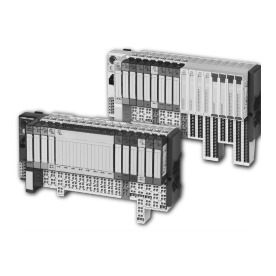
• Automatic bit rate detection for PROFIBUS-DP and CANopen • Setting of field bus address and bus terminating resistor (PROFIBUS-DP, CANopen) via DIP-switches • Service interface for commissioning with I/O-ASSISTANT Figure 1: Gateway XNE-GWBR- 2ETH-MB XI/ON: XNE-GWBR-2ETH-MB 10/2011 MN05002008Z-EN www.eaton.com... - Page 16 XN-GW gateways. Note The gateway types XN-GW-… need an additional power supply module (bus refresh- ing module) which feeds the gateway an the connected I/O modules. Figure 2: Gateway example: XN-GWBR- PBDP XI/ON: XNE-GWBR-2ETH-MB 10/2011 MN05002008Z-EN www.eaton.com...
-
Page 17: Power Supply Modules
Figure 4: XN standard electronics module in slice design (left) and in block design (reght) XI/ON: XNE-GWBR-2ETH-MB 10/2011 MN05002008Z-EN www.eaton.com... - Page 18 – XN standard electronics modules with base modules with tension clamp connection technology, – XN standard gateways with an integrated power supply unit (XN-GWBR-…) and – XNE ECO gateways • Simple assembly reduces error sources Figure 5: XNE ECO elec- tronics module XI/ON: XNE-GWBR-2ETH-MB 10/2011 MN05002008Z-EN www.eaton.com...
-
Page 19: Base Modules
3, 4 or 6 connection levels in tension clamp or in screw connection technology. Figure 6: Base module with tension clamp connec- tion Figure 7: Base module with screw con- nection Figure 8: Base module in block design XI/ON: XNE-GWBR-2ETH-MB 10/2011 MN05002008Z-EN www.eaton.com... -
Page 20: End Plate
A second end bracket to the left of the gateway is necessary, as well as the one mounted into the end plate to secure the XI/ON station. Figure 10: End bracket Note The scope of delivery of each gateway contains an end plate and two end brackets. XI/ON: XNE-GWBR-2ETH-MB 10/2011 MN05002008Z-EN www.eaton.com... -
Page 21: Jumpers
Figure 11: Jumpers 2.2.8 Marking material • Labels: for labeling electronics modules. • Markers: for colored identification of connection levels of base modules and XN electronics modules. Figure 12: Marking material XI/ON: XNE-GWBR-2ETH-MB 10/2011 MN05002008Z-EN www.eaton.com... -
Page 22: Shield Connection For Gateways
Shield connection, 2-pole for analog modules The 2-pole shield connection can be used to connect signal-cable shielding to the base modules of analog input and output modules. Figure 14: Shield connec- tion, 2-pole for analog modules XI/ON: XNE-GWBR-2ETH-MB 10/2011 MN05002008Z-EN www.eaton.com... -
Page 23: Ethernet
The IP address is a 4-byte-value which contains the address of the network to which the node is connected as well as the host address in the network. The IP address of the gateway XNE-GWBR-2ETH-MB is predefined as follows: IP address: 192.168.1.×××... -
Page 24: Network Classes
The Transmission Control Protocol (TCP) is a connection-oriented transport protocol and is based on the Internet Protocol. A safe and error-free data transport can be guaranteed by means of certain error diagnostic mechanisms as for example acknowledgement and time monitoring of telegrams. XI/ON: XNE-GWBR-2ETH-MB 10/2011 MN05002008Z-EN www.eaton.com... -
Page 25: Checking The Communication Via "Ping-Signals
For that purpose, please enter the command "ping" and the IP address of the network node to be checked. If the node answers the ping-signal, it is ready for communication and takes part in the data transfer. Figure 16: ping-signal XI/ON: XNE-GWBR-2ETH-MB 10/2011 MN05002008Z-EN www.eaton.com... -
Page 26: Arp (Address Resolution Protocol)
Figure 17: Determination of the MAC-ID of a XI/ON mo- dule via ARP 3.1.7 Transmission media For a communication via Ethernet, different transmission media can be used (see Chapter 8.1.4, Page 150). XI/ON: XNE-GWBR-2ETH-MB 10/2011 MN05002008Z-EN www.eaton.com... -
Page 27: Technical Features
4.1 General Technical Features General This chapter contains the general technical description of the gateway XNE-GWBR-2ETH-MB for Ethernet. The following technical features are independent of the implemented protocol. The chapter describes: the technical data, the connection possibilities, the addressing of the gateway etc. -
Page 28: Technical Data
DIP-switch for operation mode DIP-switch for configuration storage LED for the Modbus-commu- nication EtherNet- switch with EtherNet-LEDs Push-in ten- sion clamps for field supply Push-in ten- sion clamps for system supply XI/ON: XNE-GWBR-2ETH-MB 10/2011 MN05002008Z-EN www.eaton.com... -
Page 29: Block Diagram
(at maximum station extension 600 mA max. → see Chapter 7.2, Page 139) (supply to the moudle bus participants) 400 mA Insulation voltage (U to U 500 V to field bus / U to FE) XI/ON: XNE-GWBR-2ETH-MB 10/2011 MN05002008Z-EN www.eaton.com... - Page 30 0.075 mm / 0.003 inch, 1g 57 to 150 Hz, constant acceleration 1 g Mode of vibration Frequency sweeps with a change in speed of 1 Octave/min Period of oscillation 20 frequency sweeps per axis of coordinate XI/ON: XNE-GWBR-2ETH-MB 10/2011 MN05002008Z-EN www.eaton.com...
- Page 31 Note For testing high energie surge (according to IEC/EN 61000-4-5 and product standard IEC/EN 61131-2) a cable lenght of digital and analogue I/O ports is specified with < 30 m. XI/ON: XNE-GWBR-2ETH-MB 10/2011 MN05002008Z-EN www.eaton.com...
-
Page 32: Approvals And Tests
DIN 46228-1 (ferrules crimped gas-tight) "f” with ferrules with plastic collar 0.25 to 0.75 mm / 0.0004 to 0.0012 inch according to DIN 46228-1 (ferrules crimped gas-tight) Test finger according to IEC/EN 60947-1 XI/ON: XNE-GWBR-2ETH-MB 10/2011 MN05002008Z-EN www.eaton.com... -
Page 33: Connection Options At The Gateway
Figure 20: Connection level at the gateway 4.4.1 Power supply The XNE-GWBR-2ETH-MB provides an integrated power supply unit and push-in tension clamps for: • field supply (U , GND • system supply (U , GND 4.4.2 Field bus connection via Ethernet-switch The XI/ON-ECO-gateways for Ethernet provide an integrated RJ45-Ethernet-switch. -
Page 34: Service Interface Connection (Mini Usb Female Connector)
The service interface is designed as a 5 pole mini-USB-connection. In order to connect the gateway’s service-interface to the PC, a commercial cable with mini USB connector is necessary. Figure 22: Mini-USB- female connec- tor at the gate- XI/ON: XNE-GWBR-2ETH-MB 10/2011 MN05002008Z-EN www.eaton.com... -
Page 35: Address Setting
After every change of the address-mode, a voltage reset must be carried out. 4.5.2 Function of the DIP-switches The DIP-switches for address setting, operation mode setting and for the storage of the station configuration are located under the gateway’s upper label. Figure 23: DIP-switches at the gateway XI/ON: XNE-GWBR-2ETH-MB 10/2011 MN05002008Z-EN www.eaton.com... -
Page 36: Address-Setting Via Dip-Switches
Setting the „Default-settings for the gateway”. 1-254 „Address-setting via DIP-switches 20 to 27” (Setting the last byte of the gateway’s IP-address) Gateway-„Address setting via DHCP-mode” Gateway-„Address setting via BootP-mode” Gateway-„Address setting via PGM-mode” invalid XI/ON: XNE-GWBR-2ETH-MB 10/2011 MN05002008Z-EN www.eaton.com... - Page 37 EEPROM. Thus, they will get lost in case of a subsequent address-assignment via a BootP, DHCP or PGM. Attention After changing the position of the DIP-switches, a voltage reset must be carried out to store the new address. XI/ON: XNE-GWBR-2ETH-MB 10/2011 MN05002008Z-EN www.eaton.com...
- Page 38 4 Technical Features 4.5 Address setting LED-behavior During the module’s start-up, the "MS" LED shortly becomes constant red. After the successful start-up, the LED begins to flash green and the station is then ready for communi- cation. XI/ON: XNE-GWBR-2ETH-MB 10/2011 MN05002008Z-EN www.eaton.com...
-
Page 39: Address Setting Via Dhcp-Mode
During it’s start-up, the module waits for the address setting via DHCP-/BootP-server. This is indicated by the red flashing "MS" LED. The LED begins to flash green, as soon as the address setting via the server is completed. The station is ready for communication. XI/ON: XNE-GWBR-2ETH-MB 10/2011 MN05002008Z-EN www.eaton.com... -
Page 40: Address Setting Via Bootp-Mode
During it’s start-up, the module waits for the address setting via DHCP-/BootP-server. This is indicated by the red flashing "MS" LED. The LED begins to flash green, as soon as the address setting via the server is completed. The station is ready for communication. XI/ON: XNE-GWBR-2ETH-MB 10/2011 MN05002008Z-EN www.eaton.com... -
Page 41: Address Setting Via Pgm-Mode
During it’s start-up, the module waits for the address setting via DHCP-/BootP-server. This is indicated by the red flashing "MS" LED. The LED begins to flash green, as soon as the address setting via the server is completed. The station is ready for communication. XI/ON: XNE-GWBR-2ETH-MB 10/2011 MN05002008Z-EN www.eaton.com... -
Page 42: Address Setting Via The Software "I/O-Assistant
Address Tool. Note The access of the I/O-ASSISTANT to the gateway is only possible if the gateway is operated in PGM-mode (see also Chapter 4.5.6 Address setting via PGM-mode, Page 41). Figure 29: Opening the Address-Tool XI/ON: XNE-GWBR-2ETH-MB 10/2011 MN05002008Z-EN www.eaton.com... - Page 43 Please observe that, if the system integrated Windows-firewall is activated, difficul- ties may occur during the communication between the gateway and the Address- tool. The firewall may possibly inhibit the access of the tool on Ethernet. XI/ON: XNE-GWBR-2ETH-MB 10/2011 MN05002008Z-EN www.eaton.com...
-
Page 44: Storing The Station Configuration
→ storage process terminated successfully, if the LEDs IOs and GW are constant green. Note If the DIP-switch is not set back, the gateway will continiously restart the storage process. Only setting the switch back from ON to OFF will terminate this process. XI/ON: XNE-GWBR-2ETH-MB 10/2011 MN05002008Z-EN www.eaton.com... -
Page 45: Status Indicators/Diagnostic Messages Gateway
– hardware error in gateway Red/green WINK-Command active The software I/O-ASSISTANT is flashing, executing a WINK command on 4 Hz the device. This command is executed in order to find out which network node is accessed. XI/ON: XNE-GWBR-2ETH-MB 10/2011 MN05002008Z-EN www.eaton.com... - Page 46 Green Displays the logical connection to – a Master (1. Modbus TCP- connection) Green Gateway is ready for operation – flashing Gateway indicates error – DHCP/BootP search of settings, – flashing wait for address setting XI/ON: XNE-GWBR-2ETH-MB 10/2011 MN05002008Z-EN www.eaton.com...
- Page 47 Status Meaning Remedy LED-displays ETH1, No Ethernet link – Check the Ethernet-connection. ETH2 Green Link with 10/100 Mbps – Green Ethernet Traffic – flashing Yellow 100 Mbps (if no LED lits yellow: – 10 Mbps) XI/ON: XNE-GWBR-2ETH-MB 10/2011 MN05002008Z-EN www.eaton.com...
- Page 48 4 Technical Features 4.7 Status indicators/diagnostic messages gateway XI/ON: XNE-GWBR-2ETH-MB 10/2011 MN05002008Z-EN www.eaton.com...
-
Page 49: Implementation Of Modbus Tcp
Protocol Specification V1.1 of Modbus-IDA): Figure 32: Modbus Application Layer Schematic representation of the Modbus Communication Stack Modbus TCP others Modbus plus Master/Slave Client/Server Rsxxx Ethernet Physical layer Physical layer Physical layer Physical layer XI/ON: XNE-GWBR-2ETH-MB 10/2011 MN05002008Z-EN www.eaton.com... -
Page 50: Protocol Description
If no error occurs related to the Modbus function requested in a properly received Modbus ADU the data field of a response from a server to a client contains the data requested. Figure 34: Modbus data transmission (acc. to Mod- bus-IDA) XI/ON: XNE-GWBR-2ETH-MB 10/2011 MN05002008Z-EN www.eaton.com... -
Page 51: Data Model
Access to these data is done via defined access-addresses (see Chapter 5.3 Modbus regis- ters, Page 54). The example below shows the data structure in a device with digital and analog in- and outputs. XI/ON: XNE-GWBR-2ETH-MB 10/2011 MN05002008Z-EN www.eaton.com... - Page 52 XI/ON devices have only one data block, whose data can be accessed via different Modbus functions. The access can be carried out either via registers (16-bit-access) or, for some of them, via single-bit-access. Figure 36: Picture of the data memory of the XI/ON gate- ways XI/ON: XNE-GWBR-2ETH-MB 10/2011 MN05002008Z-EN www.eaton.com...
-
Page 53: Implemented Modbus Functions
Write Single Register Serves for writing single output registers Write Multiple Coils Serves for writing multiple output bits Write Multiple Registers Serves for writing multiple output registers Read/Write Multiple Registers Serves for reading and writing multiple registers XI/ON: XNE-GWBR-2ETH-MB 10/2011 MN05002008Z-EN www.eaton.com... -
Page 54: Modbus Registers
5 Implementation of Modbus TCP 5.3 Modbus registers Modbus registers Note The Table 11:, Mapping of XNE-GWBR-2ETH-MB Modbus registers (holding regis- ters), Page 56 shows the register mapping for the different Modbus addressing methods. Table 10: Address (hex.) Access Description... - Page 55 (128 × 64 Byte, but: maximum module number for XI/ON = 32 modules per station) 0×B000 to 0×BFFF parameters (128 × 64 Byte, but: maximum module number for XI/ON = 32 modules per station) XI/ON: XNE-GWBR-2ETH-MB 10/2011 MN05002008Z-EN www.eaton.com...
- Page 56 0x2080 to 8320 to 48321 to 408321 to 0x20FF 8447 48448 408448 system voltage U [mV] 0x2400 9216 49217 409217 load voltage U [mV] 0x2401 9217 49218 409218 load current I 0x2405 9221 49222 409222 XI/ON: XNE-GWBR-2ETH-MB 10/2011 MN05002008Z-EN www.eaton.com...
- Page 57 32832 432833 Slot 32 0×93E0 33760 433761 diagnostics (32 × 64 bytes) 0xA000 to 0xA400 Slot 1 0×A000 40960 440961 Slot 2 0×A020 40992 440993 Slot 3 0×A040 41034 441035 Slot 32 0×A3E0 41952 441953 XI/ON: XNE-GWBR-2ETH-MB 10/2011 MN05002008Z-EN www.eaton.com...
- Page 58 5.3 Modbus registers Description Decimal 5-Digit Modicon parameters (32 × 64 bytes) 0xB000 to 0xB400 Slot 1 0×B000 45056 445057 Slot 2 0×B020 45088 445089 Slot 3 0×B040 45120 445121 Slot 32 0×B3E0 46048 446049 XI/ON: XNE-GWBR-2ETH-MB 10/2011 MN05002008Z-EN www.eaton.com...
-
Page 59: Structure Of The Packed In-/ Output Process Data
Note An example in Chapter 6.3 Communication examples: Modbus TCP, Page 116. de- scribes the data mapping. Additionally, the software I/O-ASSISTANT offers the pos- sibility to create a mapping table for every station. XI/ON: XNE-GWBR-2ETH-MB 10/2011 MN05002008Z-EN www.eaton.com... -
Page 60: Packed Input-Process Data
Note Independent of the I/O-configuration, an access to all 512 registers is always possi- ble. Registers that are not used send "0" answering a read access, write accesses are ignored. XI/ON: XNE-GWBR-2ETH-MB 10/2011 MN05002008Z-EN www.eaton.com... -
Page 61: Data Width Of The I/O-Modules In The Modbus-Register Area
XNE-4AO-U/I 4 words word by word technology modules XN-1CNT-24VDC 4 words 4 words word by word XNE-2CNT-2PWM 12 words 12 words word by word XN-1RS… 4 words 4 words word by word XI/ON: XNE-GWBR-2ETH-MB 10/2011 MN05002008Z-EN www.eaton.com... - Page 62 4 words word by word data of the XNE-1SWIRE 4 words 4 words word by word XNE-1SWIRE- modules are power supply modules mapped into the registers for the XN-BR-… digital in- and out- put modules XN-PF-… XI/ON: XNE-GWBR-2ETH-MB 10/2011 MN05002008Z-EN www.eaton.com...
-
Page 63: Register 100Ch: "Gateway-Status
Load voltage too high (> 30 V DC). too high Overload of the system voltage supply. reserved Warnings I/O Cfg Modified Warning The station-configuration has changed. I/O Diags Active Warning At least one I/O-module sends active diagnostics. XI/ON: XNE-GWBR-2ETH-MB 10/2011 MN05002008Z-EN www.eaton.com... -
Page 64: Register 1130H: "Modbus-Connection-Mode
For this purpose, write "0×7361" in register 0×113E. To activate the saving of the registers, write "0×7665" ("save") within 30 seconds in register 0×113F. Both registers can also be written with one single request using the function codes FC16 and FC23. XI/ON: XNE-GWBR-2ETH-MB 10/2011 MN05002008Z-EN www.eaton.com... -
Page 65: The Service-Object
The register result shows whether the execution was successful or not. The register data-reg-count contains the number of data registers (0 to 122). The optional Data area can contain, depending on the service, the requested data. XI/ON: XNE-GWBR-2ETH-MB 10/2011 MN05002008Z-EN www.eaton.com... -
Page 66: Indirect Reading Of Registers
1 to 122 (Count) Modbus-registers are read, starting with address x (Addr). • service-request 2000h 2001h 2002h 2003h 2004h 2005h 207Fh service no. 0×0000 0×0003 Addr Count reserved • service-response 2080h 2081h 2082h 2083h 2084h 2085h 20FFh service no. result 0×0003 Addr Count register contents XI/ON: XNE-GWBR-2ETH-MB 10/2011 MN05002008Z-EN www.eaton.com... -
Page 67: Indirect Writing Of Registers
1 to 122 (Count) Modbus-registers are written, starting with address x (Addr). • service-request 2000h 2001h 2002h 2003h 2004h 2005h 207Fh service no. 0×0000 0×0010 Addr Count register contents • service-response 2080h 2081h 2082h 2083h 2084h 2085h 20FFh service no. result 0×0010 Addr Count reserved XI/ON: XNE-GWBR-2ETH-MB 10/2011 MN05002008Z-EN www.eaton.com... -
Page 68: Bit Areas: Mapping Of Input-Discrete- And Coil-Areas
• Watchdog > 0 ms → outputs switch to "0" after the watchdog time has expired Note Setting the outputs to predefined substitute values is not possible in Modbus TCP. Eventually parameterized substitute values will not be used. XI/ON: XNE-GWBR-2ETH-MB 10/2011 MN05002008Z-EN www.eaton.com... -
Page 69: Parameters Of The Modules
Byte Parameter name Value Module Voltage mode 0 = 0..10V parameters 1 = -10..+10V Value representation 0 = Integer (15bit + sign) Default- 1 = 12bit (left-justified) settings Diagnostics 0 = release 1 = block XI/ON: XNE-GWBR-2ETH-MB 10/2011 MN05002008Z-EN www.eaton.com... - Page 70 1010 = NI1000, -60..250°C 1011 = NI1000, -60..150°C 1100 = resistance, 0..100 Ohm 1101 = resistance, 0..200 Ohm 1110 = resistance, 0..400 Ohm 1111 = resistance, 0..1000 Ohm Measurement mode Kx 0 = 2-wire 1 = 3-wire XI/ON: XNE-GWBR-2ETH-MB 10/2011 MN05002008Z-EN www.eaton.com...
- Page 71 0 = Integer (15bit + sign) Default- 1 = 12bit (left-justified) settings Diagnostics 0 = release 1 = block Channel Kx 0 = activate 1 = deactivate Operation mode 0 = voltage 1 = current XI/ON: XNE-GWBR-2ETH-MB 10/2011 MN05002008Z-EN www.eaton.com...
- Page 72 NI1000TK5000, -60..250°C 2-wire 100101 reserved 100110 reserved 100111 reserved 101000 NI100, -60..250°C 3-wire 101001 NI100, -60..150°C 3-wire 101010 NI1000, -60..250°C 3-wire 101011 NI1000, -60..150°C 3-wire 101100 NI1000TK5000, -60..250°C 3-wire 101101 reserved 101110 reserved 101111 reserved XI/ON: XNE-GWBR-2ETH-MB 10/2011 MN05002008Z-EN www.eaton.com...
- Page 73 0..400 Ohm 110010 resistance, 0..800 Ohm 110011 resistance, 0..2000 Ohm 110100 resistance, 0..4000 Ohm 110101 to reserved 111110 111111 deactivate Value repre- Integer (15bit + sign) sentation Kx 12bit (left-justified) Diagnostics Kx 0 release block XI/ON: XNE-GWBR-2ETH-MB 10/2011 MN05002008Z-EN www.eaton.com...
-
Page 74: Analog Output Modules
1 = deactivate 4 to 7 reserved Substitute value low byte In Modbus TCP, the output of a substi- tute value in case of an error is not Substitute value high byte possible, page 68. XI/ON: XNE-GWBR-2ETH-MB 10/2011 MN05002008Z-EN www.eaton.com... - Page 75 1 = deactivate 4 to 7 reserved Substitute value low byte In Modbus TCP, the output of a substi- tute value in case of an error is not Substitute value high byte possible, page 68. XI/ON: XNE-GWBR-2ETH-MB 10/2011 MN05002008Z-EN www.eaton.com...
- Page 76 Ax reserved reserved 1/4/7/10 Substitute In Modbus TCP, the output of a substitute value in case value Ax of an error is not possible, page 68. LOW-byte 2/5/8/11 Substitute value Ax HIGH-byte XI/ON: XNE-GWBR-2ETH-MB 10/2011 MN05002008Z-EN www.eaton.com...
-
Page 77: Technology Modules
Upper count limit 0 to + 2147483647 (2 Upper count limit (HWORD) 0 to 32767 (Unsigned16) Upper count limit (LWORD) 0 to 65535 (Unsigned16) Hysteresis to 255 (Unsigned8) Pulse duration DO1, DO2 to 255 (Unsigned8) [n*2ms] XI/ON: XNE-GWBR-2ETH-MB 10/2011 MN05002008Z-EN www.eaton.com... - Page 78 1 = block 4/ 5 Behavior CPU/master STOP – 00 = switch off DO1 – 01 = proceed with operating mode – 10 = DO1 switch to substitute value – 11 = DO1 hold last value XI/ON: XNE-GWBR-2ETH-MB 10/2011 MN05002008Z-EN www.eaton.com...
- Page 79 65535 Substitute value DO1 Diagnostic DO1 0 = on 1 = off 2/ 3 Function DO1 00 = output 01 = outside of limit 10 = below lower limit 11 = above upper limit XI/ON: XNE-GWBR-2ETH-MB 10/2011 MN05002008Z-EN www.eaton.com...
- Page 80 0 = release 1 = block 4/ 5 Behaviour CPU/master STOP 00 = turn off DO1 10 = proceed with operating mode 01 = DO1 switch to substitute value 11 = DO1 hold last value XI/ON: XNE-GWBR-2ETH-MB 10/2011 MN05002008Z-EN www.eaton.com...
- Page 81 ADR AUX REG1 RD DATA reserved ADR AUX REG2 RD DATA reserved ADR AUX REG2 RD DATA reserved ADR AUX REG1 WR DATA reserved ADR AUX REG2 WR DATA reserved ADR AUX REG3 WR DATA XI/ON: XNE-GWBR-2ETH-MB 10/2011 MN05002008Z-EN www.eaton.com...
- Page 82 Filter Zx 2 μs Irrespective of the setting for the filter property, the 16 μs maximum input frequency of the channel has to be consid- reserved ered XI/ON: XNE-GWBR-2ETH-MB 10/2011 MN05002008Z-EN www.eaton.com...
- Page 83 (default = 11 1111 → single output, can be controlled via process data) Diagnostic PWMx Diagnostic messages of the function unit activated in diagnostic interface Diagnostic messages of the function unit deacti- vated in diagnostic interface XI/ON: XNE-GWBR-2ETH-MB 10/2011 MN05002008Z-EN www.eaton.com...
- Page 84 13 to ADR AUX REGx RD Address of the basic read registers DATA (Default ADR AUX REG1 RD DATA = 0x20, ADR AUX REG2 RD DATA = 0x21, ADR AUX REG3 RD DATA = 0x40) XI/ON: XNE-GWBR-2ETH-MB 10/2011 MN05002008Z-EN www.eaton.com...
- Page 85 – Bytes 0 to 5 contain the user data. Diagnostics 0 = release – Diagnotics activated: Concerns the field bus specific sepa- rate diagnostic message which is not embedded in the process input data. 1 = block XI/ON: XNE-GWBR-2ETH-MB 10/2011 MN05002008Z-EN www.eaton.com...
- Page 86 (DTE) when the software-handshake is acti- vated XOFF-character 0 – 255 (19 XOFF-character: This character is used to stop the data transfer of the data terminal device (DTE) when the software-handshake is acti- vated XI/ON: XNE-GWBR-2ETH-MB 10/2011 MN05002008Z-EN www.eaton.com...
- Page 87 – The number of the bits set (data bits and parity bit) is even. Data bits 0 = 7 – The number of data bits is 7. 1 = 8 – The number of data bits is 8. XI/ON: XNE-GWBR-2ETH-MB 10/2011 MN05002008Z-EN www.eaton.com...
- Page 88 (DTE) when the software-handshake is activated XOFF-character 0 – 255 (19 – Only in RS422-mode XOFF-character: This character is used to stop the data transfer of the data terminal device (DTE) when the software-handshake is activated XI/ON: XNE-GWBR-2ETH-MB 10/2011 MN05002008Z-EN www.eaton.com...
- Page 89 SSI_FRAME_LEN - INVALID_BITS_MSB - INVALID_BITS_LSB. The invalid bits on the MSB side are zeroed by masking the position value. INVALID_BITS_MSB + INVALID_BITS_LSB must always be less than SSI_FRAME_LEN. Default: 0 = 0hex reserved XI/ON: XNE-GWBR-2ETH-MB 10/2011 MN05002008Z-EN www.eaton.com...
- Page 90 Number of bits of the SSI data frame. SSI_FRAME_LEN must always be greater than INVALID_BITS. Default: 25 = 19hex reserved Data format binary coded – SSI encoder sends data in binary code GRAY coded – SSI encoder sends data in Gray code XI/ON: XNE-GWBR-2ETH-MB 10/2011 MN05002008Z-EN www.eaton.com...
- Page 91 SET configuration stored in the PLC. Only SWIRE slaves in the SWIRE bus are accepted that have a device ID completely matching the SET configuration. 1 = inactive All slaves are mapped in 4Bit INPUT / 4Bit OUTPUT without checking the device ID. XI/ON: XNE-GWBR-2ETH-MB 10/2011 MN05002008Z-EN www.eaton.com...
- Page 92 Sx. As soon as a slave on the bus sets its error bit, this is indicated as an individual error depending on the parameter setting. 0 = active Single diagnostics is activated 1 = inactive Single diagnostics is not activated XI/ON: XNE-GWBR-2ETH-MB 10/2011 MN05002008Z-EN www.eaton.com...
- Page 93 0 = active Error message U activated AUXERR 1 = inactive Error message U not activated AUXERR Byte 3 reserved XI/ON: XNE-GWBR-2ETH-MB 10/2011 MN05002008Z-EN www.eaton.com...
- Page 94 TYPE setting for the SWIRE slave at position x on the SWIRE bus slave x 0x20 SWIRE-DIL (Moeller) 0x21 SWIRE-4DI-2DO-R (Moeller) 0x01 PH9285.91 (Dold) 0x02 PH9285.91/001 (Dold) 0x03 PH9285.91/002 (Dold) 0xFF Basic setting (no slave) XI/ON: XNE-GWBR-2ETH-MB 10/2011 MN05002008Z-EN www.eaton.com...
-
Page 95: Diagnostic Messages Of The Modules
= 24 V DC. reserved • XN-PF-120/230VAC-D Table 38: Diagnosis byte Diagnosis XN-PF- 120/230VAC-D reserved reserved Field voltage missing: – Monitoring of the externally provided field supply voltage. = 120 or 230 V AC. reserved XI/ON: XNE-GWBR-2ETH-MB 10/2011 MN05002008Z-EN www.eaton.com... -
Page 96: Analog Input Modules
– Overcurrent: I (I > 20.2 mA); – Undercurrent: I (I < 3.8 mA) Wire break: – Indication of a wire break in the signal cable for operating mode 4…20 mA with a threshold of 3 mA. XI/ON: XNE-GWBR-2ETH-MB 10/2011 MN05002008Z-EN www.eaton.com... - Page 97 – With 3-wire measurements with PT100 sensors, no distinc- tion is made between short-circuit and wire break at a temper- ature below -177 °C. In this case, the “Short-circuit” diag- nostic signal is generated. 3 to 7 reserved XI/ON: XNE-GWBR-2ETH-MB 10/2011 MN05002008Z-EN www.eaton.com...
- Page 98 (I > 20.2 mA); – Undercurrent: I (I < 3.8 mA) Wire break: – Indication of a wire break in the signal cable for operating mode 4…20 mA with a threshold of 3 mA. 2 to 7 reserved XI/ON: XNE-GWBR-2ETH-MB 10/2011 MN05002008Z-EN www.eaton.com...
- Page 99 The return value is the maximum or minimum value which can be measured. 4 to 6 reserved Hardware error (HW Error): – Exampels: CRC error, calibration errors… – The return value of the measured value is “0”. XI/ON: XNE-GWBR-2ETH-MB 10/2011 MN05002008Z-EN www.eaton.com...
-
Page 100: Digital Output Modules
Diagnosis byte Diagnosis XN-4DO- 24VDC-0.5A-P overcurrent (short-circuit), at lest 1 channel • XN-16DO-24VDC-0.5A-P Table 51: Diagnosis byte Diagnosis XN-16DO- 24VDC-0.5A-P Overcurrent (short-circuit), channel 1-4 Overcurrent (short-circuit), channel 5-8 Overcurrent (short-circuit), channel 9-12 Overcurrent (short-circuit), channel 13-16 XI/ON: XNE-GWBR-2ETH-MB 10/2011 MN05002008Z-EN www.eaton.com... -
Page 101: Analog Output Modules
The output value is the maximum or minimum value which can be outputted. 4 to 6 reserved Hardware error (HW Error): – Exampels: CRC error, calibration errors… – The output value of the analog value is “0”. XI/ON: XNE-GWBR-2ETH-MB 10/2011 MN05002008Z-EN www.eaton.com... -
Page 102: Technology Modules
Short-circuit in sensor power supply → ERR-24VDC When bit 7 = 1 (measurement Sensor pulse wrong mode) Integration time wrong Upper limit wrong Lower limit wrong Operating mode wrong Measurement mode Bit = 1 measurement mode is active XI/ON: XNE-GWBR-2ETH-MB 10/2011 MN05002008Z-EN www.eaton.com... - Page 103 No diagnostic message D1_DIAG, D2_DIAG Diagnosis pending at channel (short circuit) HW_ERR No diagnostic message Hardware error: – Display of common errors of the module's hardware (e.g. CRC-error, adjustment error…). – Change of device necessary. XI/ON: XNE-GWBR-2ETH-MB 10/2011 MN05002008Z-EN www.eaton.com...
- Page 104 Parameterization error Hardware failure Data flow control error (only in RS422-mode) Frame error Buffer overflow • XN-1SSI Table 58: Diagnosis byte Diagnosis XN-1SSI SSI group diagnostics Wire break Sensor value overflow Sensor value underflow Parameterization error XI/ON: XNE-GWBR-2ETH-MB 10/2011 MN05002008Z-EN www.eaton.com...
- Page 105 SET configuration stored in the PLC. No error present. The SWIRE bus is ready for data exchange. Offline The configuration stored in the XNE-1SWIRE was not accepted. The data exchange is prevented (RDY LED flashing). XI/ON: XNE-GWBR-2ETH-MB 10/2011 MN05002008Z-EN www.eaton.com...
- Page 106 PKZ of a slave has tripped. No PKZ has tripped or diagnostics function has been deactivated via the parameter setting. Tripping At least one PKZ has tripped. XI/ON: XNE-GWBR-2ETH-MB 10/2011 MN05002008Z-EN www.eaton.com...
- Page 107 No error is present and the slave is in data exchange mode or diagnostics function has been deactivated via the parameter setting. Incorrect No error present and the slave is NOT in data exchange mode. XI/ON: XNE-GWBR-2ETH-MB 10/2011 MN05002008Z-EN www.eaton.com...
- Page 108 Tripped The PKZ of the slave has tripped. Note The error messages U ERR, TYPE , TYPE Sx, PKZ , PKZ Sx, SD Sx can be deactivated via the parameter setting. XI/ON: XNE-GWBR-2ETH-MB 10/2011 MN05002008Z-EN www.eaton.com...
-
Page 109: Application Example: Modbus Tcp
The default IP address for the XI/ON gateways is 192.168.1.××× (see also Chapter 3.1.2 IP address, Page 23). If necessary, please adjust the IP address of the PLC/ PC or the network interface card (see Chapter 6.2, Page 110). XI/ON: XNE-GWBR-2ETH-MB 10/2011 MN05002008Z-EN www.eaton.com... -
Page 110: Changing The Ip Address Of A Pc/ Network Interface Card
Properties 3 Activate "Use the following IP address" and assign an IP address of the network mentioned above to the PC/ Network interface card (see the following figure). Figure 38: Changing the PC’s IP address XI/ON: XNE-GWBR-2ETH-MB 10/2011 MN05002008Z-EN www.eaton.com... -
Page 111: Changing The Ip Address In Windows Nt
2 Activate TCP/IP connection in the tab "Protocols" and click the "Properties" button. Figure 39: Network configuration WIN NT 3 Activate "Specify IP address " and set the address as follows. Figure 40: Specify IP address XI/ON: XNE-GWBR-2ETH-MB 10/2011 MN05002008Z-EN www.eaton.com... -
Page 112: Changing The Ip Address Via I/O-Assistant
It may eventually inhibit the access of the I/O-ASSISTANT to the Ethernet. Please adapt your firewall settings accordingly or deactivate it completely (see also Chapter 6.2.4 Deactivating/ adapting the firewall in Windows XP, Page 114). XI/ON: XNE-GWBR-2ETH-MB 10/2011 MN05002008Z-EN www.eaton.com... - Page 113 The address changing is done via "Tools → Changing IP settings...". It is now possible to change the address settings for all nodes in the list or only for the selected one. Figure 43: Address chan- ging for selec- ted nodes XI/ON: XNE-GWBR-2ETH-MB 10/2011 MN05002008Z-EN www.eaton.com...
-
Page 114: Deactivating/ Adapting The Firewall In Windows Xp
Open the "Windows Firewall" dialog in the control panel of your PC and deactivate it as follows: Figure 44: Deactivating the Windows fire- wall • Adapting the firewall The firewall remains active, the option "Don’t allow exceptions" is deactivated: Figure 45: Activating the Windows fire- wall XI/ON: XNE-GWBR-2ETH-MB 10/2011 MN05002008Z-EN www.eaton.com... - Page 115 Figure 46: "Exceptions"-tab • Despite an active firewall, the I/O-ASSISTANT is now able to browse the network for hosts and the address changing via the software is possible for the connected nodes. XI/ON: XNE-GWBR-2ETH-MB 10/2011 MN05002008Z-EN www.eaton.com...
-
Page 116: Communication Examples: Modbus Tcp
"Modbus Server Tester" from the Modbus organization (www.modbus.org). Note Detailed information concerning the register mapping, the implemented modbus functions, the module parameters and diagnostic messages can be found in Chapter 5 Implementation of Modbus TCP, Page 49 of this manual. XI/ON: XNE-GWBR-2ETH-MB 10/2011 MN05002008Z-EN www.eaton.com... - Page 117 6 Application example: Modbus TCP 6.3 Communication examples: Modbus TCP Figure 47: The software “Modbus Serv- er Tester“ XI/ON: XNE-GWBR-2ETH-MB 10/2011 MN05002008Z-EN www.eaton.com...
-
Page 118: Reading-Out The Gateway-Status
→ The actual module list does not correspond to the reference module list stored in the gateway bits 1 and 2 0 = reserved bit 0 1= I/O Diags Active Warning → At least one module in the station sends a diagnosis. XI/ON: XNE-GWBR-2ETH-MB 10/2011 MN05002008Z-EN www.eaton.com... -
Page 119: Reading-Out The Reference Module List
Figure 51: Reference mo- dule list Ident no. of module 0 Each module is clearly identified by a 4-byte ident-number. Bytes 3 to 1 define module type, Byte 0 is reserved for manufacturer specific data. XI/ON: XNE-GWBR-2ETH-MB 10/2011 MN05002008Z-EN www.eaton.com... - Page 120 XN-2DI-24VDC-P 212002×× XN-2DO-24VDC-0.5A-P 215570×× XN-2AI-THERMO-PI 410030×× XN-4DI-24VDC-P 00000000 empty slot 235570×× XN-1AI-U(-10/0...+10VDC) 220807×× XN-2AO-I(0/4...20MA) 410030×× XN-4DI-24VDC-P 044799×× XN-1SSI Note The complete list of XI/ON ident-numbers can be found in the Appendix of this ma- nual. XI/ON: XNE-GWBR-2ETH-MB 10/2011 MN05002008Z-EN www.eaton.com...
-
Page 121: Reading-Out The Actual Module List
In this case, the actual module list shows a deviation from the reference module list at module position "4". No ident-no. could be read out. → Module XN-2AI-THERMO-PI is not found in the actual station configuration. Figure 53: Actual module list empty slot, module pulled XI/ON: XNE-GWBR-2ETH-MB 10/2011 MN05002008Z-EN www.eaton.com... -
Page 122: Reading-Out The Process Image Length (Inputs)
The process image length of the intelligent input modules is: 0×90 bits = 18 bytes = 9 registers Table 63: Module Process input Process input Words/ registers data of intelli- gent modules XN-2AI-I(0/4...20MA) XN-2AI-THERMO-PI XN-1AI-U(-10/0...+10VDC) XN-1SSI Total XI/ON: XNE-GWBR-2ETH-MB 10/2011 MN05002008Z-EN www.eaton.com... -
Page 123: Reading-Out The Packet Process Data (Inputs)
03.. Figure 56: Packed input process data The first 9 registers (18 bytes) contain the input data of the intelligent modules " ", followed by 1 register of digital input data " ". XI/ON: XNE-GWBR-2ETH-MB 10/2011 MN05002008Z-EN www.eaton.com... -
Page 124: Evaluation Of The Packed Process Data (Inputs)
→ As the channel is not used, the module shows the minimum value at channel 1 (- 270 °C). – XN-1AI-U(-10/0...10VDC) → 1 register (0×0004) – channel 0: register 0×0004: 0×00 0×00 → As the module’s voltage input is not used, no voltage can be measured. XI/ON: XNE-GWBR-2ETH-MB 10/2011 MN05002008Z-EN www.eaton.com... - Page 125 → In the SSI module, the status and diagnosis information is shown in the first byte of the module’s process input data. Byte 0, bit 1 → the SSI module shows an error in the data image of the „Process input data”. XI/ON: XNE-GWBR-2ETH-MB 10/2011 MN05002008Z-EN www.eaton.com...
- Page 126 0, bits 2 and 5 ("0×04": input 0 = bit 2 = 1) XN-4DI-24VDC-P → 4 bits – register 0×0009: byte 0, bits 6 and 7 ("0×00": input 0 and 1 = 0) byte 1, bits 0 and 1 ("0×02": input 3 = 1) XI/ON: XNE-GWBR-2ETH-MB 10/2011 MN05002008Z-EN www.eaton.com...
-
Page 127: Setting Of Outputs
Value: 0×60 = 96 bits = 6 registers Figure 58: reading out the process data length of intelli- gent outputs Table 65: Module Process output process data Words/ registers length of intelli- gent modules XN-2AO-I(0/4...20MA) XN-1SSI Total 6 registers XI/ON: XNE-GWBR-2ETH-MB 10/2011 MN05002008Z-EN www.eaton.com... - Page 128 3 In order to set the outputs 2 of module 3, the bit 1 of byte 0 in register 0×0806, have to be written. Function code 06, "Write Single register" Value: 0×02 0×00: Figure 60: Setting outputs register-no. register-value XI/ON: XNE-GWBR-2ETH-MB 10/2011 MN05002008Z-EN www.eaton.com...
-
Page 129: Parameterization Of Modules
0 = 0..20mA parameters XN-2AI- 1 = 4..20mA I(0/4...20MA) Value representation 0 = Integer (15bit + sign) default- 1 = 12bit (left-justified) setting Diagnosis 0 = release 1 = block Channel 0 = activate 1 = deactivate XI/ON: XNE-GWBR-2ETH-MB 10/2011 MN05002008Z-EN www.eaton.com... - Page 130 XN-2AI-I(0/4...20MA), Page 129. Thus, bit 3 in byte 1 in register 0×B000, Byte 1, Bit 3 has to be set. Function Code 06, "Write Single Register": Figure 62: Parameteriza- tion (XN-2AI-I (0/4...20MA) register-no. register-value XI/ON: XNE-GWBR-2ETH-MB 10/2011 MN05002008Z-EN www.eaton.com...
- Page 131 SSI_FRAME_LEN -INVALID_BITS_MSB -INVALID_BITS_LSB. The invalid bits on the MSB side are zeroed by masking the position value. INVALID_BITS_MSB + INVALID_BITS_LSB must always be less than SSI_FRAME_LEN. Default: 0 = 0hex reserved XI/ON: XNE-GWBR-2ETH-MB 10/2011 MN05002008Z-EN www.eaton.com...
- Page 132 The value "0110 (0×06) = 71000bps" has to be written into byte 2. The value 0×1906 is written in register 0×B121: Byte 2: 0×06 (change in parameters) Byte 3: 0×19 (default setting) Figure 63: Parameteriza- tion of XN-1SSI register-no. register-value XI/ON: XNE-GWBR-2ETH-MB 10/2011 MN05002008Z-EN www.eaton.com...
-
Page 133: Evaluation Of Module Diagnostics
Group diag- Value nosis, byte 0, Value: 0×08 Byte 1 (modules 8 to 15): 0×02 → Bit 1 is set, module 9 sends a diagnosis message. Table 71: Group diag- Value nosis, byte 1, value 0×02 XI/ON: XNE-GWBR-2ETH-MB 10/2011 MN05002008Z-EN www.eaton.com... -
Page 134: Module Diagnosis (0×A000 To 0×A400)
→ register 0×A120 = 0×0002 → The diagnosis shows an "open circuit" at channel the SSI module, because no SSI- encoder is connected. I Figure 66: module diagno- sis, module 9 diagnosis byte channel 0 diagnosis byte channel 1 XI/ON: XNE-GWBR-2ETH-MB 10/2011 MN05002008Z-EN www.eaton.com... - Page 135 6 Application example: Modbus TCP 6.5 Evaluation of module diagnostics Table 73: Diagnosis byte Diagnosis XN-1SSI SSI group diagnostics Wire break Sensor value overflow Sensor value underflow Parameterization error XI/ON: XNE-GWBR-2ETH-MB 10/2011 MN05002008Z-EN www.eaton.com...
- Page 136 6 Application example: Modbus TCP 6.5 Evaluation of module diagnostics XI/ON: XNE-GWBR-2ETH-MB 10/2011 MN05002008Z-EN www.eaton.com...
-
Page 137: Guidelines For Station Planning
I/O modules 7.1.2 Random module arrangement The arrangement of the I/O modules within a XI/ON station can basically be chosen at will. Nevertheless, it can be useful with some applications to group certain modules together. XI/ON: XNE-GWBR-2ETH-MB 10/2011 MN05002008Z-EN www.eaton.com... -
Page 138: Complete Planning
If there are more than two empty slots next to one another, the communication is interrupted to all following XI/ON modules. The power to XI/ON systems is supplied from a common external source. This avoids the occurrence of potential compensating currents within the XI/ON station. XI/ON: XNE-GWBR-2ETH-MB 10/2011 MN05002008Z-EN www.eaton.com... -
Page 139: Maximum Station Extension
XN-BR-24VDC-D – XN-PF-24VDC-D ≦ 28 mA XN-PF-120/230VAC-D ≦ 25 mA XN-2DI-24VDC-P ≦ 28 mA XN-2DI-24VDC-N ≦ 28 mA XN-2DI-120/230VAC ≦ 28 mA XN-4DI-24VDC-P ≦ 29 mA XN-4DI-24VDC-N ≦ 28 mA XI/ON: XNE-GWBR-2ETH-MB 10/2011 MN05002008Z-EN www.eaton.com... - Page 140 ≦ 30 mA ≦ 15 mA XNE-8DO-24VDC-0.5A-P XNE-16DO-24VDC-0.5A-P ≦ 25 mA XN-1AO-I(0/4...20MA) ≦ 39 mA XN-2AO-I(0/4...20MA) ≦ 40 mA XN-2AO-U(-10/0...+10VDC) ≦ 43 mA XNE-4AO-U/I ≦ 40 mA XN-2DO-R-NC ≦ 28 mA XN-2DO-R-NO ≦ 28 mA XI/ON: XNE-GWBR-2ETH-MB 10/2011 MN05002008Z-EN www.eaton.com...
- Page 141 XI/ON modules from the modul bus XN-2DO-R-CO ≦ 28 mA XN-1CNT-24VDC ≦ 40 mA XNE-2CNT-2PWM ≦ 30 mA XN-1RS232 ≦ 140 mA XN-1RS485/422 ≦ 60 mA XN-1SSI ≦ 50 mA XNE-1SWIRE ≦ 60 mA XI/ON: XNE-GWBR-2ETH-MB 10/2011 MN05002008Z-EN www.eaton.com...
-
Page 142: Power Supply
7.3 Power supply Power supply 7.3.1 Power supply to the gateway The gateways XNE-GWBR-2ETH-MB offer an integrated power supply (see also Chapter 4.4.1 Power supply, Page 33). 7.3.2 Module bus refreshing The number of XI/ON modules, which can be supplied via the internal module bus by the gateway depends on the modules’... -
Page 143: Creating Potential Groups
The black line is continuous on all I/O modules. On power supply modules, the black line is only above the connection 24. This makes clear that the C-rail is separated from the adjoining potential group to its left. Figure 68: C-rail front view XI/ON: XNE-GWBR-2ETH-MB 10/2011 MN05002008Z-EN www.eaton.com... - Page 144 ECO 2 DO 2 DI 2 DO 2 DI 2 DO 2 DI Using the C-rail as a protective earth SERVICE Klemme MODE GND L U SYS C-rail (PE) C-rail (PE) GND SYS SBBC SBBC SBBC XI/ON: XNE-GWBR-2ETH-MB 10/2011 MN05002008Z-EN www.eaton.com...
-
Page 145: Direct Wiring Of Relay Modules
Direct wiring of relay modules As well as the options mentioned above, relay modules can be wired directly. In this case, base modules without C-rail connections should be chosen to guarantee the potential isolation to the adjoining modules. XI/ON: XNE-GWBR-2ETH-MB 10/2011 MN05002008Z-EN www.eaton.com... -
Page 146: Protecting The Service Interface On The Gateway
XI/ON station. This can lead to undefined statuses of individual inputs and out- puts of different modules. Extending an existing station Attention Please note that extensions to the station (mounting further modules) should be car- ried out only when the station is in a voltage-free state. XI/ON: XNE-GWBR-2ETH-MB 10/2011 MN05002008Z-EN www.eaton.com... -
Page 147: Firmware Download
This can be necessary, if the current supply was interrupted during the download. Table 75: Address switch Position Position of the DIP-switches for firmware download MODE Figure 72: Position of the DIP-switches for firmware download XI/ON: XNE-GWBR-2ETH-MB 10/2011 MN05002008Z-EN www.eaton.com... - Page 148 7 Guidelines for station planning 7.7 Firmware download XI/ON: XNE-GWBR-2ETH-MB 10/2011 MN05002008Z-EN www.eaton.com...
-
Page 149: Guidelines For Electrical Installation
Group 1/Group 3 and Group 2/Group 3 must be routed in separate cable ducts with a minimum distance of 10 cm apart. This is equally valid for inside buildings as well as for inside and outside of switchgear cabinets. XI/ON: XNE-GWBR-2ETH-MB 10/2011 MN05002008Z-EN www.eaton.com... -
Page 150: Lightning Protection
For a communication via Ethernet, different transmission media can be used: • coaxial cable 10Base2 (thin koax), 10Base5 (thick koax, yellow cable) • optical fibre (10BaseF) • twisted two-wire cable (10BaseT) with shielding (STP) or without shielding (UTP). XI/ON: XNE-GWBR-2ETH-MB 10/2011 MN05002008Z-EN www.eaton.com... -
Page 151: Potential Relationships
• All XI/ON modules (gateway, power feeding and I/O-modules), are connected capacitively via base modules to the mounting rails. The block diagram shows the arrangement of a typical XI/ON station with the gateway XNE-GWBR-2ETH-MB. Figure 73: Block diagram of a XI/ON sta- tion with XNE-GWBR- 2ETH-MB XI/ON: XNE-GWBR-2ETH-MB 10/2011 MN05002008Z-EN www.eaton.com... -
Page 152: Electromagnetic Compatibility (Emc)
For this reason, always protect the ground potential with a protective ca- ble. 8.3.3 PE connection A central connection must be established between ground and PE connection (protective earth). 8.3.4 Earth-free operation Observe all relevant safety regulations when operating an earthfree system. XI/ON: XNE-GWBR-2ETH-MB 10/2011 MN05002008Z-EN www.eaton.com... -
Page 153: Mounting Rails
Remove the isolating layer from all painted, anodized or isolated metal components at the connection point. Protect the connection point against corrosion (for example with grease; caution: use only suitable grease). XI/ON: XNE-GWBR-2ETH-MB 10/2011 MN05002008Z-EN www.eaton.com... -
Page 154: Shielding Of Cables
If necessary, a varistor or resistor can be connected parallel to the capacitor, to prevent disruptive discharges when interference pulses occur. A further possibility is a double-shielded cable (galvanically separated), whereby the innermost shield is connected on one side and the outermost shield is connected on both sides. XI/ON: XNE-GWBR-2ETH-MB 10/2011 MN05002008Z-EN www.eaton.com... -
Page 155: Potential Compensation
8.5.2 Protection against Electrostatic Discharge (ESD) Attention Electronic modules and base modules are at risk from electrostatic discharge when disassembled. Avoid touching the bus connections with bare fingers as this can lead to ESD damage. XI/ON: XNE-GWBR-2ETH-MB 10/2011 MN05002008Z-EN www.eaton.com... - Page 156 8 Guidelines for Electrical Installation 8.5 Potential compensation XI/ON: XNE-GWBR-2ETH-MB 10/2011 MN05002008Z-EN www.eaton.com...
-
Page 157: Appendix
XN-1CNT-24VDC module to the PLC. This is transferred in an 8-byte format as follows: • 4 bytes are used to represent the counter value. • 1 byte contains the diagnostics data. • 2 bytes contain status information. Figure 75: PZDE counter, counter mode XI/ON: XNE-GWBR-2ETH-MB 10/2011 MN05002008Z-EN www.eaton.com... - Page 158 This bit must be reset by the RES_STS control bit. STS_UFLW Status lower count limit Set if the count value goes below the lower count limit. This bit must be reset by the RES_STS control bit. XI/ON: XNE-GWBR-2ETH-MB 10/2011 MN05002008Z-EN www.eaton.com...
- Page 159 This bit must be reset by the RES_STS control bit. STS_SYN Status synchronization After synchronization is successfully completed the STS_SYN status bit is set. This bit must be reset by the RES_STS control bit. XI/ON: XNE-GWBR-2ETH-MB 10/2011 MN05002008Z-EN www.eaton.com...
- Page 160 – 0: The parameter definition is correct as per specification. RES_STS_A – 1:Resetting of status bits running. The last process output tele- gram contained: RES_STS = 1. – 0: The last process output telegram contained: RES_STS = 0. XI/ON: XNE-GWBR-2ETH-MB 10/2011 MN05002008Z-EN www.eaton.com...
- Page 161 The measured value is updated with every elapsed time interval. The end of a measurement (expiry of the time interval) is indicated with the status bit STS_CMP1. The bit must be reset with RES_STS: 0 → 1. XI/ON: XNE-GWBR-2ETH-MB 10/2011 MN05002008Z-EN www.eaton.com...
- Page 162 1", "Reference value 2" or "Behavior of the digital outputs". • Two control bytes contain the control functions for transferring the parameter values, for starting/stopping the measurement, for acknowledging errors and for resetting the status bit. XI/ON: XNE-GWBR-2ETH-MB 10/2011 MN05002008Z-EN www.eaton.com...
- Page 163 "Reference val- ue 1" or "Refer- ence value 2" Structure of the data bytes with "Function and behavior of DO1/DO2 Figure 78: Structure of the data bytes with "Function and behavior of DO1/DO2 XI/ON: XNE-GWBR-2ETH-MB 10/2011 MN05002008Z-EN www.eaton.com...
- Page 164 The error bits must be acknowledged with the control bit EXTF_ACK after the cause of the fault has been rectified. This control bit must then be reset again. Any new error messages are not set while the EXTF_ACK control bit is set! XI/ON: XNE-GWBR-2ETH-MB 10/2011 MN05002008Z-EN www.eaton.com...
- Page 165 DO2 output "0" → "1": DO1 and DO2 can indicate the status of data bit SET_DO1 and SET_DO2 or comparison results. The latest tele- gram (MODE_DO1 and MODE_DO2) indicates the function required for DO1 and DO2. XI/ON: XNE-GWBR-2ETH-MB 10/2011 MN05002008Z-EN www.eaton.com...
- Page 166 "0" → "1": The value in bytes 0 to 3 is accepted as the new load PREPARE value. LOAD_VAL Parameter definition of Load counter direct "0" → "1": The value in bytes 0 to 3 is accepted directly as the new count value. XI/ON: XNE-GWBR-2ETH-MB 10/2011 MN05002008Z-EN www.eaton.com...
- Page 167 Structure of the data bytes with "Function of DO1" set Structure of the data bytes with "Lower limit" or "Upper limit" set Figure 80: Structure of the data bytes with "Lower limit" or "Upper limit" set XI/ON: XNE-GWBR-2ETH-MB 10/2011 MN05002008Z-EN www.eaton.com...
- Page 168 RES_STS_A = 1 (process input) acknowledges that the reset command has been received. RES_STS can now be reset to 0. 0 → 1: Measuring is started (software release). SW_GATE 1 → 0: Measuring is stopped. XI/ON: XNE-GWBR-2ETH-MB 10/2011 MN05002008Z-EN www.eaton.com...
- Page 169 – 10: Output DO1 indicates a value below the lower measuring limit. STS_UFLW = 1 (process input) – 11: Output DO1 indicates a value above the upper measuring limit. STS_OFLW = 1 (process input) XI/ON: XNE-GWBR-2ETH-MB 10/2011 MN05002008Z-EN www.eaton.com...
-
Page 170: Counter Module Xne-2Cnt-2Pwm
STATUS- (STS) or error messages (ERR) are volatile messages which are reset due to a change in status or due to the elimination of an error. In contrast, MSG describes a non volatile flag, which is set due to a certain event. It has to be reset. XI/ON: XNE-GWBR-2ETH-MB 10/2011 MN05002008Z-EN www.eaton.com... - Page 171 No message active that reports that the upper count limit has been reached. The counter CNTx reports the upper count limit was reached. MSG_CNTx_ND No message active that reports a zero crossing. The counter CNTx reports a zero crossing. XI/ON: XNE-GWBR-2ETH-MB 10/2011 MN05002008Z-EN www.eaton.com...
- Page 172 PWMx. The counter PWMx reports a zero crossing. MSG_PWMx_SFKT The event according to there parameterized special function PWMx_SFKT_DISABLE did not occur . The event according to there parameterized special function PWMx_SFKT_DISABLE occured. XI/ON: XNE-GWBR-2ETH-MB 10/2011 MN05002008Z-EN www.eaton.com...
- Page 173 No change of register contents through a process output. (Write access REG_WR to the register interface is only possible, if this bit was zero before; handshake for data transfer to the registers). XI/ON: XNE-GWBR-2ETH-MB 10/2011 MN05002008Z-EN www.eaton.com...
- Page 174 (REG_RD_ADR) if REG_RD_ABORT = 0. If not, REG_RD_DATA = 0. AUX_REGx_RD_DATA 0…2 -1 Value, which is read from the register with the … address defined in the parameterization in ADR_AUX_REGx_RD_DATA. XI/ON: XNE-GWBR-2ETH-MB 10/2011 MN05002008Z-EN www.eaton.com...
- Page 175 WR_EN WR_EN WR_EN reserved REG_WR_ADR reserved REG_RD_ADR REG_WR_DATA, byte 0 REG_WR_DATA, byte 3 AUX_REG1_WR_DATA, byte 0 AUX_REG1_WR_DATA, byte 3 AUX_REG2_WR_DATA, byte 0 AUX_REG2_WR_DATA, byte 3 AUX_REG3_WR_DATA, byte 0 AUX_REG3_WR_DATA, byte 3 XI/ON: XNE-GWBR-2ETH-MB 10/2011 MN05002008Z-EN www.eaton.com...
- Page 176 Single enabling of CNTx (Method of counting: single counting) PWMx_GENERAL_DISABLE 0 Enable function unit PWMx Disable function unit PWMx PWMx_ ENABLE Not activated Enable output PWMx The enable is done either per SW- or per HW gate. XI/ON: XNE-GWBR-2ETH-MB 10/2011 MN05002008Z-EN www.eaton.com...
- Page 177 Disabling the writing of register data with the register contents in AUX_REGx_WR_DATA. AUX_REG3_ WR_EN This option avoids an unintentional writing to registers in the Register interface. Writing of the Register interface with the register contents in AUX_REGx_WR_DATA is enabled. XI/ON: XNE-GWBR-2ETH-MB 10/2011 MN05002008Z-EN www.eaton.com...
- Page 178 REG_WR_ADR (→ see above). AUX_REGx_WR_DATA, 0…2 -1 Value which, during a write operation, has to … Byte 0 be written to the register defined in (ADR AUX REGx WR DATA) in the parameter- AUX_REGx_WR_DATA, ization. Byte 3 XI/ON: XNE-GWBR-2ETH-MB 10/2011 MN05002008Z-EN www.eaton.com...
-
Page 179: Rs×××-Module
The transmission is realized in a 8-byte format, structured as follows: • 1 status byte, used to guarantee error free data-transmission. • 1 byte diagnostic data • 6 byte user data Figure 82: Data image PLC input data XI/ON: XNE-GWBR-2ETH-MB 10/2011 MN05002008Z-EN www.eaton.com... - Page 180 This value is transferred together with every data segment. The RX_CNT values are sequential: 00->01->10->11->00... (decimal: 0->1->2->3->0...) Errors in this sequence show the loss of data segments. RX_BYTE_CNT Number of the valid bytes in this data segment. XI/ON: XNE-GWBR-2ETH-MB 10/2011 MN05002008Z-EN www.eaton.com...
- Page 181 The transmission is realized in a 8-byte format which is structured as follows: • 1 control byte, used to guarantee error free data-transmission. • 1 byte containing signals to flush the transmit- and receive buffer. • 6 byte user data Figure 83: Process output data XI/ON: XNE-GWBR-2ETH-MB 10/2011 MN05002008Z-EN www.eaton.com...
- Page 182 Errors in this sequence show the loss of data segments. TX_BYTE_CNT 0–7 Number of the valid user data in this data segment. In PROFIBUS-DP, the data segments contain a maximum number of 6 bytes of user data. XI/ON: XNE-GWBR-2ETH-MB 10/2011 MN05002008Z-EN www.eaton.com...
-
Page 183: Ssi-Module
STS (or ERR) contains non-retentive status information, i.e. the bit concerned indicates the actual status. FLAG describes a retentive flag that is set in the event of a particular event. The bit concerned retains the value until it is reset. Figure 84: Process input data XI/ON: XNE-GWBR-2ETH-MB 10/2011 MN05002008Z-EN www.eaton.com... - Page 184 SSI_STS2 SSI_STS1 SSI_STS0 STS_UP (LED UP) 0 The SSI encoder values are decremented or the values are constant. The SSI encoder values are incremented. XI/ON: XNE-GWBR-2ETH-MB 10/2011 MN05002008Z-EN www.eaton.com...
- Page 185 Default status, i.e. the register contents have not yet matched (REG_SSI_POS) = (REG_CMP1) since the last reset. The contents of the registers match: (REG_SSI_POS) = (REG_CMP1). This marker must be reset when CLR_CMP1 = 1 in the process output data. XI/ON: XNE-GWBR-2ETH-MB 10/2011 MN05002008Z-EN www.eaton.com...
- Page 186 SSI encoder signal present. SSI encoder signal faulty. (e.g. due to a cable break). SSI_DIAG No enabled status signal is active (SSI_STSx = 0). At least one enabled status signal is active (SSI_STSx = 1). XI/ON: XNE-GWBR-2ETH-MB 10/2011 MN05002008Z-EN www.eaton.com...
- Page 187 • 1 byte contains the register address for the data that is to be read with the next response telegram. • 4 bytes are used for representing the data that is to be written to the register with the address specified at REG_WR_DATA. Figure 85: Process output data XI/ON: XNE-GWBR-2ETH-MB 10/2011 MN05002008Z-EN www.eaton.com...
- Page 188 Comparison active, i.e. the data bits REL_CMP1, STS_CMP1 and FLAG_CMP1 have a value based on the result of the comparison with the SSI encoder value. STOP Request to read the SSI encoder cyclically Request to interrupt communication with the encoder XI/ON: XNE-GWBR-2ETH-MB 10/2011 MN05002008Z-EN www.eaton.com...
-
Page 189: Swire-Module
SC11 PKZST11 SI11 SWIRE Slave 14 SWIRE Slave 13 SC14 PKZST14 SI14 SC13 PKZST13 SI13 SWIRE Slave 16 SWIRE Slave 15 SC16 PKZST16 SI16 SC15 PKZST15 SI15 n+8 ff. (Data from modules to the right) XI/ON: XNE-GWBR-2ETH-MB 10/2011 MN05002008Z-EN www.eaton.com... - Page 190 Sx parameter sets the SCx bit in the process input data. DIAG The information is provided as status information in the PLC for the user. ON LINE Status of slave x: Everything o.k. OFF LINE Status of slave x: Slave diagnostics message present XI/ON: XNE-GWBR-2ETH-MB 10/2011 MN05002008Z-EN www.eaton.com...
- Page 191 XNE-1SWIRE relay x SOx is transferred as the switch status of the contactor coil from the SWIRE bus master to the appropriate SWIRE slave. Contactor not switched on Contactor is switched on XI/ON: XNE-GWBR-2ETH-MB 10/2011 MN05002008Z-EN www.eaton.com...
-
Page 192: Ident Codes Of The Xi/On Modules
XN-1AI-I(0/4...20MA) 0×012350×× XN-2AI-I(0/4...20MA) 0×225570×× XN-1AI-U(-10/0...+10VDC) 0×011350×× XN-2AI-U(-10/0...+10VDC) 0×235570×× XN-2AI-PT/NI-2/3 0×215770×× XN-2AI-THERMO-PI 0×215570×× XN-4AI-U/I 0×417790×× XNE-8AI-U/I-4PT/NI 0x6199B0xx Digital output modules XN-2DO-24VDC-0.5A-P 0×212002×× XN-2DO-24VDC-0.5A-N 0×222002×× XN-2DO-24VDC-2A-P 0×232002×× XN-2DO-120/230VAC-0.5A 0×250002×× XN-4DO-24VDC-0.5A-P 0×013003×× XN-16DO-24VDC-0.5A-P 0×413005×× XN-32DO-24VDC-0.5A-P 0×614007×× XNE-8DO-24VDC-0.5A-P 0×610004×× XI/ON: XNE-GWBR-2ETH-MB 10/2011 MN05002008Z-EN www.eaton.com... - Page 193 XN-2AO-U(-10/0...+10VDC) 0×210807×× XNE-4AO-U/I 0x417A09xx Relay modules XN-2DO-R-NC 0×230002×× XN-2DO-R-NO 0×220002×× XN-2DO-R-CO 0×210002×× Technology modules XN-1CNT-24VDC 0×014B99×× XNE-2CNT-2PWM 0×017BCC×× XN-1RS232 0×014799×× XN-1RS485/422 0×024799×× XN-1SSI 0×044799×× XNE-1SWIRE 0×169C99×× Power supply modules XN-BR-24VDC-D 0×013000×× XN-PF-24VDC-D 0×023000×× XN-PF-120/230VAC-D 0×053000×× XI/ON: XNE-GWBR-2ETH-MB 10/2011 MN05002008Z-EN www.eaton.com...
-
Page 194: Glossary
Bus line Smallest unit connected to a bus, consisting of a PLC, a coupling element for modules on the bus and a module. Bus system All units which communicate with one another via a bus. XI/ON: XNE-GWBR-2ETH-MB 10/2011 MN05002008Z-EN www.eaton.com... - Page 195 Voltage supply for devices in the field as well as the signal voltage. Field bus Data network on sensor/actuator level. A field bus connects the equipment on the field level. Charac- teristics of a field bus are a high transmission security and real-time behavior. XI/ON: XNE-GWBR-2ETH-MB 10/2011 MN05002008Z-EN www.eaton.com...
- Page 196 Lightning protection All measures taken to protect a system from damage due to overvoltages caused by lightning strike. Low impedance connection Connection with a low AC impedance. XI/ON: XNE-GWBR-2ETH-MB 10/2011 MN05002008Z-EN www.eaton.com...
- Page 197 It is the time required by an input module to change a signal at its input until the signal is sent to the bus system. Reference potential Potential from which all voltages of connected circuits are viewed and/or measured. XI/ON: XNE-GWBR-2ETH-MB 10/2011 MN05002008Z-EN www.eaton.com...
- Page 198 Connection of a conductive component with the grounding connection via a grounding installation. Topology Geometrical structure of a network or the circuitry arrangement. Abbreviation for User Datagram Protocol. UDP is an transport protocol for the connectionless data between Ethernet hosts. Unidirectional Working in one direction. XI/ON: XNE-GWBR-2ETH-MB 10/2011 MN05002008Z-EN www.eaton.com...
-
Page 199: Index
– XNE-2CNT-2PWM ......... 170 group diagnosis ..........133 Process output – XN-1CNT-24VDC, counter mode ....162 – XN-1CNT-24VDC, measurement mode ..167 – XN-1RS232 ............ 181 ident-number .............120 – XN-1RS485/422 ..........181 inductive loads, protective circuit ......155 XI/ON: XNE-GWBR-2ETH-MB 10/2011 MN05002008Z-EN www.eaton.com... - Page 200 TCP/IP host ............23 reference module list ........119 WIN 2000 ............110 WIN NT ............111 service interface ..........34 WIN XP ............. 110 shield connection – analog modules ..........22 – gateway ............22 XI/ON components ..........15 shielding ............154 XI/ON: XNE-GWBR-2ETH-MB 10/2011 MN05002008Z-EN www.eaton.com...
Need help?
Do you have a question about the XNE-GWBR-2ETH-MB and is the answer not in the manual?
Questions and answers