Table of Contents
Advertisement
Quick Links
Download this manual
See also:
Manual
Advertisement
Table of Contents

Subscribe to Our Youtube Channel
Related Manuals for Eaton SmartWire-DT


Summary of Contents for Eaton SmartWire-DT
- Page 1 02/11 MN05006002Z-EN Manual replaces 06/09 AWB2723-1617en SmartWire-DT The System Controlling Protecting Switching Drives www.comoso.com...
- Page 2 2010, edition date 06/10 edition 2011, edition date 02/11 See revision protocol in the “About this manual“ chapter © 2009 by Eaton Industries GmbH, 53105 Bonn Production: René Wiegand Translation: globaldocs GmbH All rights reserved, including those of the translation.
- Page 3 Danger! Dangerous electrical voltage! Before commencing the installation • Disconnect the power supply of the device. • Suitable safety hardware and software measures should be implemented for the • Ensure that devices cannot be accidentally I/O interface so that a line or wire breakage restarted.
- Page 4 • Measures should be taken to ensure the • Wherever faults in the automation system proper restart of programs interrupted may cause damage to persons or property, after a voltage dip or failure. This should external measures must be implemented to not cause dangerous operating states even ensure a safe operating state in the event for a short time.
-
Page 5: Table Of Contents
SmartWire-DT network – Features of the SmartWire-DT network – SmartWire-DT station address assignment – Organization of the SmartWire-DT slave data – Physical properties of the SmartWire-DT network 26 Engineering How do I plan a SmartWire-DT topology? How do I configure my gateway? –... - Page 6 – Connecting the SmartWire-DT ribbon cable – Connecting SmartWire-DT round cables – Connect round socket to SmartWire-DT round cable – Connect round plug to the SmartWire-DT round cable – Fitting SmartWire-DT ribbon cable with plugs – Fitting the blade terminal SWD4-8MF2 –...
- Page 7 02/11 MN05006002Z-EN Contents Commissioning Switch on Initial switch-on of the SmartWire-DT network – Status messages of the SmartWire-DT gateway after the initial switch-on – Status messages of the SmartWire-DT slaves after the initial switch-on Creating a target configuration – Status messages of the SmartWire-DT gateway...
- Page 8 02/11 MN05006002Z-EN Appendix Approval and Certification – Approvals and national approvals for the SmartWire-DT system 117 Standards for cable protection Technical data Index www.comoso.com...
-
Page 9: About This Manual
UL/CSA approvals SmartWire-DT system This manual describes the technical overview, installation, overview commissioning and diagnostics of the SmartWire-DT intelli- gent connection system. Specialist electrical training is needed for commissioning and creating circuit diagrams. The user must also be aware of and adhere to all valid occupational safety and accident prevention guidelines, standards and regulations. - Page 10 02/11 MN05006002Z-EN About This Manual Danger! If active components are controlled, such as motors or pressurized cylinders, plant parts may become damaged or persons endangered, provided SmartWire-DT components are connected up incorrectly, or configured and programmed incorrectly. www.comoso.com...
-
Page 11: Exclusion Of Liability
This information in particular does not contain any guar- antee for the provision of specific properties. The SmartWire-DT components specified in this manual may be set up and operated only in connection with the corre- sponding manual and instructional leaflet installation instructions enclosed with the device. -
Page 12: Additional Documentation
02/11 MN05006002Z-EN About This Manual Additional documentation At different points in this manual, references are made to more detailed descriptions in other documents. These are available as PDF files for download from the following address. ftp://ftp.moeller.net/DOCUMENTATION/AWB_MANUALS/ The current edition of this manual in other languages can be obtained from the Internet. -
Page 13: System Description Smartwire-Dt
Danger! A specialist knowledge of electrical engineering is needed for configuration and commissioning. Plant sections and persons are at risk if a SmartWire-DT element is incorrectly connected or configured and active components such as motors or pressure cylinders are controlled. -
Page 14: Proper Use
Power supply and signal terminals must be protected against accidental contact and covered. A SmartWire-DT topology may only be operated, if it has been properly fitted and connected by a qualified skilled electrician. The installation must comply with regulations for electromagnetic compatibility (EMC) (a “Electromagnetic... -
Page 15: Smartwire-Dt System
You can connect up to 99 SmartWire-DT slaves, e.g. switching devices, pilot devices and I/O modules to the SmartWire-DT network cable. As the SmartWire-DT slaves are located on-site in the instal- lation the SmartWire-DT system reduces your wiring costs. You create your SmartWire-DT topology with the system components available according to the motto “plug &... - Page 16 System description SmartWire-DT Figure 1: SmartWire-DT topology a SmartWire-DT gateway b SmartWire-DT blade terminal c SmartWire-DT flat band conductor d SmartWire-DT slave e SmartWire-DT external device plug f Power feeder module g SmartWire-DT round cable h SmartWire-DT switch cabinet bushing i Network terminator www.comoso.com...
-
Page 17: Swd-Assist
SWD-Assist The SWD-Assist planning and ordering help system provides valuable support in the engineering and commissioning of your SmartWire-DT topology. SWD-Assist is software that runs on Windows 2000 (SP 4), Windoes XP, Vista (32 bit) or Windows 7. The software is available free of charge at: http://downloadcenter.moeller.net... -
Page 18: Components Of The
SmartWire-DT input/output module e SmartWire-DT protective module f Network terminator g SmartWire-DT round cable h M22-SWD… function element for pilot devices i SmartWire-DT flat band conductor j Coupling for blade terminal k Power feeder module l Planning and ordering help (SWD-Assist) www.comoso.com... -
Page 19: Smartwire-Dt Slave
For a detailed description please refer to the manual MN05013002Z-EN „SmartWire-DT Gateways“. Below you will find a short report of the SmartWire-DT slaves that are currently available. For a detailed description of all SmartWire-DT slaves please refer to the manual MN05006001Z-EN, „SmartWire-DT Slaves“. - Page 20 The M22-SWD… function elements are treated in the same way as RMQ-Titan pilot devices, but can be connected easily to the SmartWire-DT network without any further wiring. The SmartWire-DT function elements are combined as usual with the front elements of the RMQ-Titan system.
- Page 21 SmartWire-DT module NZM-XSWD-704 connects a circuit- breaker with electronic release(NZM 2, NZM 3, NZM 4) to the SmartWire-DT communication system. It can be used, for example, to detect the switch position (On/Off/Trip) and the actual currents. A remote operator that can optionally be fitted to the circuit-breaker can be actuated through the module.
-
Page 22: Smartwire-Dt Elements
The power feeder module EU5C-SWD-PF2 feeds both the 24 V DC control voltage for contactors and the supply voltage of approx. 15 V DC for other SmartWire-DT devices back onto the SmartWire-DT ribbon cable. SmartWire-DT flat band conductors and round cables... - Page 23 The link for front mounting is used in combination with unused external device plug. The jumpers must be fitted in this case, since an address assignment to all SmartWire-DT stations is not, otherwise, possible. Network terminator for flat band conductor The SmartWire-DT network requires termination at the end of the network (a “Using network termination“, page 93).
- Page 24 Use enclosure bushings with an M20 x 1.5 mm screw fixing of protection type IP67, for example, in the surface mounting enclosure or switch cabinet for pluggable connection of the 8-conductor SmartWire-DT round cable (a “Housing bushing socket“, page 77). SmartWire-DT accessories...
-
Page 25: Smartwire-Dt Network
1) Time monitoring for the SmartWire-DT slave and for the coordinator, default watchdog timeout 300 ms. If a SmartWire-DT slave receives no valid data from the coordinator after expiry of the timeout period, it sets its outputs to the safe status 0. The coordinator also sets the receive data of a missing SmartWire-DT slave to “0”... - Page 26 Cycle time, dependent on the SmartWire-DT user data bytes transferred at 125 Kbit/s n = number of user data bytes = cycle time [ms] a 1 SmartWire-DT slave with n user data bytes b 99 SmartWire-DT slaves with n user data bytes www.comoso.com...
-
Page 27: Smartwire-Dt Station Address Assignment
SmartWire-DT slaves. Addresses must be assigned during commissioning, on any changes in configu- ration and when replacing slaves. To assign addresses, press the Config. key on the SmartWire-DT gateway. After address assignment, all found stations are saved in the gateway’s target configuration. - Page 28 The SmartWire-DT gateway saves the actual configuration as a new target configuration. This saved target configuration then serves as a reference for each startup. The SmartWire-DT gateway’s LED signals the end of auto- matic address assignment as follows: Table 3:...
-
Page 29: Organization Of The Smartwire-Dt Slave Data
For a brief description of how an SmartWire-DT gateway is put into operation for the first time with a new actual config- uration please refer to Section “Initial switch-on of the SmartWire-DT network”, page 99. -
Page 30: Physical Properties Of The Smartwire-Dt Network
It must be terminated at each end with a network termina- tion. The network termination at the gateway end is inte- grated into the SmartWire-DT gateway, so that a separate termination is required only at the other end of the line (a “Using network termination“, page 93). - Page 31 Round conductors are used outside the control panel and are suitable for bridging larger distances (a “Connecting the SmartWire-DT connection cable“, page 80). The conductors for the supply of the device supply voltage and contactor control voltage have a cross-section of 0.5 mm...
- Page 32 02/11 MN05006002Z-EN www.comoso.com...
-
Page 33: Engineering
02/11 MN05006002Z-EN Engineering How do I plan a This chapter will help you to plan the SmartWire-DT topology SmartWire-DT topology? of an installation. Before planning the SmartWire-DT topology, the following should be ensured: • The automation task should be clearly defined. -
Page 34: How Do I Configure My Gateway
23). In the process an SmartWire-DT gateway determines how many and which SmartWire-DT slaves are present on the SmartWire-DT network and how many data have to be trans- ferred. Field bus You configure the field bus side or the field bus master in the controller configuration of the overriding controller. -
Page 35: Eu5C-Swd-Dp
SmartWire-DT PROFIBUS-DP gateway EU5C-SWD-DP The PROFIBUS DP gateway functions as a modular slave on the PROFIBUS DP in conjunction with the configured Smart- Wire-DT slaves. Each SmartWire-DT slave has to be consid- ered as an independent module. Table 7: Features of the SmartWire-DT PROFIBUS DP gateway PROFIBUS-DP Baud rate max. -
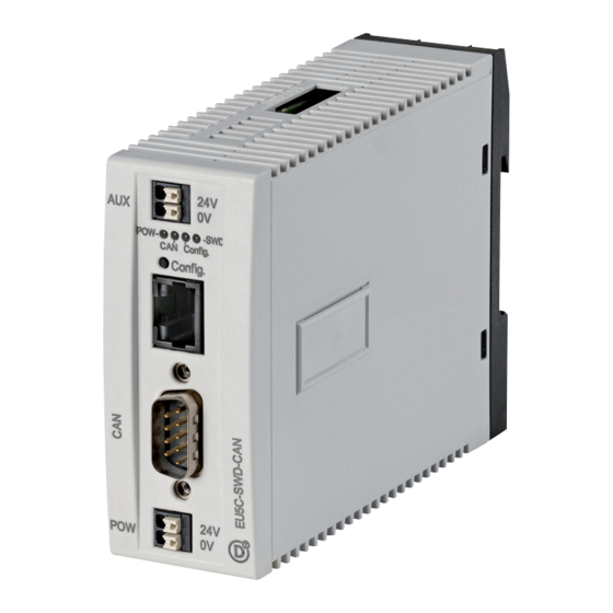
Page 36: Eu5C-Swd-Can
02/11 MN05006002Z-EN Engineering SmartWire-DT CANopen gateway EU5C-SWD-CAN In connection with the SmartWire-DT slaves the gateway functions on the CANopen bus as a modular slave in accor- dance with profile DS301.4, each SmartWire-DT slave being an own module. Table 8: Features of the SmartWire-DT CANopen gateway CANopen Baud rate max. - Page 37 Connection of the SmartWire-DT network to the SmartWire- DT gateway and to the SmartWire-DT power feeder module is always performed via the 8-conductor SmartWire-DT ribbon cable. With a cross-sectional area of 0.23 mm²...
- Page 38 SmartWire-DT gateway must not exceed 0.7 A. Otherwise a power feeder module EU5C-SWD-PF2-1 has to be used before the SmartWire-DT slave as of which the 0.7 A has been exceeded. Add together the currents of all SmartWire-DT slaves and...
-
Page 39: Contactor Supply Uaux
> 72 W/3 A, a power feeder module EU5C-SWD-PF1-1, EU5C-SWD-PF2-1 or a switch cabinet bushing has to be inserted before the SmartWire-DT slave as of which the 3 A have been exceeded. The total current I is is the sum of the contactors‘... -
Page 40: Voltage Drop
02/11 MN05006002Z-EN Engineering Example: With an utilization factor k = 0.6, 10 contactors of the part no. DILM38 can be supplied by an SmartWire-DT gateway or an SmartWire-DT power feeder module. Voltage Drop Extensive SmartWire-DT networks with long line lengths (up... - Page 41 SmartWire-DT topology? L[m] Figure 4: Line resistance of SmartWire-DT ribbon and round cable in the device and contactor supplies a Round cable in the device supply b Round cable in the contactor supply c Ribbon cable in the device supply d Ribbon cable in the contactor supply www.comoso.com...
- Page 42 02/11 MN05006002Z-EN Engineering Calculation of the voltage drop in the device supply The operability of an SmartWire-DT slave is guaranteed at a supply voltage U for the devices in the range of +15 V DC (tolerance range -30 %/+20 %), i.e. +10.50 - +18.0 V DC.
- Page 43 U f of 10.5 V DC. First determine the total current by adding the current consumption of all SmartWire-DT slaves as listed in the tables in the appendix of manual MN05006001Z-EN, “SmartWire-DT Slaves”, including the current consump- tion of the network connection (17 mA).
- Page 44 “Slave n” using the formula: x (I If this rough calculation yields an excessively low supply voltage at an SmartWire-DT slave “n” does it have to be calculated as of what network position the minimum supply voltage U = 10.5 V DC is achieved. An addi-...
- Page 45 How do I dimension the power supply of my SmartWire-DT topology? • I = Total current in the SmartWire-DT network that is supplied by a supply unit. • I = The current that flows through the network termina- tion can be assumed as being 17 mA.
- Page 46 Example for calculation of the voltage drop in the device supply a 6 contactors DILM38 (with DIL-SWD-032-002), simultaneity factor k = 0.8 b 2 SmartWire-DT I/O modules (EU5E-SWD-4D4D) c 3 function elements M22-SWD-K11LED-W d Network termination (SWD4-RC8-10) Total length of the ribbon cable: 8 m...
- Page 47 02/11 MN05006002Z-EN How do I dimension the power supply of my SmartWire-DT topology? The SmartWire-DT gateway is supplying the SmartWire-DT topology sufficiently. Calculation of the voltage drop in the contactor supply DC operated contactors with the control voltage U +24 V DC switch dependably in the range +24 V DC (-20 %/+10 %), i.e.
- Page 48 = 0.8. a 9 contactors DILM38 (with DIL-SWD-032-002), simultaneity factor k = 0.8 b 2 SmartWire-DT I/O modules (EU5E-SWD-4D4D) c 3 function elements M22-SWD-K11LED-W d Network termination (SWD4-RC8-10) e Position for an additional power feeder module (EU5C-SWD-PF1-1) www.comoso.com...
-
Page 49: How Do I Position My Smartwire-Dt Slaves
There are no restrictions to the positioning. However, the SmartWire-DT slaves? following recommendations should be heeded: Arrange the SmartWire-DT slaves of a device group as far as possible in groups on the SmartWire-DT network. Fit the external device plug to the ribbon cable with suffi- cient spacing. - Page 50 02/11 MN05006002Z-EN www.comoso.com...
- Page 51 02/11 MN05006002Z-EN Installation The SmartWire-DT components must only be installed and connected up by trained electricians or other persons who are familiar with the mounting of electrical equipment. Danger of electric shock! Never carry out electrical work on the device while the power supply is switched on.
- Page 52 02/11 MN05006002Z-EN Installation Mechanical Mounting SmartWire-DT gateways, SmartWire-DT I/O modules and SmartWire-DT power feeder modules are suitable for mounting on a top-hat rail in accordance with IEC/EN 60715, 35 mm. When fitting the gateway, first set the field bus station address using the dip switches (switches 2 - 8) on the right side of the SmartWire-DT gateway.
- Page 53 02/11 MN05006002Z-EN Electrical Installation Electrical Installation Potential conditions between the components The entire SmartWire-DT topology operates with a common device supply voltage. The field bus and the SmartWire-DT topology are electrically isolated from one another. SmartWire-DT gateway Figure 8: SmartWire-DT gateway...
- Page 54 EMERGENCY STOP switching by group is performed exter- nally by switching off the 24 V DC control voltage of the contactor coils. See also manual MN05006001Z-EN, “SmartWire-DT Slaves” Connecting the POW supply voltage The device supply voltage for the electronics of all Smart-...
- Page 55 Wire-DT ribbon cable with fitted blade terminal (at the cable’s gateway end). Caution! Make the SmartWire-DT network connections only in a voltage-free state. Connect PROFIBUS-DP bus Connect the PROFIBUS-DP cable by means of the PROFIBUS- DP plug to the field bus interface of the SmartWire-DT gateway. www.comoso.com...
- Page 56 For connection to the CANopen cable you require a 9-pole SUB-D socket (e.g. PS416-ZBS-411). Connect the CANopen cable by means of the CANopen plug to the field bus interface of the gateway. For detailed instructions for connecting a SmartWire-DT gateway, see manual MN05013002Z-EN, “SmartWire-DT Gateways”. www.comoso.com...
- Page 57 02/11 MN05006002Z-EN Electrical Installation SmartWire-DT power module The SmartWire-DT power modules EU5C-SWD-PF1-1 and EU5C-SWD-PF2-1 provide an additional power supply for stations in the SmartWire-DT network. Figure 10: Connections of the SmartWire-DT power supply module (here the EU5C-SWD-PF2 is used for illus-...
- Page 58 Connecting the POW supply voltage EU5C-SWD-PF2: the device supply voltage for the electronics of all SmartWire-DT slaves (15 V DC) is generated from the 24 V DC supply voltage that you apply to the spring-cage terminal connection POW.
- Page 59 Electrical Installation SmartWire-DT I/O modules The SmartWire-DT I/O modules connect sensors and actua- tors to the SmartWire-DT network. A range of modules with various combinations of digital or analog inputs and outputs are available. The SmartWire-DT family of I/O modules is being continually expanded.
- Page 60 02/11 MN05006002Z-EN Installation Figure 11: Connections of a SmartWire-DT I/O module a SmartWire-DT ribbon cable with external device plug b Status SmartWire-DT LED c Status LEDs of the inputs and/or outputs d Digital inputs and/or outputs e 0 V connection and/or 0 V/24 V connection with a combined...
- Page 61 DIL-SWD-32-001 DIL-SWD-32-002 Figure 12: Surface mounting of the SmartWire-DT modules DIL-SWD-32-001 and DIL-SWD-32-002 for DILM a Connection of SmartWire-DT external device plug b Mechanical switching position indicator c Diagnostics LED d Catch slider e Connection pins f Adjusting slide for contactor size...
- Page 62 M22-SWD… function elements The M22-SWD… function elements are combined together with front elements of the RMQ-Titan system to form pilot devices that communicate via the SmartWire-DT network. The M22-SWD… function elements are each available in two versions for front or base fixing.
- Page 63 02/11 MN05006002Z-EN Electrical Installation Figure 13: M22-SWD… function elements www.comoso.com...
- Page 64 Function element with 3 positions and Bezels LED for front mount Link for external device plug Indicator lights SmartWire-DT external device plug Key-operated buttons SmartWire-DT flat band conductor Selector switch actuators Planning and ordering help (SWD?Assist) Pushbutton actuators...
- Page 65 02/11 MN05006002Z-EN Electrical Installation M22-SWD front mount M22-SWD front function elements are used in connection with the M22-A adapter and M22 front elements for instal- lation in consoles or switch cabinet doors. They replace the familiar M22-K10-/K01 contact elements and M22-LED… indication elements.
- Page 66 Connection of the M22 function element to the SmartWire-DT flat ribbon cable Fit the external device plug to the ribbon cable Plug the M22-SWD front function element onto the external device plug. Wire a SmartWire-DT contact element. Fit the M22 front element. www.comoso.com...
- Page 67 M22-K10-/K01 and indicator elements M22 LED. On the front panel the existing elements are used for the control circuit function. The elements are connected to the SmartWire-DT network through this circuit-board, which features a switchable network termination.
- Page 68 Connection on the PCB is performed via eight numbered and colour-coded spring-cage terminals. This applies to the incoming SmartWire-DT cable on the PCB side marked IN and to the outgoing SmartWire-DT cable on the OUT side. The SmartWire-DT round cable and SmartWire-DT enclosure bushings have the same wire colours.
- Page 69 Direct connection of SmartWire-DT round cable V-M20 Figure 18: Direct connection with a cable gland Jacket and insulate the SmartWire-DT round cable to a suitable length. Fit the individual wires with insulated ferrules with plastic collars in accordance with DIN 46228, Part 4, of suitable cross-section and a length of at least 8 mm.
- Page 70 If further SmartWire-DT slaves follow this surface mounting enclosure with SmartWire-DT slaves, a cable plug (part no. SWD4-SM8-67 straight or part no.SWD4-SM8-67W angled at 90°) is fitted to the outgoing SmartWire-DT round cable (a “Housing bushing with socket“, page 78). So fasten the enclosure bushing socket (part no.
- Page 71 02/11 MN05006002Z-EN Electrical Installation M22-SWD4-SM8-20 M22-SWD4-SF8-20 O F F M22-I… O F F M22-I… M22-SWD4-SM8-20 M22-SWD4-SF8-20 Figure 20: Incoming and outgoing SmartWire-DT round cables with different installation positions www.comoso.com...
- Page 72 GND: device supply voltage g yellow, earth: contactor control voltage h green, +24 V DC: contactor control voltage If further SmartWire-DT slaves follow this surface mounting enclosure with SmartWire-DT slaves: Clamp all outgoing wires according to colour in the spring- cage terminals marked with the same colours on the OUT side.
- Page 73 Switch the network termination to the position ON, if this surface mounting enclosure houses the last SmartWire-DT slave. Caution! The network termination must be switched without fail to the position OFF, if further SmartWire-DT slaves follow the surface mounting enclosure with SmartWire-DT slaves. www.comoso.com...
- Page 74 Switch cabinet bushing Use the switch cabinet bushing for external connection of the SmartWire-DT network to a switch cabinet or enclosure. This is not given a slave address. There is voltage reversal and EMC protection for an externally supplied 24 V DC control voltage.
- Page 75 02/11 MN05006002Z-EN Electrical Installation Switch cabinet bushing with a round socket o 18.5 mm (o 0.73”) 4 mm 0.16”) S W D 4 -S F L 8 -2 0 Figure 23: Switch cabinet bushing with a round socket To exit the switch cabinet in the direction of the SmartWire- DT network end and the round socket is therefore carrying a live voltage, use the switch cabinet bushing with a built-in round socket (part no.
- Page 76 DT round cable with a fitted round plug (part no. SWD4- SM8-67 straight or part no. SWD4-SM8-67W angled at 90°). How to connect a round plug to the SmartWire-DT round cable is described on page 82. Switch cabinet bushing with round plug o 18.5 mm...
- Page 77 (part no. SWD4-SF8-67 flat or part no. SWD4-SF8-67W, angled at 90°). How to connect a round socket to the SmartWire-DT round cable is described on page 81. The ribbon cable with an attached blade terminal used within the switch cabinet is plugged into the socket of the switch cabinet bushing.
- Page 78 The switch cabinet bushing interrupts the two conductors for the contactor control voltage (earth and 24 V DC) and conducts them to the spring-cage terminals A and B. The remaining conductors between the SmartWire-DT ribbon cable and round cable connection are connected throughout...
- Page 79 0 V and A: 24 V to B: 24 V, as shown in the covered by the connected or with a round plug above illustration, “Connections of the supply unit (SmartWire-DT (part no. SWD4-SML8- switch cabinet bushing”. gateway or power feeder 20).
- Page 80 02/11 MN05006002Z-EN Installation Terminal capacities of the cables for the 24 V DC external power supply • solid: 0.2 - 1.5 mm (AWG 24-16) • flexible 0.25 - 1.5 mm (AWG 24-16) with appropriate isolated ferrules with plastic collars in accordance with DIN 46228, Part 4, minimum length 8 mm.
- Page 81 You lead the SmartWire-DT network via the SmartWire-DT round cable with a fitted round socket (part no. SWD4-SF8- 67 straight or part no. SWD4-SF8-67W angled at 90°). How to connect a round socket to the SmartWire-DT round cable is described on page 81. www.comoso.com...
- Page 82 (part no. SWD4- SM8-67 straight or part no. SWD4-SM8-67W angled at 90°). How to connect a round plug to the SmartWire-DT round cable is described on page 82. Link for PCB base/external device plug front...
- Page 83 Electrical Installation Figure 28: Link for PCB base Caution! External device plugs that are not fitted to a SmartWire-DT slave must be fitted with a link SWD4-SEL8-10. This ensures a correct address assignment to subsequent SmartWire-DT slaves during the configuration process (when the Config.
- Page 84 02/11 MN05006002Z-EN Installation Connecting the Smart- SmartWire-DT slaves in the control panel are connected with Wire-DT connection cable 8 pole ribbon cable SWD4-…LF…. Outside the control panel they are connected with round cable SWD4…LR8-24. Connecting the SmartWire-DT ribbon cable SmartWire-DT slaves and some other SmartWire-DT elements are connected through a SmartWire-DT ribbon cable.
- Page 85 Connect round socket to SmartWire-DT round cable Figure 29: Straight round socket with screw locking for the SmartWire-DT round cable Fit (solder) the round socket to the SmartWire-DT round cable. Warning! Connection of the movable soldering lugs on the round socket may be performed only with the use of shrink sleeve insulation on the individual conductors.
- Page 86 Connect round plug to the SmartWire-DT round cable Figure 31: Straight round plug with screw locking for the SmartWire-DT round cable Fit (solder) the round plug to the SmartWire-DT round cable. Figure 32: Solder view of the round plug a brown, +15 V DC: device supply voltage...
- Page 87 Fitting SmartWire-DT ribbon cable with plugs Depending on the purpose fit a blade terminal or external device plug to the SmartWire-DT ribbon cable. The plugs are connected firmly and permanently to the SmartWire-DT ribbon cable by means of a suitable crimper.
- Page 88 02/11 MN05006002Z-EN Installation Figure 34: SmartWire-DT ribbon cable with blade terminal at the beginning and end Push the open blade terminal, with the transparent top part of the plug pointing upwards, into the crimper guide up to the stop pin (part no. SWD4-CRP-2).
- Page 89 When inserting the ribbon cable into the plug, check which cable end you are working on. Make sure that the cut edge of the 8-pole SmartWire-DT ribbon cable is flat and right-angled. Plug for gateway end of cable When introducing the ribbon cable into the plug, the ribbon cable imprint is on its underside, i.
- Page 90 02/11 MN05006002Z-EN Installation Plug for far end of cable When introducing the ribbon cable into the plug, the ribbon cable imprint is on the top of the cable and therefore visible. The arrow on the ribbon cable points towards the plug. SW D 4- 8S F2 Push the ribbon cable up to the stop via the guide in the bottom part of the crimper between the blade contacts of...
- Page 91 02/11 MN05006002Z-EN Connecting the SmartWire-DT connection cable Figure 36: Slide the SmartWire-DT ribbon cable into the blade terminal Warning! For correct polarity the black conductor of the ribbon cable must be lying next to the white stripe on the bottom part of the crimper.
- Page 92 (M22-SWD-SEL8-10). Figure 37: SmartWire-DT external device plug On the basis of the position of the SmartWire-DT slave determine where the first external device plug has to be fastened to the ribbon cable. Leave sufficient space between two external device plugs.
- Page 93 SW D 4- 8S F2 SW D 4- 8S F2 SW D 4- 8S F2 Figure 39: SmartWire-DT device plug with correct polarity Caution! Correct polarity is ensured with this arrangement. The black conductor of the ribbon cable lies under the cable with the designation +15 V shown black on the top part of the plug.
- Page 94 Should the topology change and no more Smart- Wire-DT slaves are to be connected here, this plug is replaced by an SmartWire-DT link element (part no. SWD4-SEL8-10), a section “Link for PCB base/external device plug front”, page 78.
- Page 95 + 15 V SWD4-8SFF2-5 Figure 41: Connect SmartWire-DT ribbon cables with a coupling for an 8-pole blade terminal Insert the ribbon cable into the coupling guide so that the black arrow on the ribbon cable is pointing in the same direction as the black arrow on the coupling.
- Page 96 The ribbon cable with an attached blade terminal is plugged into the socket. a b c d e f g h Figure 42: SmartWire-DT blade terminal/round cable adapter with configuration of the spring-cage terminal connection a brown, +15 V DC: device supply voltage...
- Page 97 Network termination for an installed ribbon cable If the SmartWire-DT network ends with a ribbon cable, a ribbon cable plug must be connected there. Connect the ribbon cable to the SmartWire-DT network termination (part no.
- Page 98 Figure 43: SmartWire-DT:Network terminator for ribbon cable Network termination for an installed round cable If you are using as the last SmartWire-DT element on the SmartWire-DT network a surface mounting enclosure with an inlaid PCB (M22-SWD-I…-LP01) that is connected via a round cable, use the integrated network termination.
- Page 99 The EMC of the system SmartWire-DT is ensured when the following rules are observed: • Proper and extensive earthing of the inactive metal parts •...
- Page 100 The SmartWire-DT system is not designed for transmitting safety-relevant signals. To find out how the SmartWire-DT system can be used for safety-related switching off, see manual MN05006001Z- EN, “SmartWire-DT Slaves”. www.comoso.com...
- Page 101 02/11 MN05006002Z-EN Commissioning The commissioning of an SmartWire-DT network always takes place in connection with the SmartWire-DT gateway and the overriding controller (PLC) with its field bus connec- tion. Commissioning of the various SmartWire-DT gateways and controllers are described in separate manuals.
- Page 102 SmartWire-DT gateway or power feeder module. Check whether: • All plugs on the SmartWire-DT cable are correct, i.e. are connected in accordance with the installation instructions in the subsection „Fitting SmartWire-DT ribbon cable with plugs“, page 83.
- Page 103 After initial switch-on of the supply voltage the SmartWire- SmartWire-DT network DT gateway determines which and how many SmartWire-DT slaves are connected to the SmartWire-DT network. As yet no configuration exists in the SmartWire-DT gateway. Status messages of the SmartWire-DT gateway after...
- Page 104 SmartWire-DT coupling unit checks each time the voltage supply is retriggered on whether the number and part no. of SmartWire-DT slaves present on the SmartWire-DT network are unchanged and whether the SmartWire-DT topology is functional with these.
- Page 105 SmartWire- ration. Among other things define the number, part no. and DT network sequence of SmartWire-DT slaves and which SmartWire-DT coupling unit is being operated (PROFIBUS-DP slave or CAN device). The following files are used for integration of the SmartWire- DT gateway into the control configuration: •...
- Page 106 “SmartWire-DT Gateways”. Switch-on in case of a changed actual configuration If. after switching on, the SmartWire-DT coupling unit ascer- tains a deviation in the number or part no. of SmartWire-DT slaves between the actual and target configurations, it reacts as follows: •...
- Page 107 In the case of a changed actual configuration the continued behavior of the operator is governed by whether the change has been created deliberately or by an unwanted influencing of the SmartWire-DT topology. In any case the following is valid: Prior to reconfiguration interrupt the connection to the field bus master by pulling out the field bus plug.
- Page 108 Wire-DT slaves is no longer being found by the SmartWire- DT gateway. Then check where there is a possible damage to the SmartWire-DT cable or an SEL link is missing. If an SmartWire-DT slave is no longer connected, the SWD LED is switched off.
- Page 109 Retriggering on in the case of an unchanged configu- ration Normally , if the actual, target and project configurations agree, the SmartWire-DT gateway changes over to the SmartWire-DT mode “Normal” and is ready for data inter- change. Table 16: LED of SmartWire-DT gateway after change to SmartWire-DT modus “Normal”...
- Page 110 02/11 MN05006002Z-EN Commissioning www.comoso.com...
- Page 111 02/11 MN05006002Z-EN What Happens If …? Check the condition of the SmartWire-DT gateway and of the SmartWire-DT slaves by means of the status LEDs and diag- nostic bits. The diagnoses of the various SmartWire-DT components and controllers are described in separate manuals.
- Page 112 SmartWire-DT gateway, but the deviation allows data exchange with the relevant SmartWire-DT slaves. LED orange At least one SmartWire-DT slave requests a diag- Check your target configura- continuous nosis test, because, e.g. SmartWire-DT slaves are tion and, if necessary,...
- Page 113 02/11 MN05006002Z-EN Behavior of the SmartWire-DT gateway CAN LED (status of CANopen field bus) Table 19: Diagnosis with the aid of the CAN LED Event Explanation Remedy LED green contin- Operational status: Data exchange takes place – uous light through the CAN bus.
- Page 114 LED green contin- The project configuration of the – uous light controller agrees with the target config- uration of the SmartWire-DT gateway. LED off No communication with the field bus Check the connection to the field master or the SmartWire-DT coupling...
- Page 115 02/11 MN05006002Z-EN Behavior of the SmartWire-DT gateway SWD LED (status of SmartWire-DT network) Table 21: Diagnostics with the SWD-LED Event Explanation Remedy LED green contin- All SmartWire-DT slaves stored in the – uous light target configuration are available. LED red contin-...
- Page 116 02/11 MN05006002Z-EN What Happens If …? Table 22: Combined indication of DP or CAN LED, Config. LED and SWD LED in firmware update mode Event Explanation Remedy All three LEDs are a The gateway is in firmware update mode. – continuous orange All three LEDs are a The gateway is in firmware update mode.
- Page 117 02/11 MN05006002Z-EN Behavior of the SmartWire-DT powerfeed modules Behavior of the The status of an SmartWire-DT power feeder module EU5C- SmartWire-DT powerfeed SWD-PF1-1 or EU5C-SWD-PF2-1 is signalled optically via the modules front panel LED POW. Event Explanation Remedy LED yellow 15 V DC device voltage OK.
- Page 118 02/11 MN05006002Z-EN What Happens If …? Behaviour of The status of a SmartWire-DT module DIL-SWD-32-001/ SmartWire-DT modules DIL-SWD-32-002 is signalled optically via the front panel DIL-SWD-32-… LED Ready. The Ready LED can assume the colours green or yellow. It indicates the statuses that are influenced via the SmartWire- DT network, i.e.
- Page 119 Only in position A and with a functioning SmartWire-DT network does the status indicated by the Ready LED on the DIL-SWD-32-002 comply with the actual switch position of the contactor.
- Page 120 The mechanical switch position indicator of a DIL-SWD-32-… module shows unambiguously the actual switch position. Behavior of SmartWire-DT The status of an SmartWire-DT function element M22- function elements SWD… is signalled optically via the green SWD-LED with a M22-SWD…...
- Page 121 02/11 MN05006002Z-EN Appendix Approval and Certification SmartWire-DT components are approved for several coun- tries and regions. Approvals and national approvals for the SmartWire-DT system Product • CE Conformity; standards • UL 508 (INDUSTRIAL CONTROL EQUIPMENT); • CSA C22.2 No. 142-M1987 (Process Control Equipment);...
- Page 122 02/11 MN05006002Z-EN www.comoso.com...
- Page 123 02/11 MN05006002Z-EN Index Actuators ............15 AUX supply voltage Cable protection ...........51 Terminal capacities of the cables ....50 Blade terminal Figure ............83 fitting to the end of the cable .......88 Installation ...........83 Cable -socket, configuration ........81 Cable plug Configuration ..........82 CAN-LED Diagnostics ..........109 CANopen gateway ..........15 CANopen network...
- Page 124 CANopen .............52 Enclosure bushing ........77 Field bus ............51 M22-SWD............58 Power feeder module ........53 PROFIBUS-DP ..........51 SmartWire-DT contactor modules ....57 SmartWire-DT network .........51 Supply voltage POW ........54 Switch cabinet bushing ........70 Connecting POW, supply voltage ......54 Connection AUX ............50, 54 POW ............50, 54...
- Page 125 02/11 MN05006002Z-EN Index Earth-free Operation ..........96 Earthing of inactive parts ........95 EDS description file ..........101 Electrical load Calculation ...........33 Electrical load, calculation In the contactor supply .........35 In the device supply ........34 Electromagnetic compatibility (EMC) ....95 Electronic Data Sheet ........101 EMC = Electromagnetic Compatibility ....95 EMC Directive ............95 EMV Planning ............95...
- Page 126 (sequence) ............47 LED indication After the creation of a new target configuration ..........24 LED indication, SmartWire-DT gateway After changeover to the SmartWire-DT mode “Normal” ...........105 In the case of a changed actual configuration ..........102 In the case of a project configuration deviation ............19...
- Page 127 Connecting bus ..........51 Gateway ............15 Ribbon/round cable, component adapter .....92 Round cable, network termination for an installed ............94 Sensors ..............15 Simultaneity factor k ..........35 SmartWire-DT Accessories ...........20 Flat band conductor ........26 Function elements ........16 Inputs/outputs modules ........15 Network ............21 Network terminator ........19 Network, physical properties ......26...
- Page 128 SmartWire-DT coupling Using for ribbon cables ........91 SmartWire-DT coupling unit Retriggering on in the case of an unchanged configuration ..........105 SmartWire-DT external device plug Correct polarity ..........89 Crimping in the crimper ........90 Sufficient cable length ........88 SmartWire-DT flat band conductor Cable resistance ...........36...
- Page 129 02/11 MN05006002Z-EN Index SmartWire-DT power feeder module Mounting .............48 SmartWire-DT power modules Connecting ...........53 SmartWire-DT PROFIBUS-DP gateway ....31 SmartWire-DT ribbon cable Connecting ...........80 Fitting with plugs .........83 SmartWire-DT round cable Cable resistance ...........36 Connecting ...........80 Direct connection .........65 Incoming ............66 Outgoing ............66...
- Page 130 02/11 MN05006002Z-EN Switch on, SmartWire-DT gateway In the case of a changed actual configuration ..........102 In the case of a changed project configuration ..........104 Target group ............7 Universal module ..........17 Voltage Drop ............36 www.comoso.com...
Need help?
Do you have a question about the SmartWire-DT and is the answer not in the manual?
Questions and answers