
Subscribe to Our Youtube Channel
Related Manuals for Eaton SWIRE-GW-MB


Summary of Contents for Eaton SWIRE-GW-MB
- Page 1 07/09 MN03407002Z-EN Manual replaces 07/09 AWB1251-1616en Connection System SmartWire SWIRE-GW-MB...
- Page 2 German manual. published 2008, edition date 11/08, edition 07/09, See revision protocol in the “About this manual“ chapter © 2008 by Eaton Industries GmbH, 53105 Bonn Production: René Wiegand Translation: globaldocs GmbH All rights reserved, including those of the translation.
- Page 3 Danger! Dangerous electrical voltage! Before commencing the installation • Disconnect the power supply of the device. • Suitable safety hardware and software measures should be implemented for the • Ensure that devices cannot be accidentally I/O interface so that a line or wire breakage restarted.
- Page 4 • Measures should be taken to ensure the • Wherever faults in the automation system proper restart of programs interrupted may cause damage to persons or property, after a voltage dip or failure. This should external measures must be implemented to not cause dangerous operating states even ensure a safe operating state in the event for a short time.
-
Page 5: Table Of Contents
07/09 MN03407002Z-EN Contents About this manual List of revisions Target group Additional device manuals Reading conventions Gateway MODBUS RTU SWIRE-GW-MB System overview Design of the SWIRE-GW-MB Functional description Example for SmartWire Module – SmartWire module for DILM – SmartWire-I/O module... - Page 6 Access methods to the register areas MODBUS-functions – Structure of a MODBUS message – Write commands – Read commands MODBUS diagnostic functions (0x08) – Polling device information for SWIRE-GW-MB – Diagnostic data – Checking the SmartWire configuration Fault-finding Appendix Technical data –...
-
Page 7: About This Manual
(previously AWB2528+1251-1589GB), • Connection system SmartWire SWIRE-GW-DP MN03407001Z-EN (previously AWB1210+1251-1590GB). The manuals are available for download as PDF files from the Eaton website. To find the document quickly go to http://www.moeller.net/en/support/index.jsp and enter the document number as a search term. -
Page 8: Reading Conventions
07/09 MN03407002Z-EN About this manual Reading conventions Symbols used in this manual have the following meanings: Indicates instructions to be followed. Caution! Warns of a hazardous situation that could result in damage to the product or components. Warning! Warns of the possibility of serious damage and slight injury. -
Page 9: Gateway Modbus Rtu Swire-Gw-Mb
SWIRE-GW-MB The communication module SWIRE-GW-MB has been developed for automation tasks with the PROFIBUS-DP field bus. SWIRE-GW-MB provides a gateway between the MODBUS RTU field bus system and the SmartWire connection system and can be used only in combination with SmartWire. -
Page 10: System Overview
Figure 1: Gateway MODBUS SWIRE-GW-MB in network a Master area (PLC or PC) b Slave area with SmartWire system The SWIRE-GW-MB gateway and the components of the SmartWire system are built-in devices. They must be installed in an enclosure, switch cabinet or distribution... -
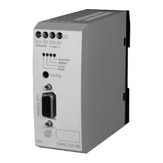
Page 11: Design Of The Swire-Gw-Mb
07/09 MN03407002Z-EN Design of the SWIRE-GW-MB Design of the The illustration below shows the SWIRE-GW-MB. SWIRE-GW-MB Figure 2: Device view a MODBUS-RTU connection through 9-pole SUB-D socket b Configuration button c Status LEDs d Gateway power supply terminals e Contactor coil (Aux) power supply terminals... -
Page 12: Example For Smartwire Module
07/09 MN03407002Z-EN Gateway MODBUS RTU SWIRE-GW-MB Example for SmartWire SmartWire module for DILM Module The illustration below shows the SmartWire module for DILM. Figure 3: Surface mounting of SmartWire-Modul for DILM a IN and OUT sockets for the connection cable... -
Page 13: Smartwire-I/O Module
07/09 MN03407002Z-EN Example for SmartWire Module SmartWire-I/O module The illustration below shows the SmartWire I/O module. Figure 4: SWIRE-4DI-2DO-R a Socket In for SmartWire connection cable b Socket Out for SmartWire connection cable c Terminals for elay output Q1 d Terminals for Inputs I1 and I2 e Green LEDs f Terminals for Inputs I3 and I4 g Terminals for relay output Q2... - Page 14 07/09 MN03407002Z-EN...
-
Page 15: Installation
This section tells you how to set up the station addresses and protocol parameters for MODBUS RTU. MODBUS RTU station To be able to use the gateway SWIRE-GW-MB within a addresses and protocol MODBUS RTU network, its station address, parity and baud parameters rate must be set before use. - Page 16 (1 or 2). The illustration below shows the DIP switches on the gateway device’s underside. Figure 5: Bottom of device SWIRE-GW-MB The following illustration shows the gateway’s default (factory set) DIP switch positions.
-
Page 17: Connect Smartwire Connection Cable
07/09 MN03407002Z-EN Connect SmartWire connection cable Figure 6: Initial DIP switch positions of SWIRE-GW-MB (address 31, even parity, one stop bit, baud rate = 57.6 kbits/s) On the DIP switch (Fig. 7) on the device underside, set the gateway’s station address, parity and baud rate. -
Page 18: Connecting The Power Supply
The overall length of the SmartWire line may not exceed a maximum of 4 m. Connecting the power The gateway SWIRE-GW-MB is operated with a 24 V DC supply supply voltage. An additional 24 V DC control voltage is provided for the contactor coils. - Page 19 07/09 MN03407002Z-EN Connecting the power supply L01+ L01– = 24 V H (20.4 – 28.8 V H) 0.6 Nm 0.6 x 3.5 0V24V 0V Figure 9: Connecting the power supply The terminals are suitable for AWG22 to AWG16 cables and for flexible cables with a cross-section of 0.5 to 1.5 mm².
-
Page 20: Connecting Modbus Rtu
Caution! RS232 should be used only for point-to-point connections between the SWIRE-GW-MB and a PLC or PC. Caution! For communication through RS232 use only pins 2, 3 and Using preassembled data cables that use pins 6, 8 and 9 can damage the SWIRE-GW-MB or the other connected device. -
Page 21: Data Transfer With Rs485
07/09 MN03407002Z-EN Connecting MODBUS RTU The following table lists the signals of SWIRE-GW-MB. Table 3: Signals SWIRE GW-MB Signal name Designation Not used – RxD out RS232 transmit TxD in RS232 receive Not used – Reference potential + 5V + 5V, electrically isolated Not used –... - Page 22 07/09 MN03407002Z-EN Installation Pin functions RS485 SWIRE-GW-MB Rx/Tx - (A-Line) Rx/Tx + (B-Line) Figure 11: Terminal assignment RS485 Table 4: SWIRE-GW-MB signals Signal name Designation Not used – RxD out RS232 transmit TxD in RS232 receive Not used – Reference potential...
-
Page 23: Terminating Resistors
07/09 MN03407002Z-EN Terminating resistors Terminating resistors If the RS485 communication standard is used, the first and last station in a MODBUS RTU field bus segment must terminate the field bus with an energized termination resistor. The bus termination resistor is connected externally, either as a separate terminating resistor or through a special D-sub connector with built-in bus termination. - Page 24 07/09 MN03407002Z-EN Installation for top-hat rail for mounting plate ZB4-102-KS1 ZB4-102-KS1 KLBü 3-8 SC FM 4/TS 35 (Weidmüller) (Weidmüller) Figure 12: Shielding of network cable Caution! Potential equalisation currents may not flow on the shield. A safe method of equipotential bonding must be provided to ensure this.
-
Page 25: Potential Separation
07/09 MN03407002Z-EN Potential separation Potential separation The following electrical isolation measures apply for the SWIRE-GW-MB interfaces: • Potential isolation of the MODBUS-RTU to the supply voltage and to the SmartWire system • No isolation between the supply voltage for the gateway and the supply voltage for the contactor coils •... - Page 26 07/09 MN03407002Z-EN...
-
Page 27: Commissioning
Die gateway’s LEDs now indicate the following states: • The ready LED of the SWIRE-GW-MB flashes. • The U-Aux LED of the SWIRE-GW-MB is permaneltly ON. • The MODBUS-RTU-LED is OFF (no communication via MODBUS-RTU). • The SmartWire LED flashes as the SmartWire slaves have not yet been configured. -
Page 28: Meaning Of The Status Leds
SWIRE-GW-MB indicates send and receive data transfer activity with a yellow flashing or constantly lit MODBUS RTU LED. Meaning of the status The gateway SWIRE-GW-MB has four status LEDs. These are LEDs green (UAUX, Ready and SmartWire) and yellow (MODBUS RTU). -
Page 29: Smartwire Led
07/09 MN03407002Z-EN Meaning of the status LEDs SmartWire LED continuous SmartWire system is ok light No supply voltage available on the MODBUS gateway Fast flashing Transmission error in the SmartWire system Slow flashing Error in the configuration of the SmartWire system, target and actual configuration do not match MODBUS-RTU-LED continuous... - Page 30 07/09 MN03407002Z-EN...
-
Page 31: Operation Through Modbus Rtu
The MODBUS gateway SWIRE-GW-MB has a built-in adjustable watchdog timer (see section "Setting the watchdog timer", page 43), which triggers a fault state in the gateway if MODBUS communication fails. To prevent timeouts, the control data from the SWIRE-GW-MB should be written periodically. -
Page 32: Data Mapping Of Smartwire Stations
For the MODBUS RTU gateway the status and control data for the connected SmartWire stations are saved to the holding register of the SWIRE-GW-MB, which contains the following data: • Status information (input data) of the SmartWire stations •... -
Page 33: Data Diagram
07/09 MN03407002Z-EN Data mapping of SmartWire stations Designation Register area Data width: Diagram Number of SmartWire 40143 2 bytes binary diagram stations Watchdog timer (non- 44097 2 bytes Low byte: retentive) Time = value × 10 ms High byte: not assigned Watchdog-Timer 44098 2 bytes... - Page 34 07/09 MN03407002Z-EN Operation through MODBUS RTU Table 7: Arrangement of register contents Register area Bit no. Data content No. of SmartWire station 40007 0 (LSB) Status bit 1 1 slave Status bit 2 1 slave Status bit 1 2 slave Status bit 2 2 slave Status bit 1...
-
Page 35: Abbreviated And Full Bit Representation
07/09 MN03407002Z-EN Data mapping of SmartWire stations Abbreviated and full bit representation Depending on the register data area, the status data (input data of the SmartWire stations) and control data (output data of the SmartWire stations) are output either in an abbreviated form or in full. - Page 36 07/09 MN03407002Z-EN Operation through MODBUS RTU Example: Status and control data of SWIRE-DIL and SWIRE-4DI-2DO-R SWIRE-DIL has the following status and control data: Table 8: Control data (write data, as seen from MODBUS RTU masters) SWIRE-DIL Bit 3 Bit 2 Bit 1 Bit 0 Contactor actuation...
- Page 37 07/09 MN03407002Z-EN Data mapping of SmartWire stations Table 11: Definition of the bit Value Contactor status PKZ status SWIRE-DIL status bit Fault SWIRE-4DI-2DO-R has the following status and control data: Table 12: Control data (write data, as seen from MODBUS RTU masters) SWIRE-DIL Bit 3...
- Page 38 07/09 MN03407002Z-EN Operation through MODBUS RTU Table 14: Status data (read data, as seen from MODBUS RTU master) SWIRE-4DI-2DO-R Bit 7 Bit 6 Bit 5 Bit 4 Bit 3 Bit 2 Bit 1 Bit 0 Status input I1 Status input I2 Status input I3 Status input I4 Status bit...
- Page 39 07/09 MN03407002Z-EN Data mapping of SmartWire stations Table 16: Register view, abbreviated status and control data Register 15 40001 40002 40007 40008 40010 40011 40012 40013 Sx = number of SWIRE station, Qy = control bit y of station x, Iy = status bit y of station x Table 17: Abbreviated status and control data views SmartWire Abbreviated control...
- Page 40 07/09 MN03407002Z-EN Operation through MODBUS RTU In the full representation all status and control bits of each SmartWire station are output. The complete control data use four bits of register area 40003 to 40006 for each SmartWire station. The complete status data use eight bits per SmartWire station within register area 40014 to 40077.
- Page 41 07/09 MN03407002Z-EN Data mapping of SmartWire stations Table 19: SWIRE-4DI-2DO-R status data, register area 40014 – 40017 Regis Bit 7 Bit 6 Bit 5 Bit 4 Bit 3 Bit 2 Bit 1 Bit 0 40014 byte High SWIRE- Input I4 Input I3 Input I2 Input I1...
-
Page 42: Control Data Areas
07/09 MN03407002Z-EN Operation through MODBUS RTU Control data areas The control (output) data of the SmartWire stations are located in two different register areas, one for the abbreviated representation (two control bits per SmartWire station, register area 40001 to 40002) and one for the full representation (four control bits per SmartWire station, register area 40003 to 40006). -
Page 43: Life Bits
07/09 MN03407002Z-EN Data mapping of SmartWire stations Life bits Register area 40078 is used for evaluating connected or failed SmartWire stations. It contains a life bit for each station for this purpose. Within the register area, the life bits are arranged according to the physical arrangement of the SmartWire stations. -
Page 44: Station
0x00 - 0xFF Not used Lifeguarding time 0x00 - 0xFF Lifeguarding time of SmartWire system (value × 10 ms) Manufacturer ID 0x00 - 0xFF 0 = No ID (reserved) 1 = Eaton 2 – 255 = unused; available for assignment... -
Page 45: Hardware And Software Version
07/09 MN03407002Z-EN Data mapping of SmartWire stations Device identification: The SmartWire stations have the following device IDs (data byte 2): Table 24: Device type codes Data bit 0 to 6 Device type 0x20 SWIRE-DIL 0x21 SWIRE-4DI-2DO-R Hardware and software version The hardware and software versions (data bytes 3 and 4) are given as a decimal number (for example version 1.5). - Page 46 6. The register area for manufacturer and device ID is written once during initialization of the SWIRE-GW-MB. Any failed SmartWire stations remain in this representation and are removed only at the next startup of the SWIRE-GW-MB.
-
Page 47: Number Of Smartwire Stations
) this data is Gateway deleted. Any data written to the non-retentive memory area (register area 44097) of the SWIRE-GW-MB are also copied to register area 44098, where they are available as read information. Within register area 44098 the set time interval is retentively stored to remain available after a power failure. -
Page 48: Access Methods To The Register Areas
The data of the SmartWire stations are mapped to the register areas holding register of the SWIRE-GW-MB. Normally, the holding register area can be both read and written to. Some data areas (such as the SmartWire stations’ status data) are read-only. -
Page 49: Modbus-Functions
07/09 MN03407002Z-EN MODBUS-functions MODBUS-functions This section describes the MODBUS functions and the structure of a MODBUS message. Structure of a MODBUS message The MODBUS RTU communication system is based on the master-slave principle: The MODBUS master sends a request message to the MODBUS slave, which – if it is fault-free – returns a response message. -
Page 50: Write Commands
07/09 MN03407002Z-EN Operation through MODBUS RTU Write commands Write Single Register (0x06) Request message 0x06 high high low,req high,req Response message 0x06 high high low,res high,res 0x06 Write Single Register – Writes to a single read/write register Register address of the register to be written to (register = register address-40001;... - Page 51 07/09 MN03407002Z-EN MODBUS-functions Write Multiple Registers (0x16) Request message 0x10 … high high 1,high high low,req high,req Response message 0x10 high high low,res high,res 0x10 Write Multiple Register – Writes to one or more read/write registers Register address of the lowest register to be written to (register = register address-40001) Number of registers to be written to Number of data bytes to be written...
-
Page 52: Read Commands
07/09 MN03407002Z-EN Operation through MODBUS RTU Read commands Read Holding Register (0x03) Request message 0x03 high high low,req high,req Response message 0x10 … high n,high n,low low,res high,res 0x03 Read Holding Register Register address of the lowest register to be read out (register = register address-40001) Number of registers to be read out Content of registers to be read out. -
Page 53: Modbus Diagnostic Functions (0X08)
MODBUS master. 0x01 Restart Communications Option With this command the MODBUS port of the SWIRE-GW-MB is restarted. If the gateway is in Listen Only state, it is taken out of this state. With additional code 0xFF in data byte the error states are reset in addition. - Page 54 Returns the count for received messages with incorrect CRC checksum. 0x0D Return Bus Exception Error Count Returns the count for messages that the SWIRE-GW-MB has identified as incorrect (for example message with unsupported function codes) and has responded to with an error message.
-
Page 55: Polling Device Information For Swire-Gw-Mb
• As long as the SmartWire modules communicate with the gateway they send a status bit, which is included in the full status data. (section "Status bits", page 39) • The SWIRE-GW-MB monitors the SmartWire stations. It recognizes the failure of any stations and sets the corresponding life bit. -
Page 56: Checking The Smartwire Configuration
07/09 MN03407002Z-EN Operation through MODBUS RTU Checking the SmartWire configuration The SmartWire connection system initializes when the configuration key on the MODBUS RTU gateway is pressed. During this process, addresses are automatically assigned to all stations and their device files are read in to the MODBUS RTU gateway. -
Page 57: Fault-Finding
07/09 MN03407002Z-EN Fault-finding Fault-finding In addition to diagnostic inspection through the MODBUS RTU field bus the LEDs of the SmartWire modules and the MODBUS RTU gateway can be used to locate the fault. Table 28: Error messages Components Event Explanation Remedy Gateway SmartWire LED... - Page 58 07/09 MN03407002Z-EN...
-
Page 59: Appendix
07/09 MN03407002Z-EN Appendix Technical data General Standards General IEC/EN 60947, EN 55011, EN 55022 IEC/EN 61000-4, IEC/EN 60068-2-27 Mounting Top-hat rail IEC/EN 60715 (35 mm) Dimensions (W x H x D) 35 × 90 × 109 Weight 0.14 Terminal capacity solid 0.5 - 1.5 flexible with ferrule... - Page 60 07/09 MN03407002Z-EN Appendix Electromagnetic compatibility (EMC) Electrostatic discharge (IEC/EN 61000-4-2, Level 3, ESD) Air discharge Contact discharge Electromagnetic fields (IEC/EN 61000-4-3, RFI) Radio interference suppression Class A (EN 55011, EN 55022) Burst pulses (IEC/EN 61000-4-4, level 3) Supply cables Signal cables High-energy pulses (surge) 0.5 (supply cables, symmetrical) (IEC/EN 61000-4-5, Level 2)
-
Page 61: Led Indicators
07/09 MN03407002Z-EN LED indicators Power supply U (power supply for switching SmartWire elements, e.g. contactor coils) Rated operational voltage U V DC 24 (15 %, +20 %) (Derating from > 40 °C) permissible range V DC 20.4 - 28.8 at 45 °C: 21 - 28.8 at 50 °C: 21.6 - 28.8 at 55 °C: 22.2 - 27.6 Input current U... -
Page 62: Connection System Smartwire
07/09 MN03407002Z-EN Appendix Potential isolation for supply voltage U for supply voltage U Gateway To SmartWire Function MODBUS master slave Bus protocol MODBUS-RTU Bus terminating resistors External connection Baud rate 9.6, 19.2, 38.4 or 57.6 kbits/s, set with DIP switch Connection system SmartWire Connection... -
Page 63: Dimensions
07/09 MN03407002Z-EN Dimensions Dimensions 35.5... - Page 64 07/09 MN03407002Z-EN...
-
Page 65: Index
07/09 MN03407002Z-EN Index Baud rate Setting ............11 Baud rates ............21 Bit representation Abbreviated ..........31 Complete .............31 Cable lengths ............21 CFG-byte .............41 Check bits ............38 Connect connection cable ........13 Control data ............38 Diagnostics functions ...........49 DIP switches ............11 EMC compliance ..........19 EMC-conformant wiring of the network ....19 Error messages ............53 Fault-finding ............53... - Page 66 Set station address ..........11 Shielding .............20 SmartWire .............5 SmartWire LED ............25 SmartWire module I/O ...........9 Standards ............55 Starting First time ............23 Station address ...........11 Status bits ............39 Status data for SWIRE-4DI-2DO-R .......37 Status LEDs ............24 Supply voltage, Connecting .........14 SWIRE-GW-MB .............5...
- Page 67 07/09 MN03407002Z-EN Index Technical data .............55 Terminating resistor ..........19 U-Aux-LED ............24 Watchdog-timer ..........43 Write commands ..........46...
Need help?
Do you have a question about the SWIRE-GW-MB and is the answer not in the manual?
Questions and answers