Table of Contents
Advertisement
Quick Links
Advertisement
Table of Contents

Subscribe to Our Youtube Channel
Related Manuals for THORLABS PD1


Summary of Contents for THORLABS PD1
- Page 1 PD1(/M) Piezo Inertia Drive Stage User Guide...
-
Page 2: Table Of Contents
PD1 Piezo Inertia Drive Stage Table of Contents Chapter 1 Warning Symbol Definitions .................... 1 Chapter 2 Safety ............................ 2 2.1. Safety Information ......................2 2.2. General Warnings ......................2 2.3. General Cautions ......................3 2.4. General Notes ........................3 Chapter 3 ... -
Page 3: Chapter 1 Warning Symbol Definitions
PD1 Piezo Inertia Drive Stage Chapter 1: Warning Symbol Definitions Chapter 1 Warning Symbol Definitions Below is a list of warning symbols you may encounter in this manual or on your device. Symbol Description Direct Current Alternating Current Both Direct and Alternating Current... -
Page 4: Chapter 2 Safety
PD1 Piezo Inertia Drive Stage Chapter 2: Safety Chapter 2 Safety 2.1. Safety Information For the continuing safety of the operators of this equipment, and the protection of the equipment itself, the operator should take note of the Warnings, Cautions and Notes throughout this manual and, where visible, on the product itself. -
Page 5: General Cautions
PD1 Piezo Inertia Drive Stage Chapter 2: Safety 2.3. General Cautions CAUTION Dust and debris can reduce the lifetime of the stage. If left running unattended for extended periods of time, the application should be covered where possible. If the clamping force onto the moving platform is too high, this can cause reduced stepping performance and possible stalling of the stage. -
Page 6: Chapter 3 Overview
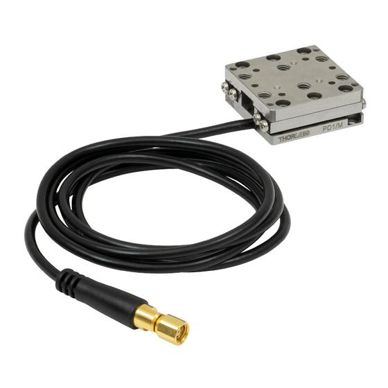
The PD1(/M) stage has a 20 mm travel range and open loop operation. When driven by the KIM101 Inertial Piezo Controller, the PD1(/M) stage offers continuous long term stepping as well as periodic position and hold mode with 3 N clamping/holding force. -
Page 7: Unpacking
Unpack the stage with care. Check the contents for signs of damage. If there is any sign of damage or missing parts, contact Thorlabs immediately. The lock plate and corresponding M1.4 screws are used to lock the stage during transportation or storage. -
Page 8: Chapter 4 Installation
Mount the PD1(/M) stage on an even surface. The recommended flatness of the surface is ≤5 μm. For applications with large temperature changes, only mount the PD1(/M) stage on a surface that has the same or similar thermal expansion properties as the stage. - Page 9 PD1 Piezo Inertia Drive Stage Chapter 4: Installation Thorlabs offers a mounting baseplate, PD1B(/M), to provide a flat surface for mounting and 1.00" (25.0 mm) long #8 (M4) counterbored slot for attaching to table. 1. Firstly mount the PD1B(/M) to a breadboard or base plate or table using two 8-32 (M4) cap screws via 1.00"...
-
Page 10: Setting Up An Xy & Xyz Stage Configuration
PD1 Piezo Inertia Drive Stage Chapter 4: Installation 4.1.2. Setting Up an XY & XYZ Stage Configuration CAUTION In a multi-axis system, upper stage(s) and any mounting adapters must also be moved and should be considered as part of the load. - Page 11 PD1 Piezo Inertia Drive Stage Chapter 4: Installation To set up an XYZ-axis system, firstly build the XY-axis system as above and then use an adapter plate. Thorlabs offers a right-angle bracket adapter plate, PD1Z(/M), to mount the PD series stage vertically.
-
Page 12: Mounting Components To The Stage
Thorlabs offers a thin mounting adapter plate, PD1T(/M), to provide a convenient means of attaching load to the PD series stages by a central 8-32(M4) tapped hole and other 4-40(M2 & M3) tapped holes. Both the imperial and metric versions have four 4-40 tapped holes spaced for 16 mm cage systems. - Page 13 Figure 8 Mounting Adapter PD1U(/M) on Moving Platform Thorlabs also offers a thick mounting adapter plate, PD1U(/M), to provide a convenient means of attaching load to the PD series stages by five #8 (M4) counterbores. As shown in Figure 8: 1.
- Page 14 PD1 Piezo Inertia Drive Stage Chapter 4: Installation #8 (M4) Counterbores 2-56 (M2) Cap Screw, 8 mm Long Ø2 mm Dowel Pin, 3 mm Long Figure 9 Mounting Adapter PD1U(/M) on Moving Platform Page 12 CTN013949-D02...
-
Page 15: Electrical Connections
TIM101 controller is not compatible. The stage is shipped with a 1 m (3.3 ft) cable that is terminated in an SMC connector. Connect the PD1(/M) stage to one of the MOT (motor) terminals on the rear panel of the KIM101 controller - see the KIM101 controller manual for pin out details. -
Page 16: Chapter 5 Operation
– see the manual supplied with the KIM101 controller, and the help file supplied with the software for more information. NOTE The PD1(/M) stage is an open loop device that has been designed to offer relative positioning which can be commanded via the number of steps. CAUTION If the stage is driven to the end of its travel range, do not drive it further. -
Page 17: Maintenance
Periodic maintenance helps to ensure the optimum stepping performance during its lifetime. NOTE The PD1(/M) stage is assembled with rust preventative oil. Don’t wipe the stage with organic solvent. When necessary, clean the surfaces of the stage with a dry, dust-free cloth. -
Page 18: Chapter 6 Specifications
PD1 Piezo Inertia Drive Stage Chapter 6: Specifications Chapter 6 Specifications Item # PD1(/M) Travel Range 20 mm (0.78") Typical Step Size 1 μm Maximum Step Size <3 μm Step Size Adjustability Up to 30% Maximum Step Frequency 2 kHz... -
Page 19: Chapter 7 Frequently Asked Questions
What driver can I use? The PD1(/M) stage must be driven by a Thorlabs KIM101 controller version must be 2019 or newer (per the S/N label) with a firmware revision of 010003 or higher (indicated when the controller is powered on). Earlier versions of the KIM101 controller or those with older firmware will not function properly and may cause failure of the stage and/or the controller. -
Page 20: Chapter 8 Mechanical Drawings
PD1 Piezo Inertia Drive Stage Chapter 8: Mechanical Drawings Chapter 8 Mechanical Drawings Figure 10 PD1 Imperial Stage Drawing Page 18 CTN013949-D02... - Page 21 PD1 Piezo Inertia Drive Stage Chapter 8: Mechanical Drawings Figure 11 PD1/M Metric Stage Drawing Rev C, February 9, 2021 Page 19...
-
Page 22: Chapter 9 Regulatory
Waste Treatment is Your Own Responsibility If you do not return an “end of life” unit to Thorlabs, you must hand it to a company specialized in waste recovery. Do not dispose of the unit in a litter bin or at a public waste disposal site. -
Page 23: Chapter 10 Declaration Of Conformity
PD1 Piezo Inertia Drive Stage Chapter 10: Declaration of Conformity Chapter 10 Declaration of Conformity Rev C, February 9, 2021 Page 21... -
Page 24: Chapter 11 Thorlabs Worldwide Contacts
PD1 Piezo Inertia Drive Stage Chapter 11: Thorlabs Worldwide Contacts Chapter 11 Thorlabs Worldwide Contacts For technical support or sales inquiries, please visit us at www.thorlabs.com/contact for our most up-to-date contact information. USA, Canada, and South America UK and Ireland Thorlabs, Inc. - Page 25 www.thorlabs.com...
Need help?
Do you have a question about the PD1 and is the answer not in the manual?
Questions and answers