Table of Contents
Advertisement
Quick Links
Advertisement
Table of Contents

Related Manuals for THORLABS KURIOS-WB1


Summary of Contents for THORLABS KURIOS-WB1
- Page 1 KURIOS ® Liquid Crystal Tunable Filters User Guide...
-
Page 3: Table Of Contents
Kurios ® Liquid Crystal Tunable Filters Table of Contents Chapter 1 Warning Symbol Definitions .................... 1 Chapter 2 Safety ............................ 2 Chapter 3 Description ........................... 3 3.1. Overview .......................... 3 3.1.1. Parts List – Accessories ......................3 3.2. Controls and Connections ..................... 5 3.2.1. - Page 4 6.9. Angle of Incidence (Field of View) ................26 Chapter 7 Specifications ........................27 7.1. Fixed Bandwidth Tunable Filters ................. 27 7.2. Selectable Bandwidth Tunable Filters ................. 27 7.3. Mechanical Drawings ....................28 Chapter 8 Certification and Compliances ..................31 Chapter 9 Regulatory ...........................33 Chapter 10 Thorlabs Worldwide Contacts ..................34 ...
-
Page 5: Chapter 1 Warning Symbol Definitions
Kurios ® Liquid Crystal Tunable Filters Chapter 1: Warning Symbol Definitions Chapter 1 Warning Symbol Definitions Below is a list of warning symbols you may encounter in this manual or on your device. Symbol Description Direct Current Alternating Current Both Direct and Alternating Current Earth Ground Terminal Protective Conductor Terminal Frame or Chassis Terminal... -
Page 6: Chapter 2 Safety
Kurios ® Liquid Crystal Tunable Filters Chapter 2: Safety Chapter 2 Safety All statements regarding safety of operation and technical data in this instruction manual will only apply when the unit is operated correctly. DO NOT OPEN HOUSING Except for the main fuse, which is accessible from the outside of the housing, KURIOS has no user- serviceable parts. -
Page 7: Chapter 3 Description
SM1 (1.035"-40) threaded. SM1-threaded adapters can be used to mount lens tubes, filters, and other optics on the head. In addition, these optical heads are compatible with Thorlabs’ 30 mm cage system. It can also be post mounted using the 8-32 (M4) tapped holes located on the sides of the filter housing. - Page 8 Kurios ® Liquid Crystal Tunable Filters Chapter 3: Description SM1CP2 SM2EC2 KURIOS-WB1(/M) KURIOS-WL1(/M) KURIOS-VB1(/M) KURIOS-XL1(/M) KURIOS-XE2(/M) Figure 3 Aluminum Case for Filter Head Figure 4 Cover for Clear Apertures Figure 5 USB, Connection, and Power Cables Figure 6 Test Report 1’’...
-
Page 9: Controls And Connections
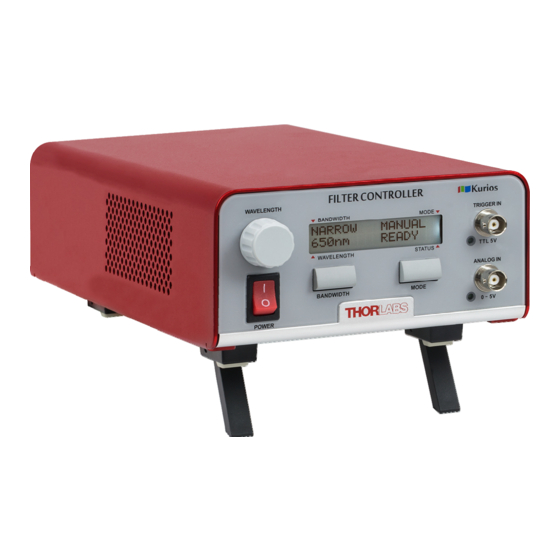
WAVELENGTH: Adjust the passband wavelength in MANUAL mode. BANDWIDTH: KURIOS-WB1(/M): Toggle between WIDE and BLACK (beam blocking) modes. KURIOS-WL1(/M): Toggle between WIDE and BLACK (beam blocking) modes. KURIOS-XL1(/M): Toggle between NARROW and BLACK (beam blocking) modes. KURIOS-XE2(/M): Toggle between NARROW and BLACK (beam blocking) modes. - Page 10 Kurios ® Liquid Crystal Tunable Filters Chapter 3: Description Status Display BANDWIDTH: WIDE: filter works at wide bandwidth mode. (Default filter operation after power on for WB1/VB1/WL1 filters) MEDIUM: filter works at medium bandwidth mode. NARROW: filter works at narrow bandwidth mode. (Default filter operation mode for XE2/XL1 filters) BLACK: Beam blocking mode, minimum transmission.
-
Page 11: Kurios Controller Back Panel
Kurios ® Liquid Crystal Tunable Filters Chapter 3: Description 3.2.2. KURIOS Controller Back Panel Figure 10 KURIOS Back Panel OPTICAL HEAD: Connects to the optical head of the filter. This should be connected before the controller is turned on. If the cable is not connected while the power is on, then the controller must be restarted. -
Page 12: Kurios Optical Head
Kurios ® Liquid Crystal Tunable Filters Chapter 3: Description 3.2.3. KURIOS Optical Head Figure 12 KURIOS Optical Head All KURIOS optical heads have a similar appearance, but different KURIOS models have different path thicknesses, clear aperature, and threads. Connector: Connects to the optical head connector on the KURIOS controller. Status LED: Red: Filter warming up to 40°C. -
Page 13: Chapter 4 Installation
SM1(1.035"-40) internal threads, which are used for mounting Thorlabs’ 30 mm cage systems and lens tubes, respectively. The optical head and faces of KURIOS-WL1(/M) and KURIOS-XL1(/M) have four 4-40 internal threads, which are compatible with Thorlabs’ 60 mm cage systems, as well as SM2(2.035"-40) interal threads for lens tube mounting. - Page 14 Kurios ® Liquid Crystal Tunable Filters Chapter 4: Installation Figure 13 KURIOS Optical Head With A Premium Shortpass Filter All KURIOS tunable filter heads have three 8-32 (M4) tapped holes for post mounting. The field of view of the optical head is ±6° and therefore it is best to pass a well collimated beam into the filter for optimal performance.
-
Page 15: Chapter 5 Operation
5.1.1. Bandwidth KURIOS has four bandwidth modes: WIDE, MEDIUM, NARROW, and BLACK. Pressing the bandwidth button on the controller cycles through the modes in the following order: KURIOS-WB1(/M) : WIDE, BLACK. KURIOS-WL1(/M) : WIDE, BLACK. KURIOS-XE2(/M) : NARROW, BLACK. KURIOS-XL1(/M) : NARROW, BLACK. -
Page 16: Sequenced
Kurios ® Liquid Crystal Tunable Filters Chapter 5: Operation This unit must not be operated in explosive environments. Additionally, this unit should not be used in wet/damp conditions. Do not obstruct the air ventilation slots in the housing! 5.1.3. Sequenced In SEQUENCED mode, the KURIOS stores a set of passband wavelengths and it issues the wavelengths to the optical head whenever a trigger is received. -
Page 17: Software Gui
LabVIEW VIs can be utilized. Full documentation on the available commands is provided in the SDK manual. Figure 14 Software GUI Main Window 5.2.1. Product ID Indicating the product ID while a KURIOS product is connected: Thorlabs Kurios-xxx SN-xxxxxxx HWxx FWxx CN-xxxxxxx Page 13 Rev G, September 3, 2019... -
Page 18: Main Menu
For technical support, Microsoft Outlook launches (if installed) and directly addresses to techsupport@thorlabs.com. About Displays the detailed information about the KURIOS software. Please have these details available when contacting Thorlabs Technical Support. Help Opens the KURIOS software help documentation. Page 14... -
Page 19: Operation / Control Mode
External trigger in time. Bandwidth Mode Figure 18 Software Bandwidth Mode Different version of KURIOS tunable filter has different bandwidth mode available. KURIOS-WB1(/M),KURIOS-WL1(/M) : WIDE, BLACK KURIOS-VB1(/M): WIDE, MEDIUM, NARROW, BLACK KURIOS-XE2(/M), KURIOS-XL1(/M): NARROW, BLACK Wavelength Figure 19 Software Wavelength The wavelength bar indicates the current wavelength setting. - Page 20 Sequence Table Figure 21 Software Sequence Table Different versions of the tunable filter have different setting sequence formats in the sequence table. KURIOS-WB1(/M),KURIOS-WL1(/M), KURIOS-XE2(/M), KURIOS-XL1(/M): Sequence, wavelength (nm), Interval (ms). KURIOS-VB1(/M): Sequence, wavelength (nm), Interval (ms), Bandwidth Mode. Page 16...
-
Page 21: Command Line
Kurios ® Liquid Crystal Tunable Filters Chapter 5: Operation By right clicking on the table, basic operations are shown. 5.3. Command Line The KURIOS can be controlled by a command line through the USB port, as a virtual COM or RS-232 device. This is offered to enable operation through a terminal interface or for those who wish to write their own program to control the unit. - Page 22 Kurios ® Liquid Crystal Tunable Filters Chapter 5: Operation Command Syntax Description *idn? or Returns the model number, hardware and firmware versions Get ID *IDN? Returns connected filter's wavelength range Get Specification Returns two bytes integer (int 16), Top 8 bits represents filter spectrum; 0000 0001 = Visible 0000 0010 = NIR Bottom 8 bits represents available bandwidth mode:...
-
Page 23: Description Of Commands
5.4.1. *idn? or *IDN?– Hardware Information Queries the optical head model, controller hardware and firmware versions. Return: THORLABS KURIOS-VB1 SN-xxxxxxxx HWx.x FWx.x CN-xxxxxxxx where SN is optical head serial numbers; HW is controller hardware version; FW is firmware version; CN is the controller serial number. -
Page 24: Om=N; Om? - Operation Mode
5.4.5. BW=n; BW? – Bandwidth Mode The BW command is used to set or query the bandwidth mode of the filter. KURIOS-WB1(M) and KURIOS-WL1(M) optical heads have two bandwidth modes available: WIDE and BLACK. KURIOS-VB1(M) optical head has four bandwidth modes available: WIDE, MEDIUM, NARROW and BLACK. -
Page 25: Wl=N; Wl? - Passband Wavelength
KURIOS-WB1(/M): valid values SS=n1 n2 n3. n4 is not given, then it is set to the default value n4=2 (WIDE). KURIOS-WL1(/M): valid values SS=n1 n2 n3. n4 is not given, then it is set to the default value n4=2 (WIDE). -
Page 26: Is=N1 N2 N3 N4; Is=N1 N2 - Insert Into Sequence
Kurios ® Liquid Crystal Tunable Filters Chapter 5: Operation Queries the wavelength and time interval of the entire sequence list. SS1=n12 n13 n14 SS2=n22 n23 n24 SS3=n32 n33 n34 If the sequence has not been initialized for the first time, or has been deleted, then SS? returns the following: SS=0 NOTE: When setting sequence items using the SS command which is greater than the existing sequence list length, the controller automatically fills in the intermediate values with a default wavelength of 550 nm for VIS tunable filter... -
Page 27: Wd=N; Wd? - Default Wavelength For All Elements In Sequences
The BD command is used to set or query the default Bandwidth Mode for all elements in sequence.This command is only available for KURIOS-VB1(/M). The default Bandwidth Mode for KURIOS-WL1(/M) and KURIOS-WB1(/M) is WIDE. The default Bandwidth Mode for KURIOS-XE2(/M) and KURIOS-XL1(/M) is NARROW. -
Page 28: St? - Filter Status
Kurios ® Liquid Crystal Tunable Filters Chapter 5: Operation 5.4.14. ST? – Filter Status Queries the current status of the optical head. Return: ST=n where n can be one of the following: n=0: Initialization. The filter is in an initialization stage to transit from idle to operation state. This initialization period takes 90sec from power up. -
Page 29: Chapter 6 Technical Terminology
Technical Terminology 6.1. Bandwidth Thorlabs’ KURIOS ® tunable filter defines the passband bandwidth as the Full Width at Half Maximum (FWHM). This is the spectral width between the two points where the filter’s transmission reaches half of the peak value. The KURIOS filter’s bandwidths are dependent on wavelength and optical design, and therefore different models and... -
Page 30: Tuning Accuracy
Kurios ® Liquid Crystal Tunable Filters Chapter 6: Technical Terminology 6.7. Tuning Accuracy The difference between the wavelength setting and the actual filter output center wavelength is defined as tuning accuracy, and is measured in terms of FWHM at the current set wavelength. KURIOS tunable filter output center wavelength accuracy is corrected to within ±FWHM/10. -
Page 31: Chapter 7 Specifications
Liquid Crystal Tunable Filters Chapter 7: Specifications Chapter 7 Specifications 7.1. Fixed Bandwidth Tunable Filters Specification Value Item # KURIOS-WB1(/M) KURIOS-WL1(/M) KURIOS-XL1(/M) KURIOS-XE2(/M) Center Wavelength 420 - 730 nm 430 - 730 nm 650 - 1100 nm Bandwidth (FWHM) 35 nm at 550 nm... -
Page 32: Mechanical Drawings
Mechanical Drawings Figure 24 KURIOS-WB1/M Optical Head Note: KURIOS-WB1 contains 8-32 tapped holes (in 3 places) instead of M4 tapped holes. Figure 25 KURIOS-VB1/M Optical Head Note: KURIOS-VB1 contains 8-32 tapped holes (in 3 places) instead of M4 tapped holes. - Page 33 Kurios ® Liquid Crystal Tunable Filters Chapter 7: Specifications Figure 26 KURIOS-WL1/M Optical Head Note: KURIOS-WL1 contains 8-32 tapped holes (in 3 places) instead of M4 tapped holes. Figure 27 KURIOS-XE2/M Optical Head Note: KURIOS-XE2 contains 8-32 tapped holes (in 3 places) instead of M4 tapped holes. Page 29 Rev G, September 3, 2019...
- Page 34 Kurios ® Liquid Crystal Tunable Filters Chapter 7: Specifications Figure 28 KURIOS-XL1 Optical Head Note: KURIOS-XL1/M contains M4 tapped holes (in 3 places) instead of 8-32 tapped holes. Figure 29 Controller for All KURIOS Liquid Crystal Tunable Filters Page 30 CTN002811-D03...
-
Page 35: Chapter 8 Certification And Compliances
Kurios ® Liquid Crystal Tunable Filters Chapter 8: Certification and Compliances Chapter 8 Certification and Compliances Page 31 Rev G, September 3, 2019... - Page 36 Kurios ® Liquid Crystal Tunable Filters Chapter 8: Certification and Compliances Page 32 CTN002811-D03...
-
Page 37: Chapter 9 Regulatory
Waste Treatment is Your Own Responsibility If you do not return an “end of life” unit to Thorlabs, you must hand it to a company specialized in waste recovery. Do not dispose of the unit in a litter bin or at a public waste disposal site. -
Page 38: Chapter 10 Thorlabs Worldwide Contacts
Liquid Crystal Tunable Filters Chapter 10: Thorlabs Worldwide Contacts Chapter 10 Thorlabs Worldwide Contacts For technical support or sales inquiries, please visit us at www.thorlabs.com/contact for our most up-to- date contact information. USA, Canada, and South America UK and Ireland Thorlabs, Inc. - Page 39 www.thorlabs.com...
Need help?
Do you have a question about the KURIOS-WB1 and is the answer not in the manual?
Questions and answers