Table of Contents
Advertisement
Advertisement
Table of Contents

Related Manuals for THORLABS MFF101


Summary of Contents for THORLABS MFF101
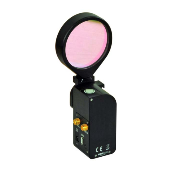
- Page 1 MFF101 and MFF102 Motorized Filter Flippers User Guide Original Instructions...
-
Page 2: Table Of Contents
5.3 Using the Software Commands ............16 Chapter 6 Software Reference ..............17 6.1 Introduction ...................17 6.2 GUI Panel .....................17 6.3 Settings Panel ..................18 Appendices Appendix A Preventive Maintenance ............21 Appendix B Specifications ................22 Appendix C Regulatory ................23 Appendix D Thorlabs Worldwide Contacts ..........25... -
Page 3: Chapter 1 Safety
Chapter 1 Safety 1.1 Safety Information For the continuing safety of the operators of this equipment, and the protection of the equipment itself, the operator should take note of the Warnings, Cautions and Notes throughout this handbook and, where visible, on the product itself. The following safety symbols may be used throughout the handbook and on the equipment itself. -
Page 4: Chapter 2 Overview
This small (70 mm x 30 mm x 30 mm) unit is powered by the included 15V power supply. It is shipped with a 1.5 m (59.0”) USB cable. The MFF101(/M) is supplied complete with our LMR1 (/M) Ø1" optics mount, while the MFF102 is shipped with the LMR2(/M). Other holders in the LMR range are compatible, up to a maximum diameter of 50.8 mm (2”). -
Page 5: Kinesis Software Overview
2.2 Kinesis Software Overview 2.2.1 Introduction The MFF series Filter Flippers share all the benefits of the Thorlabs range of motor controllers. This includes USB connectivity (allowing multiple units to be used together on a single PC), fully featured Graphical User Interface (GUI) panels, and extensive software function libraries for custom application development. - Page 6 Chapter 2 2.2.2 Kinesis Server Kinesis controls are re-usable compiled software components that supply both a graphical user interface and a programmable interface. With the Kinesis system, .Net Controls are deployed to allow direct control over (and also reflect the status of) the range of electronic controller units, including the MFF series filter flippers.
- Page 7 Kinesis Controls collection. This is available either by pressing the F1 key when running the Kinesis server, or via the Start menu, Start\Programs\Thorlabs\Kinesis\Kinesis Help. 2.2.3 Software Upgrades Thorlabs operate a policy of continuous product development and may issue software upgrades as necessary.
-
Page 8: Chapter 3 Mechanical Installation
Chapter 3 Mechanical Installation 3.1 Unpacking Note Retain the packing in which the unit was shipped, for use in future transportation. Caution Once removed from its packaging, the filter flipper is easily damaged by mishandling. The unit should only be handled by its base. 3.2 Environmental Conditions Warning Operation outside the following environmental limits may adversely... -
Page 9: Transportation
MFF101 and MFF102 Motorized Filter Flippers 3.3.2 Mounting the Unit to the Work Surface The filter flipper is normally used mounted to standard post via the 8-32 (M4) hole in the base, as shown in Fig. 3.1.. . 8-32 (M4) -
Page 10: Dimensions
Chapter 3 3.5 Dimensions POS 1 107.4mm (4.23in) 92.2mm POS 2 (3.63in) 90° Travel 50.0mm (1.97in) 42.2mm (1.66in) MFF101 57.4mm (2.26in) POS 1 27.9mm (1.10in) 132.5 mm (5.21 in) 104.5 mm POS 2 (4.11 in) 90° Travel 50.0 mm (1.97 in) 54.5 mm... -
Page 11: Changing The Lens Mount
MFF101 and MFF102 Motorized Filter Flippers 3.6 Changing The Lens Mount The mount is supplied complete with our LMR1(/M) 1" or LMR2(/M) 2” optical lens holder, but is compatible with other holders in the LMR range. Please note that the maximum load of 120g is based on using 2 x 2”... -
Page 12: Chapter 4 Software & Electrical Installation
If you experience any problems when installing software, contact Thorlabs on +44 (0)1353 654440 and ask for Technical Support. DO NOT CONNECT THE STAGE TO YOUR PC YET 1) Download the software from www.thorlabs.com. -
Page 13: Connecting The Hardware
MFF101 and MFF102 Motorized Filter Flippers 4.3 Connecting The Hardware 1) Perform the mechanical installation as detailed in Section 3. 2) Install the Kinesis Software - see Section 4.1. 3) Using the USB cable supplied, connect the stage unit to your PC. -
Page 14: Chapter 5 Operation
Chapter 5 Operation Warning When the unit is powered up, do not move the flipper arm by hand. 5.1 Manual Operation The Filter Flipper offers a fully featured motion control capability including Transit Time and I/O Configuration. When the unit is connected to the PC, these parameters are automatically set to allow “out of the box”... - Page 15 MFF101 and MFF102 Motorized Filter Flippers 5.2.2 Master/Slave Operation If required, two flipper units can be wired in a master/slave configuration, such that a demanded flip on one unit, also triggers the other unit to flip. 1) From the GUI panel of the Master unit, click the Settings button to display the settings panel.
-
Page 16: Using The Software Commands
Chapter 5 3) From the GUI panel of the Slave unit, click the Settings button to display the settings panel. 4) Make parameter settings as follows: Digital I/O Pin 1 Operating Mode: Input: Toggle Position Input Signal Mode: Logic Edge Input These settings set the Slave unit to flip the optic position, each time a Logic High (5V) Edge is received on DIG I/O 1. -
Page 17: Chapter 6 Software Reference
Chapter 6 Software Reference 6.1 Introduction This chapter gives an explanation of the parameters and settings accessed from the software running on a PC. 6.2 GUI Panel The following screen shot shows the graphical user interface (GUI) displayed when accessing the filter flipper using the Kinesis software. Fig. -
Page 18: Settings Panel
Chapter 6 Toggle - used to toggle between position 1 and position 2. When the button is clicked, the flipper is driven to the position at the speed entered in the ‘Transition Time’ field in the 'Settings' panel (see Section 6.3.). When at position, the LED in the associated button is lit. Settings button - Displays the 'Settings' panel, which allows the operating parameters to be entered - see Section 6.3. - Page 19 MFF101 and MFF102 Motorized Filter Flippers use in absence of a PC. To save the settings to hardware, check the ‘Persist Settings to the Device’ checkbox before clicking the ‘OK button. Caution The ‘Persist Settings’ functionality is provided to simplify use of the unit in the absence of a PC.
- Page 20 Chapter 6 Output: At Position - Sets IO connector to output mode, where the O/P signal indicates the flipper is ‘at position’. Output: In Motion - Sets IO connector to output mode, where the O/P signal indicates the flipper is in motion (i.e. between positions). Input Signal Mode - This parameter specifies the functionality of the input/output signal.
-
Page 21: Appendix A Preventive Maintenance
After the obstruction is removed, the unit should first be disabled to clear any fault codes, then re-enabled. In the event of a breakdown, or malfunction of the product please contact Thorlabs Tech Support. Contact details are contained in Chapter 4 . -
Page 22: Appendix B Specifications
Appendix B Specifications Parameter Value Travel 90° 500 ms to 2800 ms Flip Time Optic Diameter MFF101: 1” MFF102: 2” Flip to Flip Repeatability 50 µrad Angular Repeatability 240 µrad 120 g (4.23 oz) Max Load Max Torque 0.1 Nm... -
Page 23: Appendix C Regulatory
Appendix C Regulatory C.1 Declarations Of Conformity C.1.1 For Customers in Europe See Section C.2. C.1.2 For Customers In The USA This equipment has been tested and found to comply with the limits for a Class A digital device, persuant to part 15 of the FCC rules. These limits are designed to provide reasonable protection against harmful interference when the equipment is operated in a commercial environment. - Page 24 C.2 CE Certificate...
-
Page 25: Appendix D Thorlabs Worldwide Contacts
Waste treatment is your own responsibility. "End of life" units must be returned to Thorlabs or handed to a company specializing in waste recovery. Do not dispose of the unit in a litter bin or at a public waste disposal site. - Page 26 www.thorlabs.com...
Need help?
Do you have a question about the MFF101 and is the answer not in the manual?
Questions and answers