LOVATO ELECTRIC ATL600 Instruction Manual
Automatic transfer switch controller
Hide thumbs
Also See for ATL600:
- Instruction manual (48 pages) ,
- Installation manual (14 pages) ,
- Instruction manual (33 pages)
Table of Contents
Advertisement
AVERTIZARE!
Citiţi cu atenţie manualul înainte de instalare sau utilizare.
Acest echipament va fi instalat de personal calificat, în conformitate cu
standardele actuale, pentru a evita deteriorări sau pericolele.
● Înainte de efectuarea oricărei operaţiuni de întreţinere asupra dispozitivului, îndepărtaţi toate
tensiunile de la intrările de măsurare şi de alimentare.
● Produsele ilustrate în prezentul sunt supuse modificărilor şi schimbărilor fără notificare
anterioară.
● Datele tehnice şi descrierile din documentaţie sunt precise, în măsura cunoştinţelor noastre,
dar nu se acceptă nicio răspundere pentru erorile, omiterile sau evenimentele neprevăzute care
apar ca urmare a acestora.
● Trebuie inclus un disjunctor în instalaţia electrică a clădirii. Acesta trebuie instalat aproape de
echipament şi într-o zonă uşor accesibilă operatorului.
Trebuie marcat ca fiind dispozitivul de deconectare al echipamentului:
IEC/EN 61010-1 § 6.12.2.1.
● Curăţaţi instrumentul cu un material textil moale şi uscat; nu utilizaţi substanţe abrazive,
detergenţi lichizi sau solvenţi
.
Index
tabletei dvs.
Doc: I414ROGB11_14.doc
ATL600 - ATL610
CONTROLER COMUTATOR
CU TRANSFER AUTOMAT
MANUAL DE UTILIZARE
Pagina
2
2
3
3
3
4
4
5
5
7
8
8
8
9
9
9
10
10
11
11
11
12
13
20
20
20
21
21
22
23
24
25
30
30
30
32
RO
ATL600 - ATL610
AUTOMATIC TRANSFER
SWITCH CONTROLLER
INSTRUCTIONS MANUAL
WARNING!
Carefully read the manual before the installation or use.
This equipment is to be installed by qualified personnel, complying to
current standards, to avoid damages or safety hazards.
● Before any maintenance operation on the device, remove all the voltages from measuring and
supply inputs.
● Products illustrated herein are subject to alteration and changes without prior notice.
● Technical data and descriptions in the documentation are accurate, to the best of our
knowledge, but no liabilities for errors, omissions or contingencies arising there from are
accepted.
● A circuit breaker must be included in the electrical installation of the building. It must be
installed close by the equipment and within easy reach of the operator.
It must be marked as the disconnecting device of the equipment:
IEC /EN 61010-1 § 6.12.2.1.
● Clean the instrument with a soft dry cloth; do not use abrasives, liquid detergents or solvents
Index
10/10/2014
GB
.
Page
2
2
3
3
3
4
4
5
5
7
8
8
8
9
9
9
10
10
11
11
11
12
13
20
20
20
21
21
22
23
24
25
30
30
30
32
p. 1 / 32
Advertisement
Table of Contents

Related Manuals for LOVATO ELECTRIC ATL600


Summary of Contents for LOVATO ELECTRIC ATL600
-
Page 1: Table Of Contents
ATL600 - ATL610 ATL600 - ATL610 CONTROLER COMUTATOR AUTOMATIC TRANSFER CU TRANSFER AUTOMAT SWITCH CONTROLLER MANUAL DE UTILIZARE INSTRUCTIONS MANUAL AVERTIZARE! WARNING! Citiţi cu atenţie manualul înainte de instalare sau utilizare. Carefully read the manual before the installation or use. -
Page 2: Introducere
Introducere Introduction Unitățile de control ATL600 și ATL610 au fost proiectate pentru a oferi The ATL600 and ATL610 control units have been designed to offer state- funcții de ultimă generaţie pentru aplicațiile de comutare cu transfer of-the-art functions for automatic transfer switching applications between automat între două... -
Page 3: Funcţii Butoane Frontale
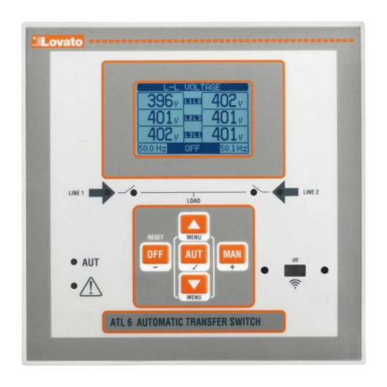
Funcţii butoane frontale Front buttons functions Buton OPRIT - Selectează modul de operare OPRIT. OFF button - Selects the OFF operating mode. Buton AUT- Selectează modul de operare automat. Lumini LED AUT AUT button - Selects the automatic mode. Green AUT LED lights. verzi. -
Page 4: Pornire
Pornire Power-up ATL600 are alimentare de 100 - 240 V c.a. ATL600 has 100-240VAC supply. ATL610 are alimentare de 100 - 240 V c.a. sau 12 - 24 V c.c. În cazul ATL610 has 100-240VAC or 12-24VDC supply. In the case of the prezenței simultane a ambelor surse de alimentare, se acordă... -
Page 5: Parolă De Acces
Parolă de acces Password access Parola este utilizată pentru a permite sau bloca accesul la meniul de The password is used to enable or lock the access to setting menu setare (configurare) și la meniul de comenzi. (setup) and to commands menu. ... - Page 6 Date statistice Statistics Line 2 Linia1 Linia 2 Contor MAN mode Line1 AUT mode Contor commutation comutare comutare commutation counter mod MAN mod AUT counter Time lapse Interval de Alarmă contor Alarms with load timp cu counter A03 A03 A04 sarcină...
-
Page 7: Extensibilitate
Listă evenimente Event List Event code eveniment Descriere Description eveniment of event Notă: Unele dintre paginile enumerate mai sus pot să nu fie afișate dacă Note: Some of the pages listed above may not be displayed if the funcția relevantă este dezactivată. De exemplu, în cazul în care funcția relevant function is disabled. -
Page 8: Canale De Comunicare
Următorul tabel grupează toate I/O și variabilele interne gestionate de The following table groups all the I/O and the internal variables managed ATL600, cu evidențierea intervalului acestora (număr variabile per tip). by the ATL600, with highlighting of their range (variables number per type). COD. -
Page 9: Praguri Limită (Limx)
Starea variabilei limită variable Variabile controlate de la distanţă (REMx) Remote-controlled variables (REMx) ATL600 şi ATL610 pot gestiona până la 8 variabile controlate de la ATL600 and ATL610 can manage up to 8 remote-controlled variables distanţă (REM1 ... REM8). (REM1…REM8). -
Page 10: Test Automat
Pentru fiecare alarmă, utilizatorul poate defini un mesaj gratuit care va For every alarm, the user can define a free message that will appear on apărea pe pagina de alarmă. the alarm page. Proprietățile alarmelor utilizatorului pot fi definite în același mod ca și ... -
Page 11: Setarea Parametrilor Prin Intermediul Pc-Ului
Acesta este izolat prin galvanizare de la circuitele interne ale ATL6, It is galvanically isolated from the internal circuits of the ATL6.., garantând astfel cel mai mare grad de siguranţă pentru operator. guaranteeing the greatest safety for the operator. Transfer de date la viteză ridicată. High speed data transfer. -
Page 12: Setarea Parametrilor (Configurare) Din Panoul Frontal
Selectaţi pictograma . Dacă este dezactivată (afișată cu gri), Select the icon . If it is disabled (displayed in grey) you must trebuie să introduceți parola (consultaţi capitolul Parolă de acces). enter the password (see chapter Password access). Apăsaţi pentru a deschide meniul de configurare. Press ... -
Page 13: Tabelul Parametrilor
Când este afișat ecranul de editare, setarea parametrilor poate fi When the editing screen is displayed, the parameter setting can be modificată cu tastele + şi - Ecranul arată noua configurație, o bară modified with + and - keys. The screen shows the new setting, a graphic grafică... - Page 14 M03 – PAROLĂ Implicit Interval M03 – PASSWORD Default Range P03.01 Activare cu parolă OFF-ON P03.01 Password enable OFF-ON P03.02 Parola pentru nivelul de utilizator 1000 0-9999 P03.02 User level password 1000 0-9999 P03.03 Parola pentru nivelul avansat 2000 0-9999 P03.03 Advanced level password 2000...
- Page 15 P05.06 – Dacă după trimiterea unei comenzi de deschidere sau închidere către un disjunctor, P05.06 – If, after sending an open or close command to a circuit breaker, this is not positioned acesta nu este poziţionat corect în acest timp, sunt generate alarmele A03 şi A04. correctly within this time, alarms A03 or A04 are generated.
- Page 16 P06.13 Limită frecvenţă MAX 100-120/OFF P06.16 MIN frequency delay 0-600 P06.14 Întârziere frecvenţă MAX 0-600 P06.17 LINE 1 control OFF mode P06.15 Limită frecvenţă MIN OFF/80-100 OFF+GLOB P06.16 Întârziere frecvenţă MIN 0-600 ON+GLOB P06.17 Mod OPRIT control LINIE 1 P06.18 LINE 1 control MAN mode OFF+GLOB OFF+GLOB...
- Page 17 M08 – COMUNICAŢIE M8 – COMMUNICATION Default Range Implicit Interval (COMn, n=1…2) (COMn, n=1…2) P08.n.01 Adresă serială nod 01-255 P08.n.01 Node serial address 01-255 P08.n.02 Viteză port serial 1200 P08.n.02 Serial port speed 1200 2400 2400 4800 4800 9600 9600 9600 9600 19200...
- Page 18 M10 – INTRĂRI PROGRAMABILE Implicit Interval M10 – PROGRAMMABLE INPUTS Default Range (INPn, n=1…14) (INPn, n=1…14) P10.n.01 Funcţie intrare INPn (diverse) (consultaţi P10.n.01 INPn input function (various) (see Input tabelul Funcții functions de intrare) table) P10.n.02 Index funcții (x) OFF / 1…99 P10.n.02 Function index (x) OFF / 1…99 P10.n.03 Tip contact...
- Page 19 P13.05 şi P13.06 – Defineşte pragul superior, obținut prin înmulțirea valorii P13.n.03 cu P13.05 and P13.06 – Define the upper threshold, obtained by multiplying value P13.n.03 by P13.n.04. P13.n.04. P13.07 – Întârziere intervenție prag superior. P13.07 – Upper threshold intervention delay. P13.08, P13.09, P13.10 –...
-
Page 20: Alarme
Dacă alarma nu poate fi resetată, problema care a generat alarma If the alarm cannot be reset, the problem that generated the alarm must trebuie încă să fie rezolvată. still be solved. În cazul uneia sau mai multor alarme, comportamentul ATL6 depinde de ... -
Page 21: Tabel Funcţie Intrare Programabilă
Secvenţă fază Secvența de fază înregistrată pe LINIA 2 nu corespunde cu The load has been without power for a time longer than the greşită Linia 2 cea programată. Load not powered maximum specified with P05.11, either because both source timeout lines were absent or because both the breakers remained Sarcina a fost deconectată... -
Page 22: Tabel Funcţie Ieşire
Urgenţă Contact NC care, dacă este deschis, cauzează deschiderea Emergency NC contact which, if open, causes both circuit breakers to ambelor disjunctoare şi generează alarma A09 open and generates alarm A09 Generator pregătit 1 Atunci când este închis semnalează faptul că generatorul conectat la linia 1 este disponibil pentru utilizare. -
Page 23: Meniul Comenzilor
Alarmă globală Ieșire activată în prezența oricărei alarme cu proprietatea Line 1 status Output energized when there are all conditions to be able Alarmă globală activată to connect the load to the line 1 Stare linie 1 Ieşire sub tensiune atunci când există toate condiţiile Line 2 status Output energized when there are all conditions to be able pentru a permite conectarea sarcinii la linia 1... -
Page 24: Instalare
Instalare Installation ATL600 este conceput pentru instalare încastrată. Cu montarea corectă, ATL600 is designed for flush-mount installation. With proper mounting, it garantează cu protecția frontală a garniturii IP65 opţionale. guarantees with the optional gasket IP65 front protection. Introduceţi dispozitivul în orificiul din panoul frontal, asigurându-vă că... -
Page 25: Scheme Electrice
Scheme electrice Wiring diagrams Controlul disjunctoarelor motorizate Control of motorised circuit breakers LINE 1 LINE 2 LINE 1 ATL600 LINE 2 LINE 1 LINE 2 SUPPLY SUPPLY DIGITAL INPUTS DUAL POWER SUPPLY L2 L3 N LOAD Setarea parametrilor pentru schema de conexiuni din imagine Parameter setting for the wiring diagram in picture Bornă... - Page 26 Controlul comutatorului cu comutare motorizată Control of motorized changeover switch LINE 1 LINE 2 LINE 1 ATL600 LINE 2 LINE 1 LINE 2 SUPPLY SUPPLY DIGITAL INPUTS DUAL POWER SUPPLY L2 L3 N LOAD Setarea parametrilor pentru schema de conexiuni din imagine Parameter setting for the wiring diagram in picture Bornă...
- Page 27 Controlul contactoarelor Control of contactors LINE 1 LINE 2 L3 N LINE 1 ATL600 LINE 2 LINE 1 LINE 2 SUPPLY SUPPLY DIGITAL INPUTS LOAD DUAL POWER SUPPLY Setarea parametrilor pentru schema de conexiuni din imagine Parameter setting for the wiring diagram in picture Bornă...
- Page 28 Punere în aplicare sursă de alimentare dublă cu control de tensiune Dual power supply implementation with auxiliary voltage control by auxiliară prin sursă de alimentare dublă Lovato Electric cod releu Lovato Electric dual power supply relay code ATLDPS1 ATLDPS1 ATLDPS1 ALARM Punere în aplicare sursă...
- Page 29 Linie 2 venind de la generator Line 2 coming from generator Control tensiune auxiliară prin ATL600 + alimentare duală c.a. opţională Auxiliary voltage control by ATL600 + optional AC Dual Power Supply (indisponibilă alimentarea cu baterie) (battery supply not available)
-
Page 30: Poziţia Bornelor
Poziţia bornelor Terminals position OUT1 - OUT7 B300 / 250V~ 8A AC1 / 1A 30V= PILOT DUTY ATL610 ONLY Dimensiunile mecanice şi decuparea în panoul frontal (mm) Mechanical dimensions and front panel cut-out (mm) Doc: I414ROGB11_14.doc 10/10/2014 p. 30 / 32... -
Page 31: Caracteristici Tehnice
Caracteristici tehnice Technical characteristics Alimentare c.a.: borne 13, 14 AC Supply : terminals 13, 14 100 - 240 V~ 100 - 240V~ Tensiune nominală Us Rated voltage Us 110 - 250 V= 110 - 250V= 90 - 264 V~ 90 - 264V~ Interval tensiune de operare Operating voltage range 93,5 - 300 V=... -
Page 32: Istoric De Revizii Ale Manualului
Tensiune izolaţie Insulation voltage Alimentare cu energie electrică c.a. AC Supply Tensiune nominală izolaţie Ui 250 V~ Rated insulation voltage Ui 250V~ Tensiune nominală de rezistenţă la impuls Uimp 7,3 kV Rated impulse withstand voltage Uimp 7.3kV Tensiune de rezistenţă la frecvenţă putere 3 kV Power frequency withstand voltage Intrări tensiune Linia 1 şi Linia 2...
Need help?
Do you have a question about the ATL600 and is the answer not in the manual?
Questions and answers