Table of Contents
Advertisement
Quick Links
Introduction
This demonstration board allows the easy measurement of STCC50x1 parameters and the
evaluation of all its functions and operating modes.
Note:
The STCC2540 demonstration board is exactly the same, just assembled with the
STCC2540 instead of the STCC50x1 device. For details, please see
Features
USB 2.0 SDP or CDP data pass-through with S3 remote wakeup support or automatic
charging
Permanent USB 3.0 SuperSpeed data pass-through between input and output USB
connector
CDP mode with charging indication after CDP negotiation
DCP modes with charging indication (BC1.2 mode, divider mode, auto-detect mode)
Attach and charging/end-of-charging detection and indication
Resistor-programmable precise current limiter and short-circuit protection
June 2013
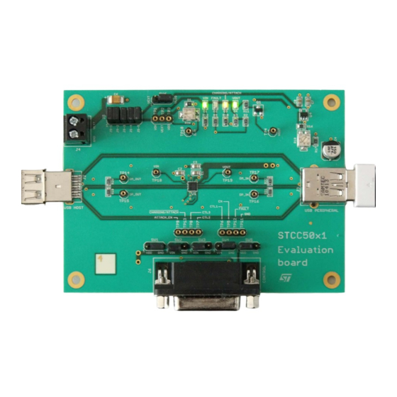
STCC50x1, STCC2540 demonstration board
Figure 1. STCC50x1 demonstration board
DocID023275 Rev 1
UM1551
User manual
Appendix
B.
www.st.com
1/17
Advertisement
Table of Contents

Related Manuals for ST STCC50x1


Summary of Contents for ST STCC50x1
- Page 1 User manual STCC50x1, STCC2540 demonstration board Introduction This demonstration board allows the easy measurement of STCC50x1 parameters and the evaluation of all its functions and operating modes. Note: The STCC2540 demonstration board is exactly the same, just assembled with the STCC2540 instead of the STCC50x1 device.
-
Page 2: Table Of Contents
Connectors............5 STCC2540 emulation using the STCC50x1 device ......6 Schematics diagram description . -
Page 3: Description
By default, the board is powered from a USB host (notebook, PC, docking station, etc.) through the J2 USB connector. No external power supply is necessary. In this mode, evaluation of all STCC50x1 device features is possible with the following limitation: Maximum charging current is limited by the USB host capabilities (typically 500 mA to 2000 mA). -
Page 4: Jumper Selectors
Description UM1551 Jumper selectors SW2 to SW4: operating mode (CTLx) 1 - 2 = 1, 2 - 3 = 0 (see Table Table 1. CTLx truth table Mode Note (CTL1) (CTL2) (CTL3) Power and data switch turned off Continuous V discharge No V discharge pulse on... -
Page 5: Jumper
If this connector is used, the jumper caps from SW1 to SW5 must be removed to allow remote setting of STCC50x1 inputs. No pull-up/pull-down resistors are provided on ATTACH_EN and CTLx inputs! On EN, an internal pull-down resistor of 250 k typ. is provided in the STCC50x1 device. DocID023275 Rev 1 5/17... -
Page 6: Stcc2540 Emulation Using The Stcc50X1 Device
CTL3 CHARGING/ATTACH FAULT Shield STCC2540 emulation using the STCC50x1 device This STCC50x1 device can be used also for evaluating the performance of the STCC2540 device using following settings: J5 = ON (V and V are powered from the same supply) ... -
Page 7: Auxiliary And Indication Circuits
LED current. Decoupling components The capacitors C1, C2, C3 and C4 are recommended decoupling components for the STCC50x1 device. They are recommended values, types and placements and can be used as a guide for application design. DocID023275 Rev 1... -
Page 8: Appendix A Schematic, Bom, And Layers
Appendix A Schematic, BOM, and layers Figure 2. Schematic of STCC50x1 demonstration board... - Page 9 Table 4. Bill of material Qty. Component Device Value Parts Manufacturer/supplier Ceramic capacitor M/16V/X7R/0805 1.0 µF C1, C2, C3, C7, C8 Murata Electrolytic capacitor EEEFK1A151P 150 µF Panasonic Tantalum capacitor M/16V/B 10 µF HSMG-C170 D1, D4 AVAGO Technologies HSMH-C170 AVAGO Technologies HSMY-C170 AVAGO Technologies USB3.0 connector...
- Page 10 Table 4. Bill of material (continued) Qty. Component Device Value Parts Manufacturer/supplier Pin header 1r x 3p SIL40PZ / 3 2.54 mm, straight, female (TP1-TP2-TP3) GM ELECTRONIC TP4, TP10, TP14, TP15, TP16, Pin header 1r x 1p SIL40PZ / 1 straight, female GM ELECTRONIC TP17, TP18, TP19 STCC5011,...
- Page 11 UM1551 Schematic, BOM, and layers Figure 3. Component layer Figure 4. Top layer DocID023275 Rev 1 11/17...
- Page 12 Schematic, BOM, and layers UM1551 Figure 5. Inner layer 1 Figure 6. Inner layer 2 12/17 DocID023275 Rev 1...
- Page 13 UM1551 Schematic, BOM, and layers Figure 7. Bottom layer Figure 8. Bottom layer (view from bottom side) DocID023275 Rev 1 13/17...
-
Page 14: Appendix Bstcc2540 Demonstration Board
This demonstration board allows easy measurement of STCC2540 parameters and evaluation of all its functions and operating modes. The STCC2540 device is simplified version of the STCC50x1 so the demonstration board is the same. In this section, only the differences between the STCC2540 and STCC5021 are described. -
Page 15: Jumper Selectors
UM1551 STCC2540 demonstration board Jumper selectors SW2 to SW4: operating mode (CTLx) 1 - 2 = 1, 2 - 3 = 0 (See Table Table 5. Truth table Mode Note (CTL1) (CTL3) (CTL2) Power and data switch turned off Continuous V discharge S0 SDP No V... -
Page 16: Revision History
Revision history UM1551 Table 6. J6 pinout Pin number Connection Pin number Connection Do not connect CTL1 CTL2 CTL3 Do not connect CHARGING Do not connect FAULT Shield Revision history Table 7. Document revision history Date Revision Changes 10-Jun-2013 Initial release. 16/17 DocID023275 Rev 1... - Page 17 No license, express or implied, by estoppel or otherwise, to any intellectual property rights is granted under this document. If any part of this document refers to any third party products or services it shall not be deemed a license grant by ST for the use of such third party products or services, or any intellectual property contained therein or considered as a warranty covering the use in any manner whatsoever of such third party products or services or any intellectual property contained therein.
Need help?
Do you have a question about the STCC50x1 and is the answer not in the manual?
Questions and answers