Table of Contents
Advertisement
Quick Links
UM2309
User manual
Getting started with the 45 W wall adapter solution for USB
Type-C Power Delivery
Introduction
This board has been physically tested and validated; it is not for sale.
This USB Power Delivery wall adapter is a USB-IF certified solution with a 45 W isolated power supply
with USB Power Delivery controller.
This USB Type-C PD wall power adapter design is for universal line voltage applications based on the
STCH02 Primary controller and STUSB4700 USB PD controller.
The 5 V, 9 V and 15 V USB output voltage profiles all have a 3 A rating.
The offline power supply is implemented in an isolated flyback topology based on the STCH02 quasi-
resonant controller with ultra-low standby power consumption. The USB Power Delivery (PD) is
managed by the STUSB4700 and is Type-C compatible: power negotiation, Vbus discharge,
protections, etc. are entirely managed by the IC.
The USB power supply architecture connects a power board with a controller board. This design
optimizes the form factor and lets you scale the power section up or down to suit different USB Power
Adapter applications.
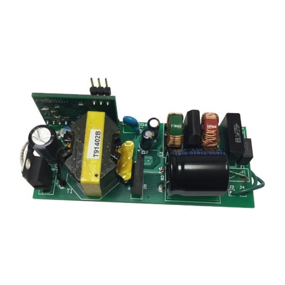
Figure 1: STEVAL-USBPD45H evaluation board
December 2017
DocID031190 Rev 1
1/33
www.st.com
Advertisement
Table of Contents

Related Manuals for ST STEVAL-USBPD45H


Summary of Contents for ST STEVAL-USBPD45H
-
Page 1: Figure 1: Steval-Usbpd45H Evaluation Board
The USB power supply architecture connects a power board with a controller board. This design optimizes the form factor and lets you scale the power section up or down to suit different USB Power Adapter applications. Figure 1: STEVAL-USBPD45H evaluation board December 2017 DocID031190 Rev 1 1/33 www.st.com... -
Page 2: Table Of Contents
Other components ................12 Layout of the PCB ................. 14 Electrical safety ................16 Getting started with the STEVAL-USBPD45H ......17 Host system: P-NUCLEO-USB002 USB Type-C expansion pack ... 17 System setup .................. 18 Connect STEVAL-USBPD45H and load test ........19 Profile change request .............. - Page 3 UM2309 List of tables List of tables Table 1: Power board bill of materials ......................7 Table 2: Control board bill of materials ....................... 9 Table 3: Electrical specifications (at 25°C unless otherwise specified) ............ 12 Table 4: Primary-Secondary Isolation elements - key parameters ............16 Table 5: Efficiency measurement for 5 V at 120 V line voltage .............
- Page 4 List of figures UM2309 List of figures Figure 1: STEVAL-USBPD45H evaluation board ..................1 Figure 2: Power board schematic diagram ....................6 Figure 3: Control board schematic diagram ....................9 Figure 4: Flyback transformer ........................12 Figure 5: Power board PCB layout (top) ....................14 Figure 6: Power board PCB layout (bottom) .....................
-
Page 5: Steval-Usbpd45H Board Description
UM2309 STEVAL-USBPD45H board description STEVAL-USBPD45H board description Main characteristics USB wall power adapter input: 85 V to 264 V USB voltage output: 5 V, 9 V and 15 V Current limit: 3 A for all voltage level profiles ... -
Page 6: Schematics And List Of Components
Schematics and list of components UM2309 Schematics and list of components To improve form factor, the solution is integrated on two separate boards: one for the offline flyback converter and one for the USB control. Figure 2: Power board schematic diagram not in layout not in layout DRAIN... -
Page 7: Table 1: Power Board Bill Of Materials
UM2309 Schematics and list of components Table 1: Power board bill of materials Item Q.ty Ref. Part/Value Description Manufacturer Order code 2.2 nF 1 KV 1206 Capacitor Murata 490-3496-1 100 nF X 275 V BOXCAP18.5X7.0LS15. Capacitor EPCOS 495-1389-ND 68 µF 400 V CAPE Capacitor Rubycon 1189-3150... - Page 8 Schematics and list of components UM2309 Item Q.ty Ref. Part/Value Description Manufacturer Order code General- BC847C SOT23 purpose Nexperia BC847 transistor N-Channel BSS138 SOT23_FET Fairchild BSS138KCT transistor STS5P3LLH6 Power STS5P3LLH6 NFET_SO8 MOSFET STS10P3LLH6 Power STS10P3LLH6 NFET_SO8 MOSFET 100 K 1206 Resistor NC 1206 Resistor...
-
Page 9: Table 2: Control Board Bill Of Materials
UM2309 Schematics and list of components Item Q.ty Ref. Part/Value Description Manufacturer Order code RM1 NM MOV5X7LS5 Resistor Power Sumida T91402B Sumida Sumida T91402B inductor PWM quasi STCH02 SO8 resonant STCH02 controller SFH617-A2 HPCL-B17- Optocoupler Vishay SFH617-A2 560E OPTOCOUP_SM Adjustable TLVH431 shunt TLVH431... - Page 10 Schematics and list of components UM2309 Item Q.ty Ref. Part/Value Description Manufacturer Order code 10 n 0805 Capacitor Dual Transil™ ESDA25L array for ESD ESDA25L SOT-23 protection 100 0603 Resistor 10 k 0603 Resistor 100 k ±1% Resistor 0603 1k 0603 Resistor 3.01 k ±1% Resistor...
-
Page 11: Description Of Main Components
UM2309 Description of main components Description of main components STUSB4700 stand-alone USB PD controller with integrated discharge path (control board component U1) This fully hardware integrated USB power delivery controller is compliant with USB Type-C r1.2 and certified as USB PDr2.0. The solution is entirely hardware based and requires no embedded software development. -
Page 12: Other Components
Description of main components UM2309 Figure 4: Flyback transformer Table 3: Electrical specifications (at 25°C unless otherwise specified) Parameter Conditions Value Units Tolerance Inductance (OCL) (1-3) 0.1Vrms, 10KHz µH ±15% Ω DCR (PRI) (1-3) 0.380 mΩ DCR (SEC) (A-B) 16.00 Ω... - Page 13 UM2309 Description of main components FERD20H100STS (Power board component D4): 100 V/20 A secondary side FERD rectifier with low forward voltage, low leakage current; appropriate for high frequency switching applications. STTH1R06 (Power board component D3): 600 V/1 A ultrafast soft recovery diode forming part of the RCD peak clamp circuit.
-
Page 14: Layout Of The Pcb
Layout of the PCB UM2309 Layout of the PCB Figure 5: Power board PCB layout (top) Figure 6: Power board PCB layout (bottom) Figure 7: Control board PCB layout (top) 14/33 DocID031190 Rev 1... -
Page 15: Figure 8: Control Board Pcb Layout (Bottom)
UM2309 Layout of the PCB Figure 8: Control board PCB layout (bottom) DocID031190 Rev 1 15/33... -
Page 16: Electrical Safety
Electrical safety UM2309 Electrical safety The STEVAL-USBPD45H solution is designed to comply with UL and other safety standards, but is nonetheless only intended for functional demonstration purposes. ST reference designs and demonstration boards are intended to help and facilitate development of products. Using a direct copy of any of them does not waive the requirement for testing and certification of products mandated by the governing agencies and authorities. -
Page 17: Getting Started With The Steval-Usbpd45H
Host system: P-NUCLEO-USB002 USB Type-C expansion pack To evaluate the full functionality of the STEVAL-USBPD45H, a compatible USB Type-C host device must be used in conjunction with the evaluation board. Figure 9: P-NUCLEO-USB002 STM32 Nucleo Pack for USB Type-C expansion... -
Page 18: System Setup
The two blue LEDs identify the role of each of the two ports – blink once for Provider, twice for Consumer, and three times for DRP role Connect the STEVAL-USBPD45H to either of the two Type-C receptacles The two orange LEDs light up when a cable is detected in port 0 or 1 respectively,... -
Page 19: Connect Steval-Usbpd45H And Load Test
USB cable. The load range of the STEVAL-USBPD45H is 0 A to 3 A for all 3 voltage profiles. For load currents above 3 A, current protection is activated to limit load power and ultimately disconnect the output. -
Page 20: Profile Change Request
A simple software terminal emulator for serial port communication, such as Tera Term (freeware) can be used to send configuration status queries and profile change commands. Set up the serial port emulator for STMicroelectronics ST-LINK and install the Nucleo drivers. -
Page 21: Configuration Of Stusb4700 Standalone Usb Pd Controller
UM2309 Getting started with the STEVAL-USBPD45H Use the following commands to request output profile change: p 0/1 – shows the programmed profile for port 0 or 1 r 0 1/2/3 – request change to profile 1, 2 or 3 (for port 0 – 5V, 9V, 15V... - Page 22 Getting started with the STEVAL-USBPD45H UM2309 To run the GUI on a Windows laptop, you can use a standard NUCLEO-F072RB as a USB to I²C interface between the USB port on your PC to the I²C port on the STUSB4700.
-
Page 23: Test Measurement Reports
UM2309 Test measurement reports Test measurement reports STEVAL-USBPD45H efficiency measurements All tests were performed using the P-NUCLEO-USB002 expansion board. All measurements were taken at room temperature after at least 20 minutes of operation to minimize the effect of transformer core warm up. -
Page 24: Table 6: Efficiency Measurement For 15 V At 120 V
Test measurement reports UM2309 Pin, W Iout, A Vout, V Pout, W Efficiency, % 12.2 2.035 5.22 10.6227 87.1 15.32 2.543 5.22 13.27446 86.6 17.5 2.892 5.21 15.06732 86.1 18.41 3.036 5.22 15.84792 86.1 Table 6: Efficiency measurement for 15 V at 120 V line voltage Pin, W Iout, A... -
Page 25: Steval-Usbpd45H Voltage Profile Transition Measurements
91.2 51.11 3.036 15.36 46.63296 91.2 STEVAL-USBPD45H voltage profile transition measurements Full USB-PD compliance measurements were performed for the USB-IF certification workshop. The following positive and negative voltage transitions waveforms illustrate some of the critical timing requirements. 7.2.1 Positive output voltage transitions (5 V to 15 V) -
Page 26: Table 9: Positive Voltage Transition Results
Test measurement reports UM2309 Figure 16: Output voltage transition 5 V to 15 V - full load Figure 17: Positive voltage transition Table 9: Positive voltage transition results Parameter Specification Measurement Unit 44 @ 3 A tSrcSettle 275 max 42 @ 0 A 1 @ 3 A vSrcSlewPos 30 max... -
Page 27: Negative Output Voltage Transitions (15 V To 5 V)
UM2309 Test measurement reports 7.2.2 Negative output voltage transitions (15 V to 5 V) Figure 18: Output voltage transition 15 V to 5 V - no load Figure 19: Output voltage transition 15 V to 5 V - full load DocID031190 Rev 1 27/33... -
Page 28: Steval-Usbpd45H Conducted Emi Measurements
±0.5 V from SrcNew No overshoot STEVAL-USBPD45H conducted EMI measurements The STEVAL-USBPD45H evaluation board was tested for compliance with EMI EN55022 Class B standard. Different were performed at different output voltage profile and power. Testing at different power levels is important due to the quasi-resonant principle of operation of the flyback controller, which results in different switching frequencies depending on load. -
Page 29: Figure 21: Emi Results At Full Load (45 W), 120 V
UM2309 Test measurement reports Figure 21: EMI results at full load (45 W), 120 V DocID031190 Rev 1 29/33... -
Page 30: Steval-Usbpd45H Thermal Measurements
EN55022 standard. STEVAL-USBPD45H thermal measurements The thermal map at full load measured at 120 V at room temperature is shown in Figure 23: "Thermal map at full... -
Page 31: Figure 23: Thermal Map At Full Load
UM2309 Test measurement reports Figure 23: Thermal map at full load DocID031190 Rev 1 31/33... -
Page 32: Revision History
Revision history UM2309 Revision history Table 11: Document revision history Date Version Changes 01-Dec-2017 Initial release 32/33 DocID031190 Rev 1... - Page 33 ST products and/or to this document at any time without notice. Purchasers should obtain the latest relevant information on ST products before placing orders. ST products are sold pursuant to ST’s terms and conditions of sale in place at the time of order acknowledgement.
Need help?
Do you have a question about the STEVAL-USBPD45H and is the answer not in the manual?
Questions and answers