Table of Contents
Advertisement
Quick Links
Advertisement
Table of Contents

Subscribe to Our Youtube Channel
Related Manuals for SGM P-1


Summary of Contents for SGM P-1
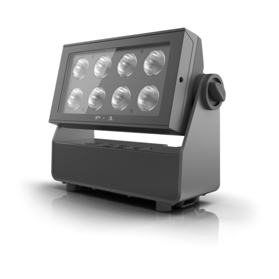
- Page 1 P-1 WASH LIGHT...
-
Page 2: Dimensions
Dimensions Measurements in millimetres. Drawing not to scale. - Page 3 © 2017 SGM Light A/S . Information subject to change without notice. SGM and all affiliated companies disclaim liability for any injury, damage, direct or indirect loss, consequential or economic loss or any other loss occasioned by the use of, inability to use or reliance on the information contained in this manual.
-
Page 4: Table Of Contents
Contents Dimensions ........................2 Safety information ......................8 Preventing electric shock............................8 Preventing burns and fire............................9 LI-ION battery ................................10 Avoid personal injury ............................... 11 Overview ........................12 Parts identification and terminology ................13 Preparing for installation ..................... 14 Unpacking................................ - Page 5 AC power, battery and charging .................. 20 AC power loss function ............................20 Battery charging and use............................20 Battery time and battery extension .......................... 20 Display panel operations ..................... 21 Using the display panel............................21 Shortcuts.................................. 21 Display ........................22 Wireless signal strength............................
- Page 6 Accessories ......................... 26 Filter frames................................26 Barndoor .................................. 27 RDM ..........................28 Sensors..................................29 Service ........................30 Cleaning................................... 30 Support hotline................................. 30 Upgrading the firmware ............................31 Control menu ....................... 32 Factory defaults ............................... 36 LED panels ................................36 DMX modes overview ....................37 DMX protocol ......................
- Page 7 Effects ......................... 52 Troubleshooting ......................53 Fixtures and accessories .................... 55 Included items................................55 Ordering information ..............................55 Approvals and certifications............................. 56 User’s notes ........................ 57...
-
Page 8: Safety Information
The P-1 is intended for professional use only. It is not suitable for household use. Impropre a l’usage domestique. Review the following safety precautions carefully before installing or operating the fixture. This product must be installed in accordance with the applicable installation code by a person familiar with the construction and operation of the product and the hazards involved. -
Page 9: Preventing Burns And Fire
Preventing burns and fire WARNING! Take measures to prevent burns and fire. • Install in a location that prevents accidental contact with the fixture. • Install only in a well-ventilated space. • Install at least 0.3 m (12 in.) away from objects to be illuminated. •... -
Page 10: Li-Ion Battery
LI-ION battery WARNING! LI-ION Battery Misusing the battery may cause the battery to get hot, rupture, or ignite and cause serious injury. Be sure to follow the safety informations listed below: • Do not place the battery in fire or heat the battery. •... -
Page 11: Avoid Personal Injury
Avoid personal injury WARNING! Take measures to prevent personal injury. • Do not look directly at the light source from close range. • Take precautions to prevent injury when working at height. • Ensure that the fixture is always securely fastened with suitable hardware. •... -
Page 12: Overview
The fixture also offers very low power consumption and an expected lifetime of the multiple LED’s of 50,000 hours*. Running for up to 12 hours in standard operation mode, the P-1 can easily be configured to provide an even output over longer periods of time. -
Page 13: Parts Identification And Terminology
Parts identification and terminology A: Dehumidifiers and GORE-TEX membranes B: DMX in and out C: Power in D: Display panel E: Holes for omega bracket F: Kensington lock socket G: Base bracket H: Safety wire attachment point... -
Page 14: Preparing For Installation
Preparing for installation Unpacking Unpack the fixture and inspect it to ensure that it has not been damaged in transport. The P-1 is shipped with: • User manual Filter frame • One Neutrik TRUE1 power input connector, 2 m (78 in.) •... -
Page 15: Location/Application
Location/application The fixture is IP65-rated and designed for use in wet locations. This means that it is protected from: • Dust; to the degree that dust cannot enter the fixture in sufficient quantities to interfere with its operation. • Lower pressure jets of water from any direction. When selecting a location for the fixture, ensure that: •... -
Page 16: Installation / Rigging
Installation / Rigging WARNING! Always secure elevated fixtures with a safety cable. The P-1 may be installed in any orientation. Always use an omega bracket to rig the fixture. Lock the bracket with the 1/4-turn fasteners. The fasteners are locked only when turned fully clockwise. -
Page 17: Rigging Process
Rigging process Start the rigging process by blocking the work area below, and make sure the work is performed from a stable platform. Check that the clamp is undamaged and can bear at least 10 times the weight of the fixture. Check that the structure can bear at least 10 times the weight of all installed fixtures, clamps, cables etc. -
Page 18: Ceiling / Wall Mount
Ceiling / wall mount The P-1 can be installed with an optional ceiling / wall mount. The ceiling / wall mount is design to fit the base bracket on the P-1. Installation • Loosen the lock screw on the ceiling / wall mount. -
Page 19: Connecting Ac Power
Connect the fixture to power using a cable with a Neutrik TRUE1 power connector (supplied with the fixture). The P-1 can also run on battery power, up to 12 hours with the possibility to extend the battery time up to 24 hours. -
Page 20: Ac Power, Battery And Charging
Battery charging and use The batteries are charging when connected to AC power and; when the P-1 is off or when the P-1 is on, but idle / not in use. The batteries do not charge while the fixture is in active use, e.g. when the light source is on. -
Page 21: Display Panel Operations
Press the ‘UP’ and ‘DOWN’ arrows simultaneously to flip the display upside-down. • To turn off the P-1, press and hold the ‘ESC’ button until the fixture turns off or go to MENU → POWER OFF. • To turn on the P-1, press any button and the fixture will power on. -
Page 22: Display
Display Wireless signal strength Displays the signal strength of the wireless CRMX connection. The wireless signal strength symbol will be flashing if the paired transmitter is out of range. If no transmitter is paired the symbol will be off. Current input type •... -
Page 23: Connecting To A Dmx Control Device
Connecting to a DMX control device The P-1 is controllable using a DMX control device and it can be connected using either a DMX cable or via the fixture’s build-in LumenRadio CRMX wireless receiver system. If using a cabled DMX system, connect the DMX in- and output cables to the connectors on the rear of the base of the fixture (chassis mounted 5-pin XLR connectors). -
Page 24: Configuring The Fixture For Dmx Control
The P-1 operates in various DMX modes. See “DMX modes overview” on page 37 for details. The first channel used to receive data from a DMX control device is known as the DMX start address. Each P-1 must have a DMX start address set. -
Page 25: Using Stand-Alone Operation
Using stand-alone operation Stand-alone operation is where the fixture is not connected to a control device, but is preprogrammed with a series of up to 24 scenes, that play continuously in a loop. Up to three stand-alone programs can be defined and run from the menus, and one of the programs can be set to run by default whenever the fixture is started. -
Page 26: Accessories
Installing the frames only requires positioning it in front of the light, and it quickly snaps in to place. The frames are fitted with a safety wire to secure the frame to the yoke on the P-1. The a filter frame can be mounted simultaneously with a barndoor. -
Page 27: Barndoor
• Release the lock pins and check that the lock pins are correctly in place. • Attach a safety wire to the barndoor and secure it to the yoke on the P-1. The barndoor can be mounted simultaneously with a filter frame. -
Page 28: Rdm
See the table below for supported RDM functions. The controller communicates with the fixtures to show only the available options for each RDM function. The P-1 supports and enable RDM, Remote Device Management, as per the ANSI E1.20 standard. Actions... -
Page 29: Sensors
Sensors RDM enables various sensor readouts for remote device monitoring. See the table below for available sensors and sensor types. Name Sensor Type Name Sensor Type Main Board Temp. Temperature AC power connected Contacts LED left Temperature Battery PCT (percentage) Other LED right Temperature... -
Page 30: Service
If in doubt, consult your SGM dealer for a suitable cleaning schedule. Clean the P-1 using a soft cloth dampened with a solution of water and a mild detergent. Do not use any product that contains solvents, abrasives or caustic agents for cleaning, as they can cause damage to both hardware, cables, connectors, plastic and painted surfaces. -
Page 31: Upgrading The Firmware
Go to the MENU → INFO → FIRMWARE VERSION. To perform firmware updates, use a Windows-based personal computer, the SGM Firmware Tool software (available on the SGM website, www.sgmlight.com) and a SGM USB 5-Pin-XLR upload cable (available from your SGM dealer). -
Page 32: Control Menu
Control menu Level 1 Level 2 Level 3 Level 4 Level 5 Info Select mode. MODE See “DMX modes overview” on page 37 QUICK COLOR GREEN BLUE RUN PROGRAM STOP PROGRAM PROGRAM Select program to edit MANUAL SCENE 1-24 Select scene to edit 0-255 Set value for red EDITOR... - Page 33 Level 1 Level 2 Level 3 Level 4 Level 5 Info FADE TIME (seconds) 0-59 Set fade time in seconds WAIT TIME (minutes) 0-120 Set wait time in minutes MANUAL EDITOR (continued) (continued) WAIT TIME (seconds) 0-59 Set wait time in seconds CLEAR PROGRAM Clear current selected program PRODUCT TYPE...
- Page 34 Level 1 Level 2 Level 3 Level 4 Level 5 Info Switches between the antenna in the head and the WIRELESS DMX EXTERNAL ANTENNA external (secondary) antenna on the rear of the (continued) head. Fixture starts up in DMX mode. SELECT STARTUP MODE STANDALONE Fixture starts up with selected standalone program.
- Page 35 Level 1 Level 2 Level 3 Level 4 Level 5 Info SERVICE PIN Enter service pin to enable service menu. MINIMUM VALUES SETTINGS The quantity of batteries installed in the fixtures (continued) SERVICE MENU NO. OF BATTERIES needs to be set in order to calculate the battery extension feature.
-
Page 36: Factory Defaults
RDM device label set to = Fixture type name • Internal program reset LED panels The P-1 offers the possibility to separate the LEDs into two panels. PANEL 1 PANEL 2 Each panel represents a cluster of four lenses. See “DMX modes overview” on page 37 for modes offering separate panels. -
Page 37: Dmx Modes Overview
DMX modes overview The P-1 operates in 8 different modes. 1 x RGB (3 channel, calibrated) 4 channel (RAW) 2 x RGB (6 channel, calibrated) Name Name Name Red PANEL 1 Green Green Green PANEL 1 Blue Blue Blue PANEL 1... - Page 38 11 channel RAW 16 channel 16 bit (calibrated) Name Name Shutter Shutter Intensity Intensity Red PANEL 1 Red PANEL 1 Green PANEL 1 Green PANEL 1 Blue PANEL 1 Blue PANEL 1 White PANEL 1 Red PANEL 2 Red PANEL 2 Green PANEL 2 Green PANEL 2 Blue PANEL 2...
-
Page 39: Dmx Protocol
DMX protocol 1 x RGB (3 channel, calibrated) Default Fader Channel Name DMX Value DMX Percentage Description Info Type Value 0,0% 100,0% No Red -> Maximum Red All panels Fade (100%) Green 0,0% 100,0% No Green -> Maximum Green All panels Fade (100%) Blue... -
Page 40: Channel Raw
4 channel RAW Default Fader Channel Name DMX Value DMX Percentage Description Info Type Value 0,0% 100,0% No Red -> Maximum Red All panels Fade (100%) Green 0,0% 100,0% No Green -> Maximum Green All panels Fade (100%) Blue 0,0% 100,0% No Blue ->... -
Page 41: Rgb (6 Channel, Calibrated)
2 x RGB (6 channel, calibrated) Default Fader Channel Name DMX Value DMX Percentage Description Info Type Value 0,0% 100,0% No Red -> Maximum Red PANEL 1 Fade PANEL 1 (100%) Green 0,0% 100,0% No Green -> Maximum Green PANEL 1 Fade PANEL 1 (100%) -
Page 42: Channel (Calibrated)
6 channel (calibrated) Default Fader Channel Name DMX Value DMX Percentage Description Info Type Value 0,0% 2,7% Closed 3,1% 5,9% Open 6,3% 59,2% Strobe Fast → Slow Shutter 59,6% 68,6% Pulse - Open Slow → Fast Snap (3,9%) 69,0% 78,0% Pulse - Close Slow →... - Page 43 Default Fader Channel Name DMX Value DMX Percentage Description Info Type Value 0,0% 100,0% No Red -> Maximum Red All panels Fade (100%) Green 0,0% 100,0% No Green -> Maximum Green All panels Fade (100%) Blue 0,0% 100,0% No Blue -> Maximum Blue All panels Fade (100%)
-
Page 44: Channel Raw
6 channel RAW Default Fader Channel Name DMX Value DMX Percentage Description Info Type Value 0,0% 2,7% Closed 3,1% 5,9% Open 6,3% 59,2% Strobe Fast → Slow Shutter 59,6% 68,6% Pulse - Open Slow → Fast Snap (3,9%) 69,0% 78,0% Pulse - Close Slow →... - Page 45 Default Fader Channel Name DMX Value DMX Percentage Description Info Type Value Blue 0,0% 100,0% No Blue -> Maximum Blue All panels Fade (100%) White 0,0% 100,0% No White -> Maximum White All panels Fade (100%)
-
Page 46: Channel (Calibrated)
9 channel (calibrated) Default Fader Channel Name DMX Value DMX Percentage Description Info Type Value 0,0% 2,7% Closed 3,1% 5,9% Open 6,3% 59,2% Strobe Fast → Slow Shutter 59,6% 68,6% Pulse - Open Slow → Fast Snap (3,9%) 69,0% 78,0% Pulse - Close Slow →... - Page 47 Default Fader Channel Name DMX Value DMX Percentage Description Info Type Value 0,0% 100,0% No Red -> Maximum Red PANEL 1 Fade PANEL 1 (100%) Green 0,0% 100,0% No Green -> Maximum Green PANEL 1 Fade PANEL 1 (100%) Blue 0,0% 100,0% No Blue ->...
-
Page 48: 11 Channel Raw
11 channel RAW Default Fader Channel Name DMX Value DMX Percentage Description Info Type Value 0,0% 2,7% Closed 3,1% 5,9% Open 6,3% 59,2% Strobe Fast → Slow Shutter 59,6% 68,6% Pulse - Open Slow → Fast Snap (3,9%) 69,0% 78,0% Pulse - Close Slow →... - Page 49 Default Fader Channel Name DMX Value DMX Percentage Description Info Type Value 0,0% 100,0% No Red -> Maximum Red PANEL 1 Fade PANEL 1 (100%) Green 0,0% 100,0% No Green -> Maximum Green PANEL 1 Fade PANEL 1 (100%) Blue 0,0% 100,0% No Blue ->...
-
Page 50: Channel, 16 Bit (Raw)
16 channel, 16 bit (RAW) Default Fader Channel Name DMX Value DMX Percentage Description Info Type Value 0,0% 2,7% Closed 3,1% 5,9% Open 6,3% 59,2% Strobe Fast → Slow Shutter 59,6% 68,6% Pulse - Open Slow → Fast Snap (3,9%) 69,0% 78,0% Pulse - Close... - Page 51 Default Fader Channel Name DMX Value DMX Percentage Description Info Type Value 0,0% 100,0% No Red -> Maximum Red PANEL 1 Fade PANEL 1 (100%) Green 0,0% 100,0% No Green -> Maximum Green PANEL 1 Fade PANEL 1 (100%) Blue 0,0% 100,0% No Blue ->...
-
Page 52: Effects
Beam angle The P-1 is equipped with a fixed 10° beam angle. The beam angle can be manipulated in various ways by utilizing one of the optional magnetic holographic filters and 4/8 way barndoors. 19°, 45°, 63°/12° elliptical plus an empty color frame) Panels The P-1 offers the possibility to control two groups of LEDs (left and right) separately. -
Page 53: Troubleshooting
The fixtures batteries are discharged. Charge the batteries by connecting AC power. Main fuse is blown. Contact SGM support or certified SGM service partner. Power was turned off. Check the power supply, switches and breakers. Fixture suddenly turned off. - Page 54 Problem Potential cause(s) Remedies Corrupted DMX cable. Replace or repair defective cables and/or connections. Fixture operates irregularly / abnormal. The fixture operates an internal program. Go to MENU → MANUAL → STOP PROGRAM (continued) A corrupted fixture generates noise/disruptions on the Track and isolate the corrupted fixture.
-
Page 55: Fixtures And Accessories
Filter frame Wide angle - 45 deg. P-1 series ........................Order no: 83061141 Filter frame Elliptical horizontal - 63 deg. (horizontal) x 12 deg. (vertical) P-1 series............Order no: 83061142 Filter frame Elliptical vertical - 12 deg. (horizontal) x 63 deg. (vertical) P-1 series..............Order no: 83061147 Barndoor 4-way, P-1 series..............................Order no: 83061138... -
Page 56: Approvals And Certifications
APPROVALS AND CERTIFICATIONS Conforms to ............................ 2014/30/EU: EMC Directive Conforms to ........................2014/35/EU: Low Voltage Directive Conforms to ..........................2011/65/EU: RoHS2 Directive RoHS The information in this document is subject to change without notice... -
Page 57: User's Notes
User’s notes... - Page 60 SGM Light A /S · Sommer vej 23 · 8210 Aarhus V · Denmark Tel +45 70 20 74 00 · info@sgmlight.com · www.sgmlight.com...
Need help?
Do you have a question about the P-1 and is the answer not in the manual?
Questions and answers