Table of Contents
Advertisement
Quick Links
Advertisement
Table of Contents

Related Manuals for SGM P-1


Summary of Contents for SGM P-1
- Page 1 USER MANUAL Product Version 1.0 | Document Revision E | Released 2023-01-10...
-
Page 2: Dimensions
All dimensions in millimeters and inches. Drawing not to scale This manual covers installation, use, and maintenance of the SGM P Series. A digital version is available at www.sgmlight.com or upon request via support@sgmlight.com. The information in this document is subject to change without notice. -
Page 3: Table Of Contents
5 SAFETY INFORMATION 6 BEFORE INSTALLING THIS PRODUCT 7 INSTALLATION STANDARD FIXTURE 7 Identification and terminology 8 Unpacking 8 Location/ application 8 Transportation 8 Rigging 9 Rigging process using SGM Omega brackets 10 Ceiling/ Wall mount 10 Tilt lock 11 Power requirements 11 Connecting power 11 Connecting data 11 Connecting a wireless transmitter 11 Disconnecting a wireless transmitter 11 Signal priority 12 USER INTERFACE 12 ... - Page 4 CONTENT 20 ACCESSORIES 20 Filter frames 20 Barndoors 21 MAINTENANCE 21 Cleaning 21 Firmware Updates 22 TROUBLESHOOTING 23 FIXTURES AND ACCESSORIES 23 Ordering information 24 SUPPORT HOTLINE 24 APPROVALS AND CERTIFICATIONS 25 USER NOTES Product Version 1.0 | Revision E | Released 2023-01-10...
-
Page 5: Safety Information
WARNING! READ THE FOLLOWING SAFETY PRECAUTIONS CAREFULLY BE- FORE UNPACKING, INSTALLING, POWERING OR OPERATING THE DEVICE. SGM fixtures are intended for professional use only. They are not suitable for household use. Les fixtures SGM sont impropre à l’usage domestique. Uniquement à usage professionnel. -
Page 6: Before Installing This Product
EXTERNAL CLEANING AND VISUAL INSPECTION OF THE FIXTURE All users of the SGM fixtures should regularly clean those parts of the fixture directly exposed to the elements, such as the external housing and front lenses. Additionally, all owners of the SGM fixtures must periodically check the external housing of the fixture for structural breaks, deteri- oration, cracked lenses, or loose screws. -
Page 7: Installation Standard Fixture
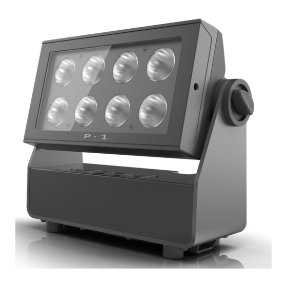
INSTALLATION STANDARD FIXTURE IDENTIFICATION AND TERMINOLOGY A: 8 x RGBW LEDs B: Tilt lock C: Power in D: DMX in and out E: Kensington lock socket F: Safety wire attachment point G: Dehumidifiers and GORE-TEX membranes H: Control panel I: OLED Display J: Holes for Omega bracket Illustrations might vary from received products. -
Page 8: Unpacking
PLEASE NOTE! THE 1/4-TURN FASTENERS ARE ONLY LOCKED WHEN TURNED FULLY CLOCKWISE. 52mm 106mm 2,047in 4,173in 14mm 18mm 0,551in 0,709in 210mm 8,268in DETAIL A SCALE 1 : 1 24mm 0,946in Figure 2: Dimensions for P-1 base locking points Product Version 1.0 | Revision E | Released 2023-01-10... -
Page 9: Rigging Process Using Sgm Omega Brackets
RIGGING PROCESS USING SGM OMEGA BRACKETS Start the standard rigging process by blocking the lower working area, and make sure the work is per- formed from a stable platform. 1. Check that the clamp/bracket is undamaged. Supporting structure should be capable of bearing at least 10 times the weight of all in- stalled fixtures, lamps, cables etc. -
Page 10: Ceiling/ Wall Mount
CEILING/ WALL MOUNT The P-1 can be installed with an optional ceiling/ wall mount. The ceiling/ wall mount is design to fit the base bracket on the P-1. To install the ceiling/ wall mount: 1. Loosen the lock screw on the ceiling/ wall mount. -
Page 11: Power Requirements
CONNECTING DATA The P-1 is controllable using a DMX control device, and it can be connected using either a DMX cable or via the fix- ture’s built-in LumenRadio CRMX wireless receiver system. When using a cabled DMX system, connect the DMX-In cable to the input connector and DMX-Out cable to the output, both on the rear of the fixture’s base (chassis mount-... -
Page 12: User Interface
USER INTERFACE The fixture can be set up by using the control panel and OLED multi-line display on fixture’s head or through RDM. The OLED display shows the current status and menu of the fixture. It is used to configure individual fixture settings and read error messages. -
Page 13: Display
DISPLAY WIRELESS SIGNAL STRENGTH Displays the signal strength of the wireless CRMX connection. The wireless signal’s strength symbol will be flashing if the paired transmitter is out of range. If no transmitter is paired the symbol will be off. CURRENT INPUT TYPE •... -
Page 14: Configuring The Device For Dmx Control
For independent control, each P-1 must be assigned its own address to have a DMX start address set. For example, if the first P-1 is set to 3ch DMX mode with a DMX address of 10, it uses the channels 10, 11 and 12. Then the following P-1 in the DMX chain should be set to a DMX address of 13. -
Page 15: Setting A Static Color Manually
This can be reset through the menu SETTINGS → STARTUP MODE → SELECT STARTUP MODE. Since firmware version 2.24, the P-1 includes a number of color presets accessible via display. To set up a color preset, select: ENTER →... -
Page 16: Fixture Properties
(see above). Beam angle The P-1 is equipped with a fixed 10° beam angle. The beam angle can be manipulated in various ways by using one of the optional magnetic holographic filters, and barndoors. -
Page 17: Control Menu
Product type Displays product type. Firmware ver- Displays installed firmware version. sion Serial number Displays SGM serial #. DRM ID Displays RDM ID. (Unique RDM ID for identification). DMX view Up to 492 DMX address- Displays received DMX levels. Sensors Mainboard Displays fixture temperatures. - Page 18 FUNCTION LEVEL 1 LEVEL 2 LEVEL 3 LEVEL 4 Info Sensors On time red 1 Display LED total power on time. (R, G, B, W). On time green 1 On time blue 1 On time white 1 On time red 2 On time green 2 On time blue 2 On time white 2...
-
Page 19: Rdm
SUPPORTED RDM FUNCTIONS The fixture features support for various RDM functions, as per the ANSI E1.20 standard. RDM (Remote Device Management) is a protocol enhancement to USITT DMX512 that allows bi-directional commu- nication between the fixtures and the controller over a standard DMX line. This protocol will allow configuration, sta- tus monitoring, and management. -
Page 20: Accessories
To install the barndoors: 1. Pull the two lock pins to the unlocked position and place the barndoor on the front of the P-1 head. 2. Release the lock pins and check the lock pins are correctly in place. -
Page 21: Maintenance
DOWNLOAD UNDER THE RESPECTIVE PRODUCT AT WWW.SGMLIGHT.COM. CLEANING SGM fixtures with IP65 or IP66-rating do not need any cleaning procedures inside the fixture. However, cleaning the front lens may be needed to achieve the maximum light output after exposure to dust, sand, or dirt. The exterior housing can also be cleaned to get a better look. -
Page 22: Troubleshooting
The minimum values are out of calibration. Contact your local SGM dealer or support@ sgmlight.com The SGM Calibration Data set has been lost. Contact your local SGM dealer or support@ sgmlight.com Product Version 1.0 | Revision E | Released 2023-01-10... -
Page 23: Fixtures And Accessories
PLEASE NOTE! THE LIST BELOW IS SUBJECT TO CHANGE WITHOUT NOTICE. The P-1 can be used with a variety of accessories. Contact your local SGM dealer to get the latest pricing and news about available accessories. ORDERING INFORMATION P-1, Std, BL (incl. 3 pcs Batt) ................P/N: 80031501 P-1, Std, WH (incl. -
Page 24: Support Hotline
SUPPORT HOTLINE SGM offers 24/7 technical support. Worldwide: +45 3840 3840 US: +1 407-242-6217 support@sgmlight.com APPROVALS AND CERTIFICATIONS Conforms to ..............2014/35/EU: Low Voltage Directive Conforms to . -
Page 25: User Notes
USER NOTES Product Version 1.0 | Revision E | Released 2023-01-10... - Page 26 SGM LIGHT A/S Sommervej 23 8210 Aarhus V Denmark Tel: +45 70 20 74 00 info@sgmlight.com www.sgmlight.com...
Need help?
Do you have a question about the P-1 and is the answer not in the manual?
Questions and answers