Table of Contents
Advertisement
Quick Links
D E G E L M A N
I N D U S T R I E S
B O X
8 3 0 - 2 7 2
I N D U S T R I A L
R E G I N A ,
S K ,
C A N A D A ,
F A X 3 0 6 . 5 4 3 . 2 1 4 0
P H 3 0 6 . 5 4 3 . 4 4 4 7
1 . 8 0 0 . 6 6 7 . 3 5 4 5
D E G E L M A N . C O M
L P
D R I V E ,
S 4 P
3 B 1
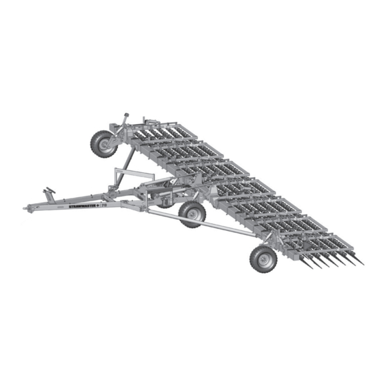
OPERATOR & PARTS
STRAWMASTER
MANUAL
143430 v1.0
+
70/90
Advertisement
Table of Contents

Related Manuals for Degelman STRAWMASTER+ 70


Summary of Contents for Degelman STRAWMASTER+ 70
- Page 1 OPERATOR & PARTS MANUAL 143430 v1.0 STRAWMASTER 70/90 D E G E L M A N I N D U S T R I E S B O X 8 3 0 - 2 7 2 I N D U S T R I A L D R I V E , R E G I N A , S K ,...
- Page 3 QUICK-START GUIDE WARRANTY STRAWMASTER REMEMBER! You must complete Product * Refer to operators manual for complete safety and operation info. Registration to be eligible for Warranty. WHEELS......Connect Hydraulics Wheel Height Cylinders TRANSPORT..... Transport Cylinders TINE ANGLE ..(Option) Harrow Section Cylinders LATCH &...
- Page 4 Setting Tine Angle, Pressure & Frame Tine Angle Adjustment There are no standard angles for running the tines, the operator Strawmaster may have either Manual or Hydraulic Tine Adjustment. may adjust the tine angles as needed to achieve desired results. Note: Manual models - Use the manual jacks Actual settings will vary...
-
Page 5: Table Of Contents
* Reference Sheet Quick-Start Guide OPERATORS SECTION - TABLE OF CONTENTS Introduction Safety Operation Pre-Operation Checklist Hook-Up Transport to Field Position Indicator Overview Settings & Adjustments Service & Maintenance Maintenance Checklist & Specifications Maintenance Free Pins & Bushings Repair - Hyd Cylinder Repair IMPORTANT: INSTALL DRY Repair - Pressed Bushing Repair - Wheel Hub... -
Page 7: Introduction
Use this manual as your first source of information about this machine. TO THE NEW OPERATOR OR OWNER - Safe, efficient and trouble free operation of your Degelman Strawmaster+ requires that you and anyone else who will be operating or maintaining it, read and understand the Safety, Operation, Maintenance and Troubleshooting information contained within this manual. -
Page 8: Safety
Safety Why is SAFETY important to YOU? 3 BIG Reasons: •Accidents Can Disable and Kill •Accidents Are Costly •Accidents Can Be Avoided SAFETY ALERT SYMBOL The Safety Alert Symbol means: he Safety Alert Symbol identifies important safety messages applied to the PRO-TILL and in this ATTENTION! manual. - Page 9 Safety SAFETY GENERAL SAFETY YOU are responsible for the safe operation and 1. Read and understand the Operator’s maintenance of your equipment. Manual and all safety signs before operating, maintaining or adjusting. YOU must ensure that you and anyone else who is going to operate, maintain or work around 2.
-
Page 10: Operation
Operation TO THE NEW OPERATOR OR OWNER BRIEF OVERVIEW OF OPERATION The Degelman Strawmaster+ is designed for • Operating speed will depend on tractor effective straw management, weed control, horsepower, environmental conditions and each herbicide application, raking flax residue while particular operation. -
Page 11: Pre-Operation Checklist
Operation BREAK-IN PRE-OPERATION CHECKLIST Although there are no operational restrictions on It is important for both personal safety and the Strawmaster+ when it is new, there are some maintaining the good mechanical condition of mechanical checks that must be done to ensure the machine that this pre-operational checklist be the long term integrity of the unit. -
Page 12: Hook-Up
Operation TRANSPORT SAFETY HOOK-UP / UNHOOKING The Strawmaster+ should always be parked on a 1. Check with local authorities regarding machine level, dry area that is free of debris and foreign transport on public roads. Obey all applicable objects. Follow this procedure to hook-up: laws and regulations. -
Page 13: Transport To Field Position
Operation TRANSPORT TO FIELD POSITION Note: Ensure there is plenty of room behind and 7) 7) to the sides of the Strawmaster before backing into field position. 7) 7) 4) 4) FULLY ROTATE end wheels BEFORE latching truss arm clamps. 1) 1) 3) 3) 1) 1) -
Page 14: Indicator Overview
Operation - Indicator Overview Tine Angle Indicator The Tine Angle Indicator is an overall visual indicator of the current setting the harrow section tine angles are set at. If you have the Hydraulic Tine Angle option, this indicator will adjust in real-time as you activate the hydraulics from the tractor. -
Page 15: Settings & Adjustments
Operation - Suggested Tine Angle Settings BREAKING & SPREADING STRAW TINE ANGLE ADJUSTMENT Strawmaster+ may have either Manual or Hydraulic • For best results operate at Tine Adjustment. Tine angle adjustment should be 10 to 12 mph. made with the machine in field position. •... - Page 16 Operation - Adjustments: Rephasing Cylinders Overview & Principles of Rephasing Troubleshooting A Rephasing Cylinder System enables a pair (or Series rephasing cylinder systems (Master and multiple) cylinders to extend and retract in very near Slave(s)) can exhibit undesirable behaviors such as unison.
-
Page 17: Service & Maintenance
Service & Maintenance MAINTENANCE SAFETY MAINTENANCE CHECKLIST • Review the Operator’s Manual and all safety items After reviewing the Maintenance and Hydraulic before working with, maintaining or operating the Safety Information, use the Maintenance Checklist Strawmaster provided for regular service intervals and keep a record of all scheduled maintenance: •... - Page 18 Service & Maintenance HARDWARE SPECIFICATIONS HYDRAULIC SAFETY Note: Unless stated otherwise, hardware is typically: • Make sure that all components in the hydraulic Hex, Plated GR5 UNC or P8.8 (metric) system are kept in good condition and are clean. • Replace any worn, cut, abraded, fl attened or TORQUE SPECIFICATIONS crimped hoses and metal lines.
- Page 19 Service & Maintenance HYDRAULIC FITTING INSTALLATION Note: A DASH size refers to a diameter of a hose (inside) or of a tube (outside) measured in 1/16” increments. The following info is to help you identify and properly For example, a Hose specifi ed as dash 8 or -8 would install some of our standard hydraulic fi...
-
Page 20: Repair - Hyd Cylinder Repair
Service & Maintenance HYDRAULIC CYLINDER REPAIR REPAIRING A THREADED HEAD CYLINDER PREPARATION Set Screw Style When cylinder repair is required, clean off unit, Barrel Set Screw disconnect hoses and plug ports before removing Gland cylinder. When removed, open the cylinder ports and drain the cylinder's hydraulic fl uid. - Page 21 Service & Maintenance REPLACING A PRESSED BUSHING NOTE: You may need the following tools: Press, hammer, punch, pry-bar, "Step-Tool" Use the following as a guideline for repair: 1. Ensure the area and frame are properly secured, supported, and safe to work on. Safely remove the pin(s), cylinder, and/or components necessary in order to access and work on the damaged bushing.
- Page 22 Service & Maintenance WHEEL HUB REPAIR WHEEL NUT & WHEEL BOLT TORQUE TORQUE BOLT PATTERNS IMPORTANT Be sure DISASSEMBLY to block up unit securely before removing tires. 1. Remove dust cap. COMMON 2. Remove cotter pin from nut. HUB & SPINDLE 5 BOLT PATTERN 6 BOLT PATTERN 8 BOLT PATTERN...
- Page 23 Service & Maintenance - Tine Replacement TINE REPLACEMENT Note: Tines must be replaced when worn down DISASSEMBLY: to 20 in. or less in length. Tines may be replaced Follow this procedure one pipe row at a time so while the machine is in transport position, or field pipes do not get mixed up, or number each pipe position.
-
Page 24: Troubleshooting
Troubleshooting GENERAL TROUBLESHOOTING In the following section, we have listed some of the problems, causes, and solutions that you may encounter. If you encounter a problem that is difficult to solve, even after having read through this troubleshooting section, please call your local dealer or distributor. Before you call, have this manual and the serial number from your unit ready. - Page 25 -19- 143430 - SM HARROW (12-February-2021)
-
Page 26: Front Trailer Overview
Front Trailer Overview Front Trailer Assembly Overview (90' Model Configuration Shown) Spring Bar Assembly 90' Overview (7 Row shown) Exploded Front Trailer Component Overview Center Beam Cross Transport Joint Cylinders Model Trailer Height Center Beam Indicator Torsion Indicator Swing Arm 70' Model Latch Arm Assembly... -
Page 27: Wing Assembly Overview
Wing Overview LH Wing Assembly Overview 90' Overview (7 Row shown) Exploded LH Wing Component Overview (70' - 7 Row Model Shown) Harrow Sections (7 Row shown) Light Mounts Sign Truss Mount Holder Mount Jack Mount Spring Bar Hose Clamp Assemblies Mount Brackets Jack... -
Page 28: Front Trailer Components
143162 - Decal, Read 132030 - Jack, 142761 - Decal, 142008 - Decal, Manual (1) Sidewind (1) Lock Circuit (1) Degelman - 6 (1) 142963 - Decal, Neg 142750 - Tongue Weight (1) Decal, Hoses 142753 - 142964 - Decal,... -
Page 29: Latch & Swing Arm Components
Latch & Swing Arm Components Latch Assembly Components 90' Latch Assembly 70' Latch Assembly Overview Overview NOTE: The components for both 70' & 90' Latch Assemblies are identical, with the exceptions of the 'Latch Arms' and 'Latch Hooks'. Exploded Latch Components (LH 90' exploded assembly shown) 117414 - Lock Nut, 3/4 GRC Unitorque (8) 118775 - Flat Washer, 3/4 F436 (16) - Page 30 Rock Shaft & Wheel Components Rock Shaft Components Cast Bearing Assembly IMPORTANT: Torque to 117225 - Bushing, 2-1/2 OD x 2 (4) Components (2) 550 lb . ft (750 N . m) 133135 - Wiper Seal, 2-1/2 OD (4) 118178 - Bolt, 1 123066 - Cylinder, Monarch x 11 - GR8 (2) - 4-1/4 x 8 x 2 (2)
-
Page 31: Center & Wing Beam Components
Center Beam & Transport Cylinder Components Center Beam Components 249465 - Tine Deflector, RH (1) 249466 - Tine Deflector, LH (1) Hose Clamp Locations 118767 - Bolt, 7/8 x 3 (2) Differ Between Models 7 Row Model Shown 118774 - Flat washer, 7/8 - F436 (4) 575212 - Pin Head (2) (4 Row and 5 Row 117416 - Lock Nut, 7/8 Unitorq (2) - Page 32 70' Wing Beam & Truss Overview 70' Beam Exploded Overview (Individual component breakdowns may be located on other pages) Tine Angle Indicator (1) (Refer to Harrow Sections for Tine Stop Info) 249470 - Wing Beam Assembly, 70 (2) 142557 - Amber 132041 - Jack, Reflector, 2 x 9 (2) Sidewind (2)
- Page 33 90' Wing Beam & Truss Overview 90' Beam Exploded Overview (Individual component breakdowns may be located on other pages) Pipe Tine Guard Mount (2) Tine Angle Indicator (1) (Refer to Harrow Sections for Tine Stop Info) 249300 - Wing Beam Assembly, 142557 - 90 (2) Amber Reflector,...
- Page 34 Wing Beam Bracket Components Spring Bar Mount Truss Holder Mount 118048 - Bolt, 3/4 x 2-1/2 (8) 243061 - Bar, 117414 - Lock Nut, Back-up (1) 118775 - Flat Washer, 3/4 Unitorque (1) 3/4 - F436 (16) 118775 - Flat Washer, 117414 - Lock Nut, 118056 - 3/4 F436 (2)
-
Page 35: End Wheel Components
End Wheel Assembly Components End Wheel Overview (LH Shown - RH is Mirrored) End Wheel Components 249310 - Transport Wheel Holder (2) 249348 - Collar (2) 118911 - Lock Nut, 1 (2) top mounts with... 118113 - Bolt, 1 x 9 (2) 118048 - Bolt, 3/4 x 2-1/2 GR8 (4) 118336 - Grease 118775 - Flat Washer, 3/4 F436 (8) -
Page 36: Harrow Section Layout & Components
Harrow Section Layout & Manual Tine Adjustment HARROW SECTION LAYOUT OVERVIEW TINE ANGLE ADJUSTMENT Hydraulic Adjustment Manual Adjustment (Available) 132065 - Jack, Ratchet (7 or 9) 132066 - Jack Handle, 8” (1) 118849 - Cotter Pin, 10' 10' 10' 10' 10' 10' 10' 1/4 x 2-1/2 (1) (3-Wing) (Center) - Page 37 Harrow Section Components - 7 Row 10’ WING HARROW SECTION OVERVIEW - 7 ROW 10’ CENTER HARROW SECTION OVERVIEW - 7 ROW 244771 - Wing 244830 - Center Harrow Section Harrow Section Frame, 10’ - 7 Row Frame, 10’ - 7 Row 10’...
- Page 38 Harrow Section Components - 5 Row 10’ WING HARROW SECTION OVERVIEW - 5 ROW 10’ CENTER HARROW SECTION OVERVIEW - 5 ROW 243035 - Wing 244841 - Center Harrow Section Harrow Section Frame, 10’ - 5 Row Frame, 10’ - 5 Row 10’...
- Page 39 Harrow Section Components - 4 Row 10’ WING HARROW SECTION OVERVIEW - 4 ROW 10’ CENTER HARROW SECTION OVERVIEW - 4 ROW 247502 - Wing 244896 - Center Harrow Section Harrow Section Frame, 10’ - 4 Row Frame, 10’ - 4 Row 10’...
- Page 40 Hydraulic Option - Tine Angle (70' Models) Hydraulic Fittings Required 141581 - Coupler Tip, 141581 - Coupler Tip, 3/4 ORB F 3/4 ORB-F (2) 141676 - Connector, 3/4 ORB M x M 141676 - Connector, 141686 - Coupler, Brown (+) 3/4 ORB M x M (2) 141687 - Coupler, Brown (-) 141686 - Coupler,...
- Page 41 Hydraulic Option - Tine Angle (90' Models) Hydraulic Fittings Required 141581 - Coupler Tip, 141581 - Coupler Tip, 3/4 ORB F 3/4 ORB-F (2) 141676 - Connector, 3/4 ORB M x M 141676 - Connector, 141686 - Coupler, Brown (+) 3/4 ORB M x M (2) 141687 - Coupler, Brown (-) 141686 - Coupler,...
-
Page 42: Hydraulic Routing - Latch & End Wheel
Hydraulic Layout - Latch & Endwheel Steering 141581 - Coupler Tip, 3/4 ORB-F (2) Hydraulic Fittings Required 141581 - Coupler Tip, 3/4 ORB F 141676 - Connector, 141676 - Connector, 3/4 ORB M x M 3/4 ORB M x M (2) 141688 - Coupler, Black (+) 141689 - Coupler, –... -
Page 43: Hydraulic Routing - Wheel Height
Hydraulic Layout - Wheels 141581 - Coupler Tip, 3/4 ORB-F (2) Hydraulic Fittings Required 141581 - Coupler Tip, 3/4 ORB F 141676 - Connector, 141676 - Connector, 3/4 ORB M x M 3/4 ORB M x M (2) 141684 - Coupler, Green (+) 141685 - Coupler, –... -
Page 44: Hydraulic Routing - Transport
Hydraulic Layout - Transport Hydraulic Fittings Required 141581 - Coupler Tip, 141581 - Coupler Tip, 3/4 ORB F 3/4 ORB-F (2) 141676 - Connector, 3/4 ORB M x M 141676 - Connector, 141682 - Coupler, Blue (+) 3/4 ORB M x M (2) 141683 - Coupler, Blue (+) 141682- Coupler, 141703 - Adaptor, 1/2 ORB M x ORFS M... -
Page 45: Electrical Layout & Light Components
Electrical Layout / Light Components Wire Harness - w/plugs (1) 249481 - SM+ 70' 249480 - SM+ 90' Follow Hose Routing & attach with Zip Ties LH Wing Only 70' Qty (1) 90' Qty (2) 118735 - Screw, 1/4-20 x 3/4 129042 - Clamp, Rubber Cushion 129127 - Lamp,... -
Page 46: Warranty
Re-torque of fastening hardware, Hydraulic fluid purities, drive train alignments, and clutch operation) 3. If parts not made or supplied by Degelman have been used in the connection with the unit, if, in the sole judgement of Degelman such use affects its performance, safety, stability or reliability. -
Page 47: B O X
It is the retail customer’s responsibility to deliver the product to the authorized Degelman dealer, from whom he purchased it, for service or replacement of defective parts, which are covered by warranty. Repairs to be submitted for warranty consideration must be made within forty-five days of failure.
Need help?
Do you have a question about the STRAWMASTER+ 70 and is the answer not in the manual?
Questions and answers