Table of Contents
Advertisement
Advertisement
Table of Contents

Related Manuals for horiba OCMA-500


Summary of Contents for horiba OCMA-500
- Page 1 Oil Content Analyzer OCMA-500 Instruction Manual CODE:GZ0000331784D...
- Page 2 HORIBA Advanced Techno Co., Ltd. warrants that the Product shall be free from defects in material and workmanship and agrees to repair or replace free of charge, at option of HORIBA Advanced Techno Co., Ltd., any malfunctioned or damaged Product attributable to responsibility of HORIBA Advanced Techno Co., Ltd.
- Page 3 Regulations Conformable Directive This equipment conforms to the following directives and standards: EMC: EN61326-1 Class B, Basic electromagnetic environment Safety: EN61010-1 RoHS: EN50581 9. Industrial monitoring and control instruments Warning: This product is not intended for use in industrial environments. In an industrial environment, electromagnetic environmental effects may cause the incorrect performance of the product in which case the user may be required to take adequate measures.
- Page 4 FCC rules Any changes or modifications not expressly approved by the party responsible for compliance shall void the user's authority to operate the equipment. Warning This equipment has been tested and found to comply with the limits for a Class A digital device, pursuant to part 15 of the FCC Rules.
- Page 5 For Your Safety Hazard classification and warning symbols Warning messages are described in the following manner. Read the messages and follow the instructions carefully. Hazard classification This indicates an imminently hazardous situation which, if not avoided, will result in death or serious injury. This is to be limited to the most extreme situations.
-
Page 6: Safety Precautions
Safety precautions This section provides precautions for using the product safely and correctly and to prevent injury and damage. The terms of DANGER, WARNING, and CAUTION indicate the degree of imminency and hazardous situation. Read the precautions carefully as it contains important safety messages. - Page 7 CAUTION Take care not to pinch your fingers when opening or closing the right cover. During closing the right cover, do not release your hand until you hear a click sound. Avoid any impact on the product. If the product is damaged and liquid leaks, the internal wiring may short-circuit. If liquid containing hydrochloric acid leaks and comes in contact with the skin, irritation and burning may occur.
- Page 8 Product Handling Information Operational precautions Use of the product in a manner not specified by the manufacturer may impair the protection provided by the product. And it may also reduce product performance. Observe the cautions below. This product is specified for use with H-997. Do not use any other solvent than H-997 to ...
- Page 9 Solvent handling precautions It is recommended that new solvent from the same production lot is used for calibration liquid preparation, zero calibration, span calibration, and measurement. Solvents from different production lots may have different mix ratios. If it is necessary to use solvents from different production lot or reprocessed solvent, mix all the volumes to be used in a glass container, in order to equalize all mix ratios.
- Page 10 Manual Information Description in this manual Note This interprets the necessary points for correct operation and notifies the important points for handling the product. Reference This indicates the part where to refer for information. This indicates reference information. Original language This is the original in English.
-
Page 11: Table Of Contents
Contents Product Outline ........Overview. - Page 12 Using B-heavy oil ..........Hydrochloric acid .
- Page 13 Examples of measurement by extraction outside the product ..Oil content in water ..........Oil content in or on solids.
- Page 14 System Setting screen ........Language .
- Page 15 Troubleshooting ........106 Alarm displays and actions .
- Page 16 Figures Fig. 1 Exterior....................Fig. 2 Extraction tank window ................ Fig. 3 Right inside ..................Fig. 4 Operation buttons................. Fig. 5 Measurement/calibration screen example ........... Fig. 6 Example of item selection screen ............Fig. 7 Pop-up screen example (selection list) ..........Fig.
- Page 17 Fig. 53 Separating the solvent layer..............Fig. 54 Visually checking the solvent layer ............Fig. 55 Removing water from the solvent layer..........Fig. 56 Oil content extraction from part (immersion) ........Fig. 57 Data Top screen................... Fig. 58 Current Alarm screen ................Fig.
- Page 18 Fig. 106 Correct packing position ............... Fig. 107 Incorrect packing position ..............Fig. 108 Extraction tank on the packing.............. Fig. 109 Extraction tank on the packing.............. Fig. 110 Packing runs off the inside of the extraction tank ......... Fig. 111 Removing the sample inlet ..............Fig.
- Page 19 Tables Table 1 Operable buttons with the instantaneous value measurement screen Table 2 Operable buttons with a selection list pop-up screen ......Table 3 Operable buttons with a numeric key pop-up screen ......Table 4 Operable buttons with a character key pop-up screen ...... Table 5 Example of span liquid preparation ...........
-
Page 21: Product Outline
Simple button operations execute extraction, measurement, and drainage automatically. OCMA-500 allows a measurement using 8 mL of solvent and 16 mL of measurement liquid. It also allows a measurement using 10 mL of solvent and 20 mL of measurement liquid like... -
Page 22: Accessories
The package contains the main unit and accessories indicated below. Make sure that none of the items are missing or damaged. Name Remarks Quantity Image Main unit OCMA-500 Dropper Polyethylene, 2.5 mL B-heavy oil 10 mL Filter element For water filter... -
Page 23: Part Names
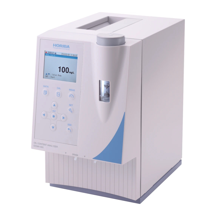
Product Outline Part names Exterior Fig. 1 Exterior Name Description This displays measurement results and items necessary for various operations. Operation buttons Buttons for performing a variety of operations Extraction tank window Allows you to check conditions inside the extraction tank. Drainage outlet from Liquid is drained from the measurement cell through this outlet. -
Page 24: Extraction Tank Window
Use a FAT/FAT32 formatted USB memory stick. Other formats may not be available with this product. Even FAT/FAT32 formatted, some USB memory sticks may not work. In this case, try other type. If you need the USB memory stick manufactured and verified by HORIBA Advanced Techno, contact your local dealer. -
Page 25: Operation Buttons
Product Outline Note Always keep the right cover closed during measurement. Stable measurement cannot be performed when the right cover is open. Operation buttons Fig. 4 Operation buttons Name Image Description Press this button to open the Data Top screen DATA button (refer to "Data Top screen"... -
Page 26: Lcd
Product Outline Name Image Description Press this to enter the current selection or value, or move to the next action. ENT button In the manual mode, press this button to start measurement (refer to "Screen operations in the manual measurement/calibration mode" (page 14)). Press to undo the last action and return to the previous process. -
Page 27: Fig. 6 Example Of Item Selection Screen
Product Outline Example of item selection screen This screen appears for the operations of data management or setting. Reference "Data Top screen" (page 57) "Setting Top screen" (page 69) Fig. 6 Example of item selection screen Example of pop-up screen ... -
Page 28: Fig. 8 Pop-Up Screen Example (Numeric Keys)
Product Outline Numeric keys These appear when the settings function is used to select a setting item that requires entry of a numerical value. Reference "Numeric keys" (page 17) "Setting" (page 69) Fig. 8 Pop-up screen example (numeric keys) Character keys If [Save Memo] is set to "ON"... -
Page 29: Main Unit Setup
Main Unit Setup Main Unit Setup Putting the valve stickers If you use the manual measurement/calibration mode, it may be useful to put the valve stickers on the operation button panel as shown below. Fig. 10 Positions of the valve stickers Placing the absorbent sheet Follow the steps below to place the absorbent sheet on the tray in the main unit. -
Page 30: Basic Operation
Basic Operation Basic Operation Power ON WARNING Electric shock To prevent electric shock, ground the product. Do not ground the product to dangerous places such as a gas pipe. 1. Insert the provided power cable into the power cable connector on the back of the main unit. -
Page 31: Power Off
Basic Operation Fig. 14 Measurement Top screen Note The main unit is not stable while the warm-up icon blinks. Although measurement is possible while the warm-up icon blinks, the alarm icon will blink after measurement is finished and an invalid data error will occur (refer to "Current Alarm screen" (page 58) and "Alarm displays and actions"... -
Page 32: Drainage Mode Operation
Basic Operation Drainage mode operation You can start liquid drainage manually by changing to the drainage mode. The procedure for draining liquid in the drainage mode is explained below. 1. Press the up or down button with the Measurement Top screen appearing until the process display shows [Drainage]. -
Page 33: Connecting A Usb Memory Stick
Even FAT/FAT32 formatted, some USB memory sticks may not work. In this case, try other type. If you need the USB memory stick manufactured and verified by HORIBA Advanced Techno, contact your local dealer. Do not lose the cap for the USB memory port. -
Page 34: Screen Operations In The Manual Measurement/Calibration Mode
Basic Operation Fig. 17 USB icon Screen operations in the manual measurement/calibration mode On the instantaneous value measurement screen, which appears when the manual measurement mode, manual zero calibration mode, or manual span calibration mode starts, you can switch to any operations below to control extraction, cell filling, measurement, and drain manually. - Page 35 Basic Operation The relations between part control and product operation are shown in the table below. Product operation Stirring motor Fill cell valve Drainage valve Extraction Closed Closed Cell filling Open Closed Measurement Open Closed Drainage (all) Open Open Drainage (solvent) Closed Open...
-
Page 36: Using Pop-Up Screens
Basic Operation Using pop-up screens A pop-up screen for selection or entry will appear when it is necessary for you to select an item or enter a number or characters when configuring settings or performing other operations. If [Save Memo] is set to "ON" in the measurement settings, a pop-up screen will appear for entering the data name, before measured values being saved. -
Page 37: Numeric Keys
Basic Operation Numeric keys This screen is used to configure settings. Numeric keys and an input box appear. Reference " Setting " (page 69) Fig. 20 Example of numeric key pop-up screen The buttons and button functions, which can be used with a numeric key pop-up screen appearing, are described in the table below. -
Page 38: Character Keys
Basic Operation Character keys This screen is used to enter names of memo data such as measurement conditions. If [Save Memo] is set to "ON" in the measurement settings, this screen appears immediately before measured values are saved. Reference "Save Memo"... -
Page 39: Preparation
Preparation Preparation Measurement preparation cautions CAUTION Chemical hazard (solvent S-316) Inhalation or accidental ingestion of a large amount of solvent S-316 may be harmful. Observe the following rules when handling: • Ventilate the work area sufficiently. • Wear a protective mask and protective gloves. •... -
Page 40: Glassware
Preparation Glassware Items required Beakers (200 mL): 1 or 2 (for drainage) Measuring cylinders (20 mL) or syringes (20 mL, optional): 2 (for solvent and sample) Solvent S-316 (optional) Zero liquid for calibration (refer to "Zero liquid for calibration" (page 21)) ... -
Page 41: Zero Liquid For Calibration
Using B-heavy oil Use B-heavy oil (specific gravity 0.895 at 20°C) to prepare span liquid for OCMA-500. When you know the oil type to be measured, you can also use that oil type for the calibration oil. Items required ... -
Page 42: Hydrochloric Acid
Preparation Hydrochloric acid When an acid is added to a water sample containing organic matter, the solvent and the sample separate easily (salting-out effect). When performing oil content extraction, the salting-out effect can be produced by adding approx. 6 mol/L hydrochloric acid. The procedure for preparing 6 mol/L hydrochloric acid using commercially available concentrated hydrochloric acid (36%) is explained below. -
Page 43: Condition Settings
Preparation Condition settings Standard calibration conditions and measurement conditions are set by default in the product. Once the warm-up icon has turned off, calibration and measurement can be started immediately. Calibration condition settings The default settings for the calibration conditions and the pages to refer to for the setting procedures are shown below. -
Page 44: Calibration
Calibration Calibration Calibration cautions CAUTION Chemical hazard (solvent S-316) Inhalation or accidental ingestion of a large amount of solvent S-316 may be harmful. Observe the following rules when handling: • Ventilate the work area sufficiently. • Wear a protective mask and protective gloves. •... - Page 45 Calibration Purging is necessary to prevent effects from the previous measurement liquid. Set [Number of Purge] from 2 to 6. If the concentration changes by 100 mg/L or more from the previous measurement, set [Number of Purge] to 5 or more. When using the built-in extractor, maintain an extraction ratio of solvent:water = 1:2.
-
Page 46: Points To Check Prior To Calibration
Are the beakers for drainage in place? beakers for drainage" (page 20)). Items required Zero calibration OCMA-500 (this product) Measuring cylinders (20 mL) or syringes (20 mL, optional): 2 (for solvent and sample) Dropper (provided): 1 (for hydrochloric acid) ... -
Page 47: Automatic Zero Calibration
Calibration Automatic zero calibration 1. Set the calibration mode to "AUTO" on the Calibration Setting screen. Change other settings as needed. Reference "Calibration condition settings" (page 23) "Calibration Setting screen" (page 80) 2. Press the CAL button or up/down button with the Measurement Top screen appearing until the process display shows [Auto Zero Calibration]. -
Page 48: Automatic Span Calibration
Calibration Fig. 24 Display of automatic zero calibration result When drainage is completed, the start state of the automatic zero calibration mode returns. 7. Repeat steps 3. to 6. until the set [Number of Purge] is completed and measurement starts. Automatic span calibration 1. -
Page 49: Fig. 26 Display Of Automatic Span Calibration Result
Calibration 6. Press the ENT button. If the set [Number of Purge] has not been completed: The purge sequence starts. The screen title changes to [Auto Span Calibration (Purge: 1)], and the process display changes as follows as the sequence progresses: [Extraction] →... -
Page 50: Manual Zero Calibration
Calibration Manual zero calibration 1. Set the calibration mode to "MANUAL" on the Calibration Setting screen. Change other settings as needed. Reference "Calibration condition settings" (page 23) "Calibration Setting screen" (page 80) 2. Press the CAL button or up/down button with the Measurement Top screen appearing until the process display shows [Manual Zero Calibration]. -
Page 51: Fig. 29 Manual Zero Calibration - Measurement
Calibration 9. Press the ENT button. Measurement starts. The operation guide display shows [ESC: Cancel]. The elapsed time is shown (counting up). When measurement ends, the calibration result appears. Fig. 29 Manual zero calibration - Measurement When measurement ends normally, the measured value is held. The operation guide display shows [ESC: Return]. -
Page 52: Manual Span Calibration
Calibration Manual span calibration 1. Set the calibration mode to "MANUAL" on the Calibration Setting screen. Change other settings as needed. Note The value set in [Span Point] in the calibration settings must be adjusted based on the extraction ratio. For example, when the extraction ratio is solvent:water = 1:2, set 1/2 the value of the actual concentration of the span liquid for calibration in [Span Point] in the calibration settings. -
Page 53: Fig. 33 Manual Span Calibration - Measurement
Calibration 7. If needed, execute purging (extraction, cell filling, and drainage) referring to "Screen operations in the manual measurement/calibration mode" (page 14). 8. Execute extraction and fill the cell at any time referring to steps 3. to 6. and "Screen operations in the manual measurement/calibration mode"... -
Page 54: Measurement
Measurement Measurement Measurement cautions CAUTION Chemical hazard (solvent S-316) Inhalation or accidental ingestion of a large amount of solvent S-316 may be harmful. Observe the following rules when handling: • Ventilate the work area sufficiently. • Wear a protective mask and protective gloves. •... - Page 55 Measurement Purging is necessary to prevent effects from the previous measurement liquid. Set [Number of Purge] from 2 to 6. If the concentration changes by 100 mg/L or more from the previous measurement, set [Number of Purge] to 5 or more. When using the built-in extractor, maintain an extraction ratio of solvent:water = 1:2.
-
Page 56: Preprocessing
Measurement Preprocessing Removing fine particles If the sample water contains fine particles or other impurities, use an ashless cellulose quantitative filter paper (particle retention: 8 m) to remove the impurities before dispensing the sample into the product. Fig. 35 Removal of fine particles ... -
Page 57: Items Required
Measurement Items required OCMA-500 (this product) Measuring cylinders (20 mL) or syringes (20 mL, optional): 2 (for solvent and sample) Dropper (provided): 1 (for hydrochloric acid) Clean solvent S-316 (optional) Hydrochloric acid (refer to "Hydrochloric acid" (page 22)) ... -
Page 58: Flow Scheme Of Operation
Measurement Flow scheme of operation Fig. 36 Operation flow of automatic measurement... -
Page 59: Procedure
Measurement Procedure 1. Set the measurement mode to "AUTO" on the Measurement Setting screen. Change other settings as needed. Reference "Measurement condition settings" (page 23) "Measurement Setting screen" (page 70) 2. Press the MEAS button or up/down button until the process display on the screen shows [Auto Measurement]. -
Page 60: Fig. 38 Auto Measurement - Measurement
Measurement Fig. 38 Auto Measurement - Measurement Note During layer separation, make sure that the solvent and sample water separate sufficiently. If the solvent and sample water are insufficiently separated, press the ESC button to cancel measurement, and lengthen [Separation Time] in the measurement settings. If the nature of the sample is such that layer separation is difficult, it is recommended that you use semi-automatic measurement or manual measurement in advance to determine the optimum [Separation Time]. -
Page 61: Semi-Automatic Measurement
Measurement Semi-automatic measurement Flow scheme of operation Fig. 39 Operation flow of semi-automatic measurement... -
Page 62: Procedure
Measurement Procedure 1. Set the measurement mode to "SEMI-AUTO" on the Measurement Setting screen. Change other settings as needed. Reference "Measurement condition settings" (page 23) "Measurement Setting screen" (page 70) 2. Press the MEAS button or up/down button until the process display on the screen shows [Semi-Auto Measurement]. -
Page 63: Fig. 42 Semi-Automatic Measurement - Layer Separation
Measurement 7. Press the ENT button. Layer separation starts. The process display on the screen shows [Layer Separation]. The elapsed time appears (counting up). Fig. 42 Semi-automatic measurement - Layer separation 8. Make sure that the solvent and sample water have sufficiently separated, and press the ENT button. - Page 64 Measurement If [Confirm Save] is set to "MANUAL", the operation guide display will show [ENT: Save ESC: Skip]. To save the measured value, press the ENT button. To skip, press the ESC button. For details on the [Confirm Save] setting, refer to "Confirm Save" (page 78). If [Save Memo] is set to "ON"...
-
Page 65: Manual Measurement
Measurement Manual measurement Flow scheme of operation Fig. 45 Operation flow of manual measurement... -
Page 66: Procedure
Measurement Procedure 1. Set the measurement mode to "MANUAL" on the Measurement Setting screen. Change other settings as needed. Reference "Measurement condition settings" (page 23) "Measurement Setting screen" (page 70) 2. Press the MEAS button or up/down button until the process display on the screen shows [Manual Measurement]. -
Page 67: Fig. 48 Manual Measurement - Measurement
Measurement 9. Press the ENT button. Measurement starts. The elapsed time is shown (counting up). When measurement ends, the measured value appears. Fig. 48 Manual measurement - Measurement If [Confirm Save] is set to "MANUAL", the operation guide display will show [ENT: Save ESC: ... -
Page 68: Examples Of Measurement By Extraction Outside The Product
Measurement Examples of measurement by extraction outside the product This section describes examples of extraction performed outside the product without using the built-in extractor. The methods described below are only examples for reference. These methods may not be the optimum methods for some sample types. Use an extraction and measurement method that is appropriate for the actual sample. -
Page 69: Fig. 50 Mixing Solvent And Sample Water By Shaking
Measurement Checking procedure 1. Dispense 8 mL of solvent and 16 mL of sample water into the glass container with a lid. 2. Screw the lid closed and shake for 1 minute by hand. Fig. 50 Mixing solvent and sample water by shaking 3. - Page 70 Measurement Extraction Items required Separating funnel (300 mL) : 2 (for sample extraction and for zero point checking) Measuring cylinder (200 mL) : 3 (for sample, for solvent, and for clean water) Dropper (provided): 1 (for hydrochloric acid) ...
-
Page 71: Fig. 52 Extraction
Measurement 6. Use the pH meter to check the pH value (pH 2 to pH 3) of each separating funnel (for sample extraction and for zero point checking). 7. Insert the stopper in each separating funnel (for sample extraction and for zero point checking) and shake for approx. -
Page 72: Fig. 53 Separating The Solvent Layer
Measurement Removing water from the solvent layer 1. Collect only parts that can be recognized as solvent in the glass container, and check the status of the liquid. If no water particles are visible and the liquid is clear, use it as measurement liquid. If you can see water particles with a diameter of 0.1 mm or larger or the liquid appears whitish overall, follow the steps below to remove water from the solvent layer. - Page 73 Measurement 4. Continue performing step 3. until the solvent layer is clear. 5. If anhydrous sodium sulfate crystals remain, filter with filter paper. 6. After waiting, collect the supernatant liquid using a measuring utensil and use this as measurement liquid. Zero calibration ...
-
Page 74: Oil Content In Or On Solids
Measurement Oil content in or on solids Directly immerse the part in the solvent to extract the oil content. Although an ultrasonic cleaner can be used for extraction. The solvent volatilization volume and changes in water content will be larger and may have a greater effect on the measured value. -
Page 75: Fig. 56 Oil Content Extraction From Part (Immersion)
Measurement Fig. 56 Oil content extraction from part (immersion) Note Do not shake the container with the solvent and with closed lid hard. If it is shaken hard, the internal pressure will increase due to vaporization of the solvent and the solvent may spray out from gaps under the lid. - Page 76 Measurement Span calibration Perform span calibration using the conditions in the table below. Parameter Condition Span Point Concentration of span liquid Extraction Time 0 sec Separation Time 0 sec Number of Purge 3 or more Span liquid for calibration Use 24 mL of span liquid for calibration.
-
Page 77: Data Management
Data Management Data Management Data Top screen The Data Top screen appears when the DATA button is pressed on the Measurement Top screen or Setting Top screen. The Data Top screen shows a menu for data management. Select an item with the up/down button and press the ENT button to move to the screen for the selected function. -
Page 78: Current Alarm Screen
Data Management Button Function Page Down button Selects the next item down. ESC button Returns to the Measurement Top screen. page 10 Current Alarm screen If [Current Alarm] is selected on the Data Top screen, the Current Alarm screen opens. The Current Alarm screen shows a list of the current alarms. -
Page 79: Measurement History Screen
Data Management Measurement History screen If [Measurement History] is selected on the Data Top screen, the Measurement History screen opens. The Measurement History screen shows a list of the measurement history. Fig. 59 Measurement History screen The buttons and button functions, which can be used with the Measurement History screen appearing, are described in the table below. -
Page 80: Calibration History Screen
Data Management Calibration History screen If [Calibration History] is selected on the Data Top screen, the Calibration History screen opens. The Calibration History screen shows a list of the calibration history. Fig. 60 Calibration History screen The buttons and button functions, which can be used with the Calibration History screen appearing, are described in the table below. -
Page 81: Usb Memory Screen
Even FAT/FAT32 formatted, some USB memory sticks may not work. In this case, try other type. If you need the USB memory stick manufactured and verified by HORIBA Advanced Techno, contact your local dealer. To execute the operations with the USB Memory screen appearing, a USB memory stick must be ... -
Page 82: Execution Confirmation For [Save Measurement History]
Data Management Button Function Page ESC button Returns to the Data Top screen page 57 Execution confirmation for [Save Measurement History] This is a confirmation message for saving the measurement history to a USB memory stick. Fig. 62 Execution confirmation for [Save Measurement History] The buttons and button functions, which can be used with the execution confirmation for [Save Measurement History] appearing, are described in the table below. -
Page 83: Execution Confirmation For [Save Calibration History]
Data Management Execution confirmation for [Save Calibration History] This is a confirmation message for saving the calibration history to a USB memory stick. Fig. 63 Execution confirmation for [Save Calibration History] The buttons and button functions, which can be used with the execution confirmation for [Save Calibration History] appearing, are described in the table below. -
Page 84: Execution Confirmation For [Save Settings]
Data Management Execution confirmation for [Save Settings] This is a confirmation message for saving the settings of the main unit to a USB memory stick. Fig. 64 Execution confirmation for [Save Settings] The buttons and button functions, which can be used with the execution confirmation for [Save Settings] appearing, are described in the table below. -
Page 85: Fig. 65 Setting File Example
Data Management Setting item category Item (data ID) Description Page SpanValue Set span value page 81 ExtractTime Extraction time page 81 CalibrationSetting LayerSeparationTime Separation time page 82 PurgeNum Numbers of purges page 82 CalMode Calibration mode page 83 SystemSetting Language Language setting page 85 An example of a setting file is shown in Fig. -
Page 86: Memory Clear Screen
Data Management Memory Clear screen If [Memory Clear] is selected on the Data Top screen, the Memory Clear screen opens. The Memory Clear screen shows a menu for selection of data to be deleted from internal memory. If an item is selected with the up/down button and the ENT button is pressed, an execution confirmation message for deletion of the selected data appears. -
Page 87: Execution Confirmation For [Clear Measurement History]
Data Management Execution confirmation for [Clear Measurement History] This is a confirmation message for clearing the measurement history. Fig. 67 Execution confirmation for [Clear Measurement History] The buttons and button functions, which can be used with the execution confirmation for [Clear Measurement History] appearing, are described in the table below. -
Page 88: Execution Confirmation For [Clear Calibration History]
Data Management Execution confirmation for [Clear Calibration History] This is a confirmation message for clearing the calibration history. Fig. 68 Execution confirmation for [Clear Calibration History] The buttons and button functions, which can be used with the execution confirmation for [Clear Calibration History] appearing, are described in the table below. -
Page 89: Setting
Setting Setting Setting Top screen The Setting Top screen appears when the SET button is pressed on the Measurement Top screen or the Data Top screen. The Setting Top screen shows a menu for setting. Select an item with the up/down button and press the ENT button to move to the screen for the selected function. -
Page 90: Measurement Setting Screen
Setting Button Function Page Down button Selects the next item down. ESC button Returns to the Measurement Top screen. page 11 Measurement Setting screen If [Measurement Setting] is selected on the Setting Top screen, the Measurement Setting screen opens. The Measurement Setting screen shows the current measurement settings. If an item is selected with the up/down button and the ENT button is pressed, a pop-up screen appears to let you change the setting of the selected item. -
Page 91: Table 24 Button Functions With The Measurement Setting Screen
Setting Setting range (unit) Item Description Page or selections 1.0 to 10000.0 Sets the sample volume used as a coefficient when the (The units depend on Sample Vol. page 76 measured value is converted to mg/kg, mg/g, or mg/PC. the set [Measurement Unit].) Zero Shift Value Sets the shift correction value for zero liquid. -
Page 92: Extraction Time
Setting Extraction Time Use this screen to set the extraction time in the automatic measurement mode. Fig. 72 Extraction Time screen The following settings are available. The default setting is 40 (sec). Setting range Units 0 or 10 to 600 For the buttons and functions, which can be used with this screen appearing, refer to Table 3 (page 17). -
Page 93: Fill Cell Time
Setting Fill Cell Time Use this screen to set the cell filling time in the automatic measurement and automatic calibration modes. Fig. 74 Fill Cell Time screen The following settings are available. The default setting is 60 (sec). Setting range Units 30 to 3600 For the buttons and functions, which can be used with this screen appearing, refer to Table 3... -
Page 94: Drainage Time
Setting Drainage Time Use this screen to set the drainage time in the automatic measurement and automatic calibration modes. Fig. 76 Drainage Time screen The following settings are available. The default setting is 30 (sec). Setting range Units 30 to 3600 For the buttons and functions, which can be used with this screen appearing, refer to Table 3 (page 17). -
Page 95: Meas. Mode
Setting Meas. Mode Use this screen to set the measurement mode. Fig. 78 Meas. Mode screen The following settings are available. The default setting is "AUTO". Selection Description AUTO If the MEAS button is pressed, the automatic measurement mode is entered. SEMI-AUTO If the MEAS button is pressed, the semi-automatic measurement mode is entered. -
Page 96: Solvent Vol
Setting Solvent Vol. Use this screen to enter the solvent volume to be used as a coefficient for conversion of the measurement unit into mg/kg, mg/g, or mg/PC. Reference "Conversion of measurement units" (page 112) Fig. 80 Solvent Vol. screen The following settings are available. -
Page 97: Zero Shift Value
Setting Zero Shift Value Use this screen to set the shift correction value for zero liquid. The sum of this set value and the raw measured value is displayed as the measured value. Reference "Conversion of measurement units" (page 112) Fig. -
Page 98: Confirm Save
Setting Confirm Save Use this screen to set whether saving of settled measured values to internal memory takes place automatically or by manual selection. Fig. 84 Confirm Save screen The following settings are available. The default setting is "AUTO". Selection Description AUTO... -
Page 99: Display Negative
Setting Display Negative Use this screen to set whether a negative value is displayed or zero is displayed when the measured value is a negative value. Fig. 86 Display Negative screen The following settings are available. The default setting is "OFF". Selection Description If the measured value is a negative value, zero is displayed. -
Page 100: Calibration Setting Screen
Setting Calibration Setting screen If [Calibration Setting] is selected on the Setting Top screen, the Calibration Setting screen opens. The Calibration Setting screen shows the current calibration settings. If an item is selected with the up/down button and the ENT button is pressed, a pop-up screen appears to let you change the setting of the selected item. -
Page 101: Span Point
Setting Span Point Use this screen to set the concentration of the span liquid for calibration. Fig. 89 Span Point screen The following settings are available. The default setting is 200 (mg/L). Setting range Units 1.0 to 200.0 mg/L For the buttons and functions, which can be used with this screen appearing, refer to Table 3 (page 17). -
Page 102: Separation Time
Setting Separation Time Use this screen to set the layer separation time in the automatic calibration mode. Fig. 91 Separation Time screen The following settings are available. The default setting is 30 (sec). Setting range Units 0 or 10 to 600 For the buttons and functions, which can be used with this screen appearing, refer to Table 3 (page 17). -
Page 103: Calib. Mode
Setting Calib. Mode Use this screen to set the calibration mode. Fig. 93 Calib. Mode screen The following settings are available. The default setting is "AUTO". Selection Description AUTO If the CAL button is pressed, the automatic calibration mode is entered. MANUAL If the CAL button is pressed, the manual calibration mode is entered. -
Page 104: System Setting Screen
Setting System Setting screen If [System Setting] is selected on the Setting Top screen, the System Setting screen opens. The System Setting screen shows the current system settings. If an item is selected with the up/down button and the ENT button is pressed, a pop-up screen appears to let you change the setting of the selected item. -
Page 105: Language
Setting Language Use this screen to set the system language. Fig. 95 Language screen The following settings are available. The default setting is "ENGLISH". Selection Description ENGLISH Displays in English. JAPANESE Displays in Japanese. RUSSIAN Displays in Russian. For the buttons and functions, which can be used with this screen appearing, refer to Table 2 (page 16). -
Page 106: Date
Setting Date Use this screen to set the date. Fig. 97 Date screen The following settings are available. Setting range 2000/01/01 to 2099/12/31 For the buttons and functions, which can be used with this screen appearing, refer to Table 3 (page 17). -
Page 107: Maintenance
Maintenance Maintenance Contact for maintenance Manufacturer: HORIBA Advanced Techno Co., Ltd. 31, Miyanonishi-cho, Kisshoin Minami-ku, Kyoto 601-8306, Japan Maintenance item list To keep this product in good condition and operating at top performance, perform maintenance regularly. Table 29 Maintenance items... -
Page 108: Rinsing The Flow Paths
Maintenance Rinsing the flow paths CAUTION Chemical hazard (solvent S-316) Inhalation or accidental ingestion of a large amount of solvent S-316 may be harmful. Observe the following rules when handling: • Ventilate the work area sufficiently. • Wear a protective mask and protective gloves. •... -
Page 109: Inspecting The Absorbent Sheet
Maintenance Inspecting the absorbent sheet CAUTION Chemical hazard (solvent S-316) Inhalation or accidental ingestion of a large amount of solvent S-316 may be harmful. Observe the following rules when handling: • Ventilate the work area sufficiently. • Wear a protective mask and protective gloves. •... -
Page 110: Cleaning The Fan Filter
Maintenance Cleaning the fan filter If the filter, attached to the fan vent, starts to clog and the internal temperature rises, accurate measurement values can no longer be obtained and there is a risk of product failure. Clean the fan filter on a regular basis. ... -
Page 111: Washing The Fan Filter
Maintenance Washing the fan filter If the filter, attached to the fan vent, starts to clog and the internal temperature rises, accurate measurement values can no longer be obtained and there is a risk of product failure. Wash the fan filter on a regular basis. ... -
Page 112: Washing The Extraction Tank
Maintenance Washing the extraction tank CAUTION Chemical hazard (solvent S-316) Inhalation or accidental ingestion of a large amount of solvent S-316 may be harmful. Observe the following rules when handling: • Ventilate the work area sufficiently. • Wear a protective mask and protective gloves. •... -
Page 113: Fig. 103 Removing The Sample Inlet
Maintenance 3. Pull out the latch knobs (2 places). Fig. 103 Removing the sample inlet Fig. 104 Latch knobs 4. Disconnect the extractor joint and motor connector, and remove the extractor. 5. Loosen the fixing screw and remove the extraction tank. Fig. -
Page 114: Fig. 106 Correct Packing Position
Maintenance 8. Assemble the extractor. Reverse the stirrer unit, and put the packing on the plane surface inside the threaded portion so as not to protrude from the stirrer unit. Fig. 106 Correct packing position Fig. 107 Incorrect packing position 9. -
Page 115: Fig. 109 Extraction Tank On The Packing
Maintenance 10. Tighten a fixing screw slowly. If you feel resistance of the packing, tighten the fixing screw 45 degree or until the end. Excessive tightening may twist the packing, resulting leakage. Fig. 109 Extraction tank on the packing 11. Make sure that there is no backlash between the stirrer unit and the extraction tank. Observe the inside of the extraction tank and make sure that the packing does not run off the inside. - Page 116 Maintenance 19. Press the ENT button. The instantaneous value measurement screen appears. 20. Close the drainage valve and open the fill cell valve referring to "Screen operations in the manual measurement/calibration mode" (page 14). Cell filling starts. 21. Make sure that there is no liquid leakage from the extraction tank. If liquid is leaking, reassemble the extractor.
-
Page 117: Removing Liquid From The Air Hole Of The Extractor
Maintenance Removing liquid from the air hole of the extractor CAUTION Chemical hazard (solvent S-316) Inhalation or accidental ingestion of a large amount of solvent S-316 may be harmful. Observe the following rules when handling: • Ventilate the work area sufficiently. •... -
Page 118: Fig. 113 Removing Liquid From The Air Hole
Maintenance 6. Use the syringe to inject air into the air hole at the top of the extractor and remove the liquid from the air hole. Fig. 113 Removing liquid from the air hole 7. Reverse the above procedure to replace the extractor in its original position. 8. -
Page 119: Replacing The Water Filter
Maintenance Replacing the water filter CAUTION Chemical hazard (solvent S-316) Inhalation or accidental ingestion of a large amount of solvent S-316 may be harmful. Observe the following rules when handling: • Ventilate the work area sufficiently. • Wear a protective mask and protective gloves. •... -
Page 120: Fig. 114 Opening The Right Cover
Maintenance 1. Turn OFF the power. 2. Open the right cover. Fig. 114 Opening the right cover 3. Remove the joints from the filter block. Fig. 115 Removing the joints... -
Page 121: Fig. 116 Replacing The Water Filter Element
Maintenance 4. Loosen the fastening screws and remove the filter block. Fig. 116 Replacing the water filter element 5. Remove the packing and filter element, and wipe off any liquid in the filter block and on the packing with tissue paper. 6. -
Page 122: Drying The Measurement Cell
Maintenance 17. After liquid drainage is finished, press the ESC button. The start state of the manual measurement mode returns. 18. Close the right cover. Drying the measurement cell CAUTION Chemical hazard (solvent S-316) Inhalation or accidental ingestion of a large amount of solvent S-316 may be harmful. Observe the following rules when handling: •... -
Page 123: Fig. 117 Opening The Right Cover
Maintenance 1. Turn OFF the power. 2. Open the right cover. Fig. 117 Opening the right cover 3. Remove the joints from the filter block. Fig. 118 Removing the joints... -
Page 124: Fig. 119 Replacing The Water Filter Element
Maintenance 4. Loosen the fastening screws and remove the filter block. Fig. 119 Replacing the water filter element 5. Remove the packing and filter element, and wipe off any liquid in the filter block and on the packing with tissue paper. 6. - Page 125 Maintenance 11. Set the measurement mode to "MANUAL" on the Measurement Setting screen. Reference "Measurement condition settings" (page 23) "Measurement Setting screen" (page 70) 12. Press the MEAS button or up/down button until the process display on the screen shows [Manual Measurement].
-
Page 126: Troubleshooting
Troubleshooting Troubleshooting Alarm displays and actions If an alarm occurs, the alarm icon at the top of the LCD flashes. You can check the current alarm on the Current Alarm screen. Reference For information on the Current Alarm screen, refer to "Current Alarm screen" (page 58). ... - Page 127 Troubleshooting Display Description Cause Action Hardware error in stirrer The motor has Motor (S) Contact your local dealer or service station. motor. failed. Flow path switching at the top of the main unit The motor has Flow (U) Contact your local dealer or service station. does not finish within the failed.
-
Page 128: Problems Not Indicated By An Alarm
Troubleshooting Problems not indicated by an alarm Corrective actions for problems that are not indicated by an alarm are described below. If a problem other than one of the problems below occurs, or if a problem is not resolved after the corrective action is taken, contact your local dealer or service station. - Page 129 Troubleshooting Problem Cause Action Replace the water filter (refer to "Replacing the The water filter is noticeably dirty. water filter" (page 99)). The sample water was measured Calibrate using the same extraction conditions as after calibration with solvent only. for measurement. Use a thermometer to monitor the room temperature and keep the room temperature constant during measurement.
- Page 130 Troubleshooting Note Even when the same solvent is used for calibration and measurement, minute water content effects may cause the indicated value to be negative. If needed, remove water from the solvent layer referring to "Examples of measurement by extraction outside the product" (page 48), and then perform measurement.
-
Page 131: Reference
Reference Reference About this product Measurement principle As indicated in Fig. 121, oils have an absorption band in the vicinity of wavelengths 3.4 m to 3.5 m (2941 cm to 2857 cm ) based the expansion and contraction of groups such as (-CH -) and (-CH ) that are particular to hydrocarbons. -
Page 132: Measurement Time
Reference Measurement time This product automatically determines the stability of the measured value. For this reason, at least 20 seconds is required from the start of measurement until display of the measurement results. The flow of measurement is as follows: 1. -
Page 133: Solvent S-316
Reference Solvent S-316 Characteristics Solvent S-316 has the characteristics shown below, and satisfies the conditions required of a solvent for oil content extraction. Although there is absorption near the 3000 cm absorption wavelength of the hydrocarbon group, this absorption can be clearly distinguished from that of oil. Available for measurement in wide range of temperature due to the boiling point of 134°C ... -
Page 134: Storing Solvent
Reference Separation of solvent Processing time can be reduced by separating solvent with a high oil concentration from solvent a low oil concentration before reclamation. Keep solvent, which has been used for calibration and measurement in containers separate from unused solvent, and further separate by use and/or oil concentration. For example, it is recommended that zero calibration liquid, span calibration liquid, low concentration sample liquid, and high concentration sample liquid are reclaimed separately. -
Page 135: Frequently Asked Questions
Reference Frequently asked questions Solvents Question Answer In addition to a different extraction solvent, the principle of measurement used for the What are the main extracted oil content is different. differences between The OCMA detects oil content by infrared absorption, whereas the normal hexane analysis using S-316 and method measures the weight of the oil content. - Page 136 Reference Question Answer Soil in a powder form with no water content: Remove any rocks, grass, etc. Weigh out 1 g to 100 g of the soil (the optimum amount depends on the oil content concentration). Add solvent to the sample and stir. Filter with filter paper or quartz wool.
-
Page 137: Solvent Reclamation Unit
Reference Solvent reclamation unit SR-305 Question Answer When solvent is passed When using new activated carbon, reclaim 300 mL of used solvent in advance. through new activated This solvent will almost completely disappear due to adsorption by the activated carbon carbon, heat generation surface and heat generation. - Page 138 Reference Question Answer In general, replace both the activated carbon and activated alumina when the aggregate load oil quantity exceeds 1400 mg. However, the critical load oil quantity depends on the oil type. What are the guidelines for The aggregate load oil quantity can be calculated from the oil content concentration and replacement of activated amount of reclaimed solvent using the equation below.
-
Page 139: Product Information
Product Information Product Information Specifications Model OCMA-500 Product name Oil content analyzer Measurement method Solvent extraction - non-dispersive infrared absorption analysis method Substances extracted from sample water into solvent and having infrared Measured objects absorption near a wavelength from 3.4 m to 3.5 m... - Page 141 Headquarters 31, Miyanonishi-cho, Kisshoin Minami-ku, Kyoto 601-8306, Japan TEL:+81-75-321-7184 FAX:+81-75-321-7291...
Need help?
Do you have a question about the OCMA-500 and is the answer not in the manual?
Questions and answers