
Subscribe to Our Youtube Channel
Related Manuals for horiba APDA-372


Summary of Contents for horiba APDA-372
- Page 1 Ambient Air Analyzers APDA-372 / APDA-372 E FINE-DUST MONITORING SYSTEM Instruction Manual Version: HE0050419, valid as of firmware version 100449...
- Page 2 INSTRUCTION MANUAL APDA-372 / APDA-372 E FINE DUST MONITORING SYSTEM ©HORIBA Europe GmbH Version HE0050419 Jul-19...
- Page 3 These instructions describe the operation for the Fine-Dust Monitoring Systems, APDA-372 and APDA-372 E. Be certain to read this manual before using the product in order to ensure that the device is operated properly and safely. You should also save the manual in a reliable manner so that it is readily available whenever required.
- Page 4 INSTRUCTION MANUAL APDA-372 / APDA-372 E FINE DUST MONITORING SYSTEM CE conformity declaration The APDA-372 / APDA-372 E complies with the regulations of the European directives: Directive: EMC directive 89/336/EC Low voltage directive 73/23/EC Standards: EMC directive EN61326-1: 2006 Electrical equipment for...
-
Page 5: Table Of Contents
Integrating the measuring system in the measuring station ................. 18 2.1. General ..................................18 2.2. Positioning and connection of the APDA-372 control unit ................ 18 2.3. Installing the Sigma-2 sampling head ......................20 2.4. Switching on the measuring system ........................ 20 Notes on the system .............................. - Page 6 INSTRUCTION MANUAL APDA-372 / APDA-372 E FINE DUST MONITORING SYSTEM 5.14. Servicing of the pump assembly ........................53 Particle detection with the APDA-372 system ....................54 6.1. Special properties of the APDA-372 system ....................57 6.2. Overview of the individual measuring steps ....................58 6.3.
- Page 7 Figure 3: Front of the APDA-372 control unit ......................13 Figure 4: Back of the APDA-372 control unit ......................13 Figure 5: Connections on the back of the APDA-372 control unit ................. 14 Figure 6: Connection of the external aerosol sensor unit ..................15 Figure 7: Initial screen ............................
- Page 8 Figure 47: Measurement of the scattered light signal on the individual particle..........55 Figure 48: Comparison of an optical scattered light spectrometer with ............... 56 Figure 49: Measurement in the vicinity of streets with the APDA-372 ..............56 Figure 50: Penetration curves used ........................60 Figure 51: Penetration curves used ........................
-
Page 9: Important - Please Take Note
• and detection limit, can be found in the VDI Guideline 3489, Sheet 3. The APDA-372 is shipped in the state in which it was subjected to the TÜV equivalence test. This • also applies for the device version APDA-372 E. If corrections are to be made to this state, please take section 3.5 into account. - Page 10 INSTRUCTION MANUAL APDA-372 / APDA-372 E FINE DUST MONITORING SYSTEM ©HORIBA Europe GmbH Version HE0050419 Jul-19...
-
Page 11: Installation And Initial Commissioning
1.2. Verify the completeness of the delivery When the APDA-372 is transported by a carrier, the APDA-372 system is dismantled into its components. The system must be reassembled once again before initial commissioning. The following parts must be present: Figure 1: Components of an APDA-372 system ©HORIBA Europe GmbH... -
Page 12: Figure 2: External Aerosol Sensor Unit Apda-372 E
INSTRUCTION MANUAL APDA-372 / APDA-372 E FINE DUST MONITORING SYSTEM The following components and documentation should be present for all versions (The letters in parentheses refer to the items in Figure 1). APDA-372 control unit (a) Printed instruction manual for APDA-372... -
Page 13: Device Overview
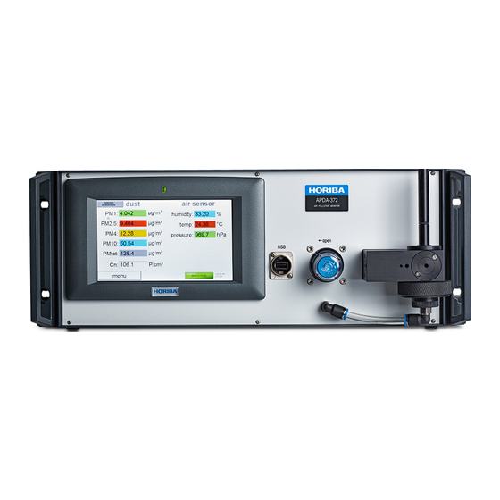
Front view of the APDA-372 control unit Figure 3: Front of the APDA-372 control unit The APDA-372 device is operated via a touchscreen (for more on this, see the separate APDA-372 firmware instruction manual which includes detailed information on the user interface). -
Page 14: Connections On The Back Of The Control Unit
The LED switches on with the mains switch. The operating hours counter runs as long as the device is on. The light source has a service life (MTTF) of >20,000 operating hours. The LED in the APDA-372 is operated at 20% of capacity with a controlled, lower temperature, which considerably prolongs the service life. -
Page 15: Apda-372 E - External Aerosol Sensor Unit
1.3.4. APDA-372 E – External aerosol sensor unit With the APDA-372 E, the entire aerosol sensor unit is separate from the control unit and is installed in a separate housing, which easily enables flexible installation in a measuring station. The... -
Page 16: First Measurement
APDA-372 / APDA-372 E FINE DUST MONITORING SYSTEM 1.4. First measurement Switch the device on (I/0 switch on the back of the APDA-372 control unit). The measurement process begins automatically when the device is switched on. The measured data are also automatically stored in the internal memory. The initial screen appears after the device has started (see figure 6). -
Page 17: Figure 8: Data Overview, E.g. Pm Values
Cn: Particle concentration in P/cm3 Figure 8: Data overview, e.g. PM values More detailed information can be found in the separate instruction manual for the APDA-372 firmware. Please note: The value “NaN” (no number) appears briefly after the device is switched on and before the first measurement or during calibration or maintenance. -
Page 18: Integrating The Measuring System In The Measuring Station
2. Integrating the measuring system in the measuring station 2.1. General The measuring systems APDA-372 and APDA-372 E are designed for setup in a temperature controlled environment (climate-controlled measuring station or the like). The measuring system can be installed in an equipment rack or on a table top. -
Page 19: Figure 10: Connecting The Sampling Tube With The Sampling Inlet Tube And The Control Unit
INSTRUCTION MANUAL APDA-372 / APDA-372 E FINE DUST MONITORING SYSTEM Figure 10: Connecting the sampling tube with the sampling inlet tube and the control unit Continue with this step until the sampling tube directly touches the sensor unit, meaning there should no longer be any gap. -
Page 20: Installing The Sigma-2 Sampling Head
Figure 13: Installing the Sigma-2 sampling head 2.4. Switching on the measuring system Switch on the mains switch on the back of the APDA-372 control unit. After launching the Windows operating system and the APDA-372 Start-up Manager, you will see the screen with the various different PM fractions, the particle number concentration and the ambient conditions (temperature, relative humidity, air pressure). -
Page 21: Notes On The System
APDA-372 / APDA-372 E FINE DUST MONITORING SYSTEM 3. Notes on the system 3.1. As-delivered condition of the measuring system The as-delivered condition of the APDA-372 is the same as the condition of the measuring system during the qualification test with the following default settings: Parameter... - Page 22 Selected communication protocol upon start-up (see below legend) temperature_compensation=yes LED temperature control [DO NOT CHANGE!] temperature_slope=0.17 Setting 0.17 for APDA-372 and 0.19 for APDA-372 E [DO NOT CHANGE!] velocity_correction=yes Dynamic border zone correction [DO NOT CHANGE!] velocity_calibration_enabled=no [DO NOT CHANGE!] flow_calibration_enabled=yes Calibration of flow rate is possible (button under "sensor calibration")
-
Page 23: Activating The Coincidence Correction
This is the same setting that is used in the type approval testing. If the APDA-372 is used at installation sites at which significantly high concentrations can occur, and if the APDA-372 measures a coincidence value of greater than 10%, it may be necessary to activate the coincidence correction in order to significantly broaden the original concentration range of 0 to 10,000 µg/m... -
Page 24: Figure 16: Expert User Menu
APDA-372 / APDA-372 E FINE DUST MONITORING SYSTEM You are now in the Expert User menu (Figure 16). You can return to the APDA-372 main menu from here by clicking on the green APDA-372 bar at the top left. Please click on “system” to continue: Figure 16: Expert user menu You are now in the “System”... -
Page 25: Figure 18: Advanced System Settings
INSTRUCTION MANUAL APDA-372 / APDA-372 E FINE DUST MONITORING SYSTEM Caution: Please do not change anything other than what is described below. Otherwise you run the risk that your device will no longer function properly! Figure 18: Advanced system settings You are now in the hidden calibration screen. -
Page 26: Changing The Moving-Average Time Basis For Apda-372 Measurements
• by “-” and click on “accept” (see Figure 15). You are now in the Expert User menu (Figure 16). You can return to the APDA-372 main menu from • here by clicking on the green APDA-372 bar at the top left. Please click on “system” to continue: You are now in the “system”... -
Page 27: Figure 21: Startup Folder
Various different files can be seen in this folder (scroll downwards to see the second half; see Figure 22). File Purpose “_palassupport.exe” Teamviewer module for remote support and remote control “counter-win32.100###.exe” APDA-372 user interface firmware; the highest number is the most current version “DATA_auto_5048_...” APDA-372 files “promo.ini” APDA-372 *.ini file with permanent settings ©HORIBA Europe GmbH... -
Page 28: Figure 22: Fidas Folder
INSTRUCTION MANUAL APDA-372 / APDA-372 E FINE DUST MONITORING SYSTEM Figure 22: Fidas folder Please open the “promo.ini” file. For the APDA-372, it should appear as follows (see Figure 23): [system] type=Fidas 200 ser#=XXXX password=yxcvbXXXX user_device#= [plugin] Promo 3000_enabled=no Fidas 100_enabled=yes... -
Page 29: Figure 23: The Promo.ini File
INSTRUCTION MANUAL APDA-372 / APDA-372 E FINE DUST MONITORING SYSTEM [Fidas] velocity_calibrated=9.3 m/s PM10_slope=1.000 PM10_intercept=0 PM4_slope=1.000 PM4_intercept=0 PM2.5_slope=1.000 PM2.5_intercept=0 PM1_slope=1.000 PM1_intercept=0 PMtotal_slope=1.000 PMtotal_intercept=0 PM_alternative=yes PM_volatile=no textfile=yes textfile_interval=60s PM_autoadjust=no gravimetric_correction_factor=1.00 IADS_modus=1 dust_type=2 sensor_selection=2 automated_cleaning=no alarm_threshold=99999 µg/m³ alarm_value=PM10 alarm_email_address="" password_service=-1 calibration_IADS_restrict=yes calibration_temperature=50... - Page 30 INSTRUCTION MANUAL APDA-372 / APDA-372 E FINE DUST MONITORING SYSTEM The second half can be viewed by scrolling downwards. Please check the time basis and, if necessary, set the time basis for the moving average value to 900 seconds (i.e. 15 minutes). Save and close the “promo.ini”...
-
Page 31: Corrections Used For The Algorithm, E.g. Tüv Correction For Pm2.5 And Pm10
0.945 cAxis intercept: -1.422 If this correction for measurements with the APDA-372 is to be used, it must be entered in the promo.ini file. The same procedure applies for other corrections, such as of a location correlation that has been determined with respect to a gravimetric measurement system. -
Page 32: System Monitoring Functions
APDA-372 / APDA-372 E FINE DUST MONITORING SYSTEM 3.6. System monitoring functions The APDA-372 measuring system is delivered with the system monitoring activated. If the firmware is not running or has crashed, the system is restarted automatically after 255 seconds. However, this also means that access to the Windows operating system is limited to 255 seconds if the access is initiated via the following path: “expert user menu”... -
Page 33: System Modifications And Installation Of Additional Software Under Windows
Windows system clock and the date. The only exception is for data that are saved on the desktop. The APDA-372 data and system files are also saved on the desktop and can be modified at any time, and new files can be added. -
Page 34: Maintenance
APDA-372 / APDA-372 E FINE DUST MONITORING SYSTEM 4. Maintenance We recommend a periodic inspection of the correct operation of the APDA-372 according to the following table and section 5. Apart from this, the device only needs to be serviced if one of the error Figure 25). -
Page 35: Figure 25: Status Overview
Figure 25: Status overview Various items of sensor information are shown here which are required for correct operation of the APDA-372. This information is also saved along with every data record in the form of a status/error byte. This specifically includes: Sensor flow The APDA-372 regulates the volumetric flow rate at 4.8 l/min by means of a control circuit with... - Page 36 20%. Suction pumps The volumetric flow in the APDA-372 is generated by two pumps that are connected in parallel. If one pump fails, the other can assume its role; the power consumption is then accordingly higher, which leads to an error.
-
Page 37: Calibration/Verification Of The Apda-372
+10 °C to +40 °C! The device must be switched to the calibration mode for the calibration. To do so, select “settings/calibration” in the main menu of the APDA-372 firmware. In the next screen select “activate calib mode”. Return to the main menu. - Page 38 Disassemble the sampling head. Loosen the mount of the IADS tube and raise it about 20 cm to gain access to the aerosol inlet of the APDA-372 sensor. Secure the IADS in this position. Close off the aerosol inlet with a cap / plug / clamped off piece of hose or your thumb.
-
Page 39: Flow Rate Test / Calibration
The result should be < 0.5 l/min. If this value is exceeded, check the IADS for damaged ring seals and correct seating of the aerosol inlet of the APDA-372 sensor. Also check whether the IADS inlet is really closed off tightly. Repeat the leak test until the result is acceptable –... -
Page 40: Check Of The Particle Sensor Offset
[settings] area: flow_calibration_enabled=yes 5.3. Check of the particle sensor offset The check of the particle sensor offset is only a monitoring measurement – contact your APDA-372 supplier if the measured values lie outside of the specified range. 5.3.1 In the main menu, select the “expert user menu”... -
Page 41: Check Of The Particle Sensor Zero Point
INSTRUCTION MANUAL APDA-372 / APDA-372 E FINE DUST MONITORING SYSTEM Figure 26: Screen display during the automatic offset adjustment 5.4. Check of the particle sensor zero point Checking and possibly calibrating the particle sensor zero point must only be carried out after a successful leak test (5.1) and sensor offset (5.3). -
Page 42: Check Of The Average Particle Velocity
INSTRUCTION MANUAL APDA-372 / APDA-372 E FINE DUST MONITORING SYSTEM If the value is not zero, check to see if the filter is perhaps not seated tightly or there is electronic interference (interference sources). If the problem continues, please contact your APDA-372 supplier. -
Page 43: Figure 27: Screen Display During The Calibration
The APDA-372 will draw in particle-laden air and the “raw data distribution” graph will display a signal peak. The firmware will recognize the location of the peak and display the numerical value as “measured peak at …”. - Page 44 In the event of substantial deviation (> 10 channels) between the measured position of the MonoDust 1500 signal peak and the target value, contact your APDA-372 supplier. An evaluation of the effect of a shift of the peak in the raw data channel with respect to the mass concentration was carried out in the context of the type approval testing by TÜV...
-
Page 45: Check Of The Velocity With Monodust Particles
INSTRUCTION MANUAL APDA-372 / APDA-372 E FINE DUST MONITORING SYSTEM Figure 28: Excerpt from TÜV Rheinland Report 936/21226418/C 5.7. Check of the velocity with MonoDust particles In addition to the signal amplitude for each individual particle, the sensor also measures the signal length for each individual particle. -
Page 46: Saving The Data
(except for “velocity at cursor”). Compare the velocity value with the value that is listed in the APDA-372 calibration certificate (measurement performed at either 35 or 50 °C, depending on what is indicated on the certificate). - Page 47 INSTRUCTION MANUAL APDA-372 / APDA-372 E FINE DUST MONITORING SYSTEM Test Test interval Tested parameter Limit values Comment Leak test 3 months Flow rate by sealing off the intake < 0.08 l/min (control unit) < 0.5 l/min (overall system) (excluding the pump...
-
Page 48: Removal Of The Gravimetric Filter / Filter Replacement
INSTRUCTION MANUAL APDA-372 / APDA-372 E FINE DUST MONITORING SYSTEM 5.9. Removal of the gravimetric filter / filter replacement To remove the gravimetric filter, the gravimetric filter holder on the bottom of the aerosol sensor must be removed. Figure 29: (A-C) Removing the filter holder The filter holder (Figure 29A) can easily be pulled off downwards (Figure 29B). -
Page 49: Cleaning The Apda-372
When using an IADS humidity compensation module, it must first be removed from the aerosol inlet of the sensor so that the APDA-372 control unit with the integrated aerosol sensor can be moved aside. Figure 31: Connection of the sensor inlet with IADS humidity compensation module The adapter for connecting the IADS humidity compensation module on the aerosol inlet must be pushed downwards. -
Page 50: Figure 33: Unscrewing The M3 Phillips Head Screws
INSTRUCTION MANUAL APDA-372 / APDA-372 E FINE DUST MONITORING SYSTEM Figure 34: Removing the aerosol guide tube Figure 33: Unscrewing the M3 Phillips head screws Caution: When removing the aerosol guide tube, care must be taken to ensure that the... -
Page 51: Cleaning The Exhaust Filter Of The Internal Pump
INSTRUCTION MANUAL APDA-372 / APDA-372 E FINE DUST MONITORING SYSTEM 5.11. Cleaning the exhaust filter of the internal pump The filter must be cleaned or replaced if the power required by the exhaust pump is greater than 50%. The protective cover of the exhaust filter (Figure 37) of the internal pump can be released and pulled off easily by rotating it to the left. -
Page 52: Replacing The O-Ring Seal
If a leak test or a visual inspection reveals that an O-ring seal must be replaced, we recommend only using the O-ring seals that HORIBA supplies. HORIBA offers a “set of O-ring seals for the APDA-372” as a spare part item. This set consists of the following O-ring seals:... -
Page 53: Servicing Of The Pump Assembly
APDA-372 / APDA-372 E FINE DUST MONITORING SYSTEM 5.14. Servicing of the pump assembly The volumetric flow in the APDA-372 is generated by two pumps (= pump assembly) that are connected in parallel. The pumps used require no maintenance during operation. The pump performance is monitored continuously (also see section 4). -
Page 54: Particle Detection With The Apda-372 System
APDA-372 / APDA-372 E FINE DUST MONITORING SYSTEM 6. Particle detection with the APDA-372 system The APDA-372 is an optical aerosol spectrometer which uses the principle of light scattering according to Lorenz Mie to determine the size of individual particles. -
Page 55: Figure 46: Calibration Curve For 90° Scattered Light Detection
INSTRUCTION MANUAL APDA-372 / APDA-372 E FINE DUST MONITORING SYSTEM Figure 46: Calibration curve for 90° scattered light detection With a monochromatic light source (left) and with a polychromatic light source (right) For each individual particle, a scattered light pulse is generated that is recorded at an angle of from 85°... -
Page 56: Figure 48: Comparison Of An Optical Scattered Light Spectrometer With
(Figure 49). Figure 49: Measurement in the vicinity of streets with the APDA-372 (Size range from 0.18 µm, blue curve) compared with a different optical measurement system (size range from 0.25 µm, red curve) -
Page 57: Special Properties Of The Apda-372 System
INSTRUCTION MANUAL APDA-372 / APDA-372 E FINE DUST MONITORING SYSTEM 6.1. Special properties of the APDA-372 system The APDA-372 system is characterized by the following properties: Using the techniques presented unambiguous calibration curve (polychromatic light and 90° scattered light detection) •... -
Page 58: Overview Of The Individual Measuring Steps
INSTRUCTION MANUAL APDA-372 / APDA-372 E FINE DUST MONITORING SYSTEM 6.2. Overview of the individual measuring steps Particles of different sizes Representative „suction“ of particles in ambient air with Sigma-2 Drying of particles with IADS (Intelligent Aerosol Drying System) Measurement of scattered light intensity with white light and 90° scattered light at the single particle... - Page 59 Calculation of the particle mass by using a size depended transformation function depending on the form of the distribution PM value The APDA-372 uses the measured particle size information to calculate the following dust values: PM-1[µg/m ]: Dust fractions smaller than d = 1 µm in accordance with the US EPA...
-
Page 60: Figure 50: Penetration Curves Used
INSTRUCTION MANUAL APDA-372 / APDA-372 E FINE DUST MONITORING SYSTEM The dust fractions mentioned above are calculated using the penetration curves for standardized sampling heads to EN-481 (PM-respirable, PM-thoracic and PM-alveolar) as well as of the US EPA (PM- 1, PM-2.5, PM10). - Page 61 0.7 and 3 g/cm³, and the shape factor χ particle between 1 and 1.5. For the calculation of the PM values, the APDA-372 assumes a density of 1.5 g/cm and a shape factor of 1. These values are suitable for most aerosols. However, the APDA-372 is equipped with a gravimetric filter system which can be used for the measurement of the correction factor C.
-
Page 62: Additional Advantages
(whereby a time resolution of one second is technically feasible with the APDA-372 system), since the physical properties of the particles are decisive for a prediction of the dispersion. -
Page 63: Definition Of Terms
INSTRUCTION MANUAL APDA-372 / APDA-372 E FINE DUST MONITORING SYSTEM 6.4. Definition of terms Classification accuracy • How exact is the measurement of the testing aerosol? Does the determined particle size distribution meet the actual particle size distribution of the testing aerosol? Resolution capacity •... - Page 64 INSTRUCTION MANUAL APDA-372 / APDA-372 E FINE DUST MONITORING SYSTEM Classification accuracy • In correlation measurements, e.g. with impactors, the correlation factor becomes better the better this device parameter is. Devices with good classification accuracy over the entire measurement range deliver reliable distributions.
-
Page 65: Ensuring Correct Measuring Conditions
No coincidence errors • As a matter of principle, the APDA-372 system can only measure and display what it has registered in its optical measurement volume. This means that the sampling flow of the aerosol must be guided there in as unadulterated a manner as possible. -
Page 66: Technical Data Of The Apda-372 System
INSTRUCTION MANUAL APDA-372 / APDA-372 E FINE DUST MONITORING SYSTEM 8. Technical data of the APDA-372 system: Measurement volume size, WxDxH 262 µm x 262 µm x 164 µm Maximum concentration for Sensor integrated in the control unit 10% coincidence errors Max. - Page 67 INSTRUCTION MANUAL APDA-372 / APDA-372 E FINE DUST MONITORING SYSTEM APDA-372 / APDA-372 E Fine-Dust Monitoring System Appendix ©HORIBA Europe GmbH Version HE0050419 Jul-19...
-
Page 68: Appendices
The IADS humidity compensation module is connected to the aerosol sensor of the APDA-372 system using an adapter. When cleaning the APDA-372 aerosol sensor, the adapter must be pushed down so that the IADS humidity compensation module can be pushed completely upwards and the aerosol inlet of the APDA-372 sensor is freely accessible. -
Page 69: Sigma-2 Sampling Head
Length: 1150 mm plus 80 mm narrow tube on which the Sigma-2 head is installed Outer diameter 48.3 mm Extended IADS For installation of the APDA-372 in an existing container, HORIBA offers the option of using an extended IADS. Figure 55: IADS extension with external tube Length: 1.20 m to 2.10 m... -
Page 70: Compact Weather Station, Ws300/Ws600-Umb
APDA-372 / APDA-372 E FINE DUST MONITORING SYSTEM 9.3. Compact weather station, WS300/WS600-UMB Figure 57: Compact weather station, WS600-UMB The WS300/WS600-UMB weather station is read out by the APDA-372 firmware (see the APDA-372 firmware instruction manual for more on this). Special features: All in one •... -
Page 71: Technical Data Of The Ws600-Umb
INSTRUCTION MANUAL APDA-372 / APDA-372 E FINE DUST MONITORING SYSTEM 9.3.1. Technical data of the WS600-UMB Dimensions Ø approx. 150 mm, height approx. 345 mm Weight approx. 2.2 kg Interface RS-485, 2-wire, semi-duplex Power supply 24 VDC ±10% <4 VA (without heating) Permissible operating temperature -50...60°C... - Page 72 INSTRUCTION MANUAL APDA-372 / APDA-372 E FINE DUST MONITORING SYSTEM Wind direction sensor: Principle Ultrasonic sound Measurement range 0 .. 359.9 ° Units ° Accuracy ±3 ° Wind speed sensor: Principle Ultrasonic sound Measurement range 0 .. 60 m/s Units Accuracy ±0.3 m/s or 3% (0...35m/s)
-
Page 73: Technical Data Of The Ws300-Umb
INSTRUCTION MANUAL APDA-372 / APDA-372 E FINE DUST MONITORING SYSTEM 9.3.2. Technical data of the WS300-UMB Dimensions Ø approx. 150 mm, height approx. 223 mm Weight approx. 1 kg Interface RS-485, 2-wire, semi-duplex Power supply 4…32VDC Permissible operating temperature -50...60°C Permissible rel. - Page 74 INSTRUCTION MANUAL APDA-372 / APDA-372 E FINE DUST MONITORING SYSTEM © HORIBA Europe GmbH 2019 ©HORIBA Europe GmbH Version HE0050419 Jul-19...
Need help?
Do you have a question about the APDA-372 and is the answer not in the manual?
Questions and answers